Unit - 1
Three phase synchronous machines
An alternator consists of two main parts. The stator is the stationary part of the machine. It carries the armature winding in which the voltage is generated. The rotor is the rotating part of the machine which produces the main field flux. According to the shape of the field, synchronous machines may be classified as cylindrical-rotor (non-salient pole) machines (Figure 1) and salient-pole machines (Figure 2).
Stator construction: The various parts of the stator include the frame stator core stator windings and cooling arrangement.
The frame may be of cost iron for small size machines and a welded Steel tree for large size machines.
To reduce hysteresis, and eddy koi phone current losses, the stator core is assembled with high-grade silicon content steel laminations.
The winding is star connected and is put in the glass cut on the inner periphery of the stator.
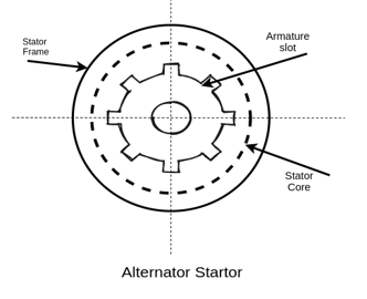
Fig 1 Construction
Rotor construction:
a) Salient pole rotor:
A salient pole rotor consists of poles projecting out from the source of the rotor core.
Salient pole rotors are normally used for routers with four or more poles.
Damper bars are usually inserted in the pole faces to damp out the rotor oscillations during a sudden change in load conditions.
A salient pole synchronous machine has a non-uniform air gap. The air is minimum under the pole centers, and it is maximum in between the poles.
The pull faces are so shaped that the radial autograph length increases from the pole center to the pool ties so that the flux distribution in the air gap is sinusoidal.
The individual field pole windings are connected in series to give an alternative North, and South polarities.
The ends of the field windings are connected to a DC source through the brushes on the slip rings
Salient pole generators have a large number of poles and operate at low speed. A salient pole generator has a comparatively large diameter and a short axial length. The larger diameters accommodate a large number of poles.
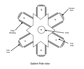
Fig 2 Salient Pole Rotor
b) Cylindrical rotor: -A cylindrical rotor machine is called a non-salient pole rotor machine. It has its rotor so constructed that it forms a smooth cylinder.
Cylindrical rotors are made from solid forgings of high-grade nickel-Chrome-molybdenum steel.
In about two-thirds of the rotor periphery, slots are cut at regular intervals and parallel to the shaft. Field windings are accommodated in these slots. The winding is of distributed type.
The unslotted portion of the rotor from two or four poles.
A cylindrical rotor machine has a comparatively small diameter and long axial length. Such construction limits the centrifugal forces. Thus, cylindrical rotors are particularly useful in high-speed machines.
The cylindrical rotor types alternator has two or four poles on the rotor. Such a construction provides greater mechanical strength and permits more accurate dynamic balancing.
The smooth rotor of the machine makes fewer wind losses, and the operation is less noisy because of the uniform air gap.
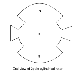
Fig 3 End View of cylindrical rotor
AC generators are usually called an alternator. They are also called synchronous generators. Rotating machines that rotate at a speed fixed by the supply frequency and the number of poles are called synchronous machines.
Most alternators have the rotating field and the stationary armature. The rotating field type alternator has several advantages over the rotating are major type alternators.
- A stationary armature is more easily insulated for the high voltage for which the alternator designs. The generated voltage may be as high as 33kv.
- The armature windings can be braced better mechanically against high electromagnetic forces due to large short-circuit currents when the armature windings are in the stator.
- The armature windings coma being stationary, are not subject to vibration, and centrifugal forces.
- The output current can be taken directly from fixed terminates on the stationary armature without using slip Transcona brushes etc.
- The rotating field is supplied with direct current usually the field voltage is between 100 to 500 balls. Only two rings are required to provide direct current 3 slip rings that would be required for a rotating armature. The insulation of the to relatively low voltage slip rings from the shaft can be provided easily.
- The bulk and weight of the armature windings are substantially greater than the windings of the field poles. The size of the machine is therefore reduced.
- The rotating field is comparatively light and can be constructed for high-speed rotation.
- The stationary armature may be cooled more easily because I am a teacher who can be made large to provide a number of cooling ducts.
Key takeaway
- A salient pole rotor consists of poles projecting out from the source of the rotor core.
- Salient pole rotors are normally used for routers with four or more poles.
- A cylindrical rotor machine is called a non-salient pole rotor machine. It has its rotor so constructed that it forms a smooth cylinder.
- Cylindrical rotors are made from solid forgings of high-grade nickel-Chrome-molybdenum steel.
Comparison of salient-pole and non-salient-pole type
S. No | Salient Pole Type | Smooth cylindrical Type |
1 | Poles are projecting out from the surface | Unslotted portion of the cylinder acts as poles hence poles are non-projecting |
2. | Air gap is non-uniform | Air gap is uniform due to smooth cylindrical periphery. |
3. | Diameter is high and axial length is small. | Small diameter and large axial length is the feature. |
4. | Mechanically weak. | Mechanically robust. |
5. | Preferred for low speed alternators. | Preferred for high speed alternators i.e., for turbo alternators. |
6. | Prime mover used are water turbines I.C engines. | Prime movers used are steam turbines, electric motors. |
7. | For same size, the rating is smaller than cylindrical type. | For same size, the rating is higher than salient pole type. |
8. | Separate damper winding is provided. | Separate damper winding is not necessary. |
Rotating-field type and Rotating-armature type
According to the arrangement of the field and armature windings, synchronous machines may be classified as rotating-armature type or rotating-field type.
1. Rotating-Armature Type:
The armature winding is on the rotor and the field system is on the stator. The generated current is brought out to the load via three (or four) slip-rings. Insulation problems, and the difficulty involved in transmitting large currents via the brushes, limit the maximum power output and the generated electromagnetic field (emf). This type is only used in small units, and its main application is as the main exciter in large alternators with brushless excitation systems.
2. Rotating-Field Type:
The armature winding is on the stator and the field system is on the rotor. Field current is supplied from the exciter via two slip-rings, while the armature current is directly supplied to the load. This type is employed universally since very high power can be delivered. Unless otherwise stated, the subsequent discussion refers specifically to rotating-field type synchronous machines.
Excitation systems for synchronous machines:
Excitation means the production of flux by passing current in the field winding direct current is required to excite the field winding on the rotor of the synchronous machines.
For small machines, DC is supplied to the rotor field by a DC generator called exciter. For medium-sized machines, AC excited I used in place of DC excited. The output of an AC exciter is rectified, and supplied through brushes, and slip ring to the rotor windings of the main synchronous machines. For large synchronous generators at present uses brushless excitation systems.
Speed, and frequency:
The frequency of the generated voltage depends upon the number of field poles, and on the speed at which the field poles are rotated.
One complete cycle of voltage is generated in an armature coil when a pair of field poles (one north, and one south pole) passes over the coil.
Let P=total number of field poles
p=pair of field poles
N=speed of the field poles in r.p.m
n=speed of the field poles in r.p.s
F=frequency of the generated voltage in Hz.
 &
& 
In one revolution of the rotor coma, and the armature coil is cut by  north poles, and
  south poles.
Since one cycle is generated in an armature coil when a pair of field poles passes over Qualcomm are the number of cycles generated in one revolution of the rotor will be equal to the number of pairs of the pole.
Number of cycles per revolution=p
Also, the common number of revolutions per second = n
Frequency =number of cycles per second
=
F=p×n


The speed given by the equation is called synchronous speed.
1.2.1 Principle of operation
The rotor of the alternator is run at its proper speed by its prime mover. A prime mover is a machine that supplies the mechanical energy input to the alternator. Hydraulic turbines commerce steam and gas turbines are used as prime movers. As the poles of the rotor move under the armature conductor on the status of the file, and flux cut the armature conductors. Therefore, voltage generates in these conductors. This voltage of alternating nature of our sins poles of alternative polarity successively passes by a given stator conductor.
1.2.2 EMF equation and Winding Factor
Let  =useful flux per pole in weber
P=total number of poles.
 =total number of conductors or equal sides in series per phase.
 =total number of coils or turns per phase.
n=speed of rotation of rotator is revaluation per second.
F=frequency of generated voltage.
Since the flux per Pole is  , each stator conductor cuts a flux
  .
.
The average value of generated voltage per conductor
=(
Since n revolutions are made in one second, one revolution will be made in 1/n second. Therefore, the time for one revolution of the armature is 1/n second. The average voltage generated per conductor is


Since there are  conductors in series per phase, the average voltage generated per phase are given by

Since.

For the voltage wave, the form factor is given by

For sinusoidal voltage KF=1.11


Above equation has been derived with the following assumptions
a) Coils have got a full pitch
b) All the conductors are concentrated in one stator slot.
Winding Factors
Winding Factor: The combined effect of coil span factor and distribution factor is known as winding factor. In fact, winding factor is the product of coil span factor and distribution factor.
1.2.3 Rating of generator
The voltage per phase, current per phase and number of phases defines the rating of generator. It is expressed in MVA or kVA. It can also be defined as the operating voltage between two of its three terminals. For delta connection it equals the phase winding voltage. For star connection it is equal to √3 times the phase-winding voltage.
1.2.4 Generator on no-load and on balanced load
The factors on which the behavior of synchronous generator depends are on the power factor of load and on the connection. The type of connection means whether it is operating in parallel or alone. Practically, synchronous generators always operate as part of large power systems. Let us consider that the synchronous generator is working alone. According to our assumptions the generator operates at constant speed.

Fig 4 Generator operating alone
The reactive power from generator increases with increase in load. The field current, flux and the field resistor are all constant. Therefore, the speed is also constant keeping the magnitude of internal generated voltage as constant. Assuming the same power factor of the load, change in load will change the magnitude of the armature current IA. However, the angle will be the same (for a constant PF). Thus, the armature reaction voltage jXSIA will be larger for the increased load. Since the magnitude of the internal generated voltage is constant
EA=Vɸ+jXsIA
The basic demand is to generate a constant terminal voltage by generator. By controlling the internal voltage, the terminal voltage is controlled.
EA = K.
This may be done by changing flux in the machine while varying the value of the field resistance RF, which is summarized:
1. Decreasing the field resistance increases the field current in the generator.
2. An increase in the field current increases the flux in the machine.
3. An increased flux leads to the increase in the internal generated voltage.
4. An increase in the internal generated voltage increases the terminal voltage of the generator.
Key takeaway
- For lagging (inductive) loads, the phase (and terminal) voltage decrease.
- For unity power factor (purely resistive) loads, the phase (and terminal) voltage decrease.
- For leading (capacitive) loads, the phase (and terminal) voltage rise.
1.2.5 Voltage drop due to armature resistance, leakage flux and synchronous reactance. Armature reaction and its effect under different load power factors
Armature windings
The winding through which a current is passed to produce the main flux is called the field winding.
The winding in which voltage is induced is called the armature winding some basic terms related to the armature winding are defined as eternal consists of two conductors connected to one end by an end connector. A coil is formed by connecting several turns in series.
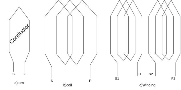 A winding is formed by connecting several coils in series.
Fig 5 Winding formed by several coils in series
 =Mechanical degrees or angular measure in space
 = Electrical degree of angular measure in cycles
For p pole machine, the electrical degree is defined as

The angular distance between the centers of two adjacent pole on a machine is known as pole pitch or pole span.
One pole pitch=180° elect degree =
Regardless of the number of poles in the machine, a pole pitch is always 180° electrical degrees.
The two sides of a coil are placed in two slots on the stator surface. The distance between the two sides of a coil is called the coil pitch. If the coil pitch is one pole pitch coma it is called the full pitch coil. If the coil pitch is less than one pole pitch of the coil is called the short pitch coil for fractional pitch coil.
Coil span factor or pitch factor-
The distance between the two sides of a coil is called the coil span or coil pitch.
The angular distance between the central line of one pole to the central line of the next Pole is called pole pitch. A pole pitch is always 180 electrical degrees regardless of the number of poles on the machine.
A coil having a span equal to 180° electrical is called a full pitch coil.
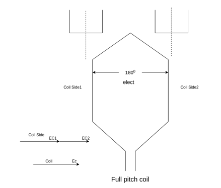
Fig 6 Full Pitch Coil
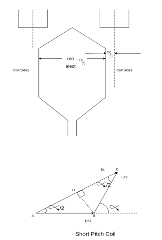
Fig 7 Short Pitch Coil
A coil having a span less than 180° electrical is called a short pitch coil, for fractional pitch coil. It is also called a chorded coil. A stator winding using fractional pitch coils is called a chorded winding. If the span of the coil is reduced by an angle  electrical degrees, the coil span will be (
 ) Electrical degrees.
The coil span factor or pitch factor  is defined as the ratio of the voltage generated in the short pitch coil to the voltage generated in the full pitch coil. The coil span factor is also called the chording factor.


For full pitch coil,  , and
, and
 For short pitch coil
Advantages of short pitching or chording
1) Shortens the end of the winding, and therefore there is shaving in the conductor material.
2) Reduces the effects of distorting harmonics, and thus the waveform of the generated voltage is improved and making it approach A sine wave.
Distribution factor or breadth factor 
In a concentrated winding, the coil side of a given face is concentrated in a single slot under a given Pole. The individual coil voltage is induced and is in phase with each other. These voltages may be added arithmetically.
In actual practice, in each phase comic walls are not concentrated in a single slot but are distributed in a number of slots in space to form a polar group under each pole.
The voltages induced in a coil side constituting a polar group are not in the face but differ by an angle equal to the angular displacement of the slots.
The distribution factor or bread factor is defined as the ratio of the actual voltage obtained to the possible voltage if all the coils of a polar group were concentrated in a single slot.

Let m=slots per pole per phase

 = Angular displacement between adjacent slots in electrical degrees


It is to be noted that the distribution factor  for a given number of phases is dependent only on the number of distributed slots under a given pole. It is independent of the type of winding, lap or wave, or the number of turns per coil, etc.
As the number of slots per pole increases the distribution factor decreases.
Actual voltage generated
Taking the coil span factor, and distribution factor into account the actual generated voltage per phase is given by

Is called the complete EMF equation of an alternator
The quantity ( is sometimes called effective turns per phase

It is smaller than the actual number of turns per face due to fractional pitch coils, and due to the distribution of winding over several slots under each pole.
The coil span factor and distribution of a winding are sometimes combined into a single winding factor  which is the product of

For Star connected alternator the line voltage is √3 times the phase voltage.

The angle between the terminal voltage v and the internal voltage is the machine angle or rotor angle
Numerical
Example 1. A 3-phase, 50Hz, 8 pole alternator has a star connected winding with 120 slots, and 8 conductors per slot. The flux per Pole is 0.05 WB. Sinusoidally distributed. Determine the phase and line voltages.
The full pitch coil


=0.9567
Total number of conductors=conductor per slot × number of slots
Z=8×120=960
Conductors per phase 

Generated voltage per phase


Generated voltage line


Example 2. A 3 phase 6 pole star connected alternator revolves at 1000 r.p.m. The stator has 90 slots and 8 conductors per slot. The flux per Pole is 0.05 wb (Sinusoidally distributed). Calculate the voltage generated by the machine if the winding factor is 0.96.

Total number of stator conductors=conductors per slots × number of slots
=8×90=720
Stator conductors per phase


Generated voltage per phase


Generated line voltage=


Example 3. A 3 phase, 16 Pole synchronous generator has a resultant air-gap flux of 0.06 wb per pole. The flux is distributed sinusoidally over the pole. The stator has two slots per pole per phase, and 4 conductors per slot are accommodated in two layers. The coil span is 150° electrical. Calculate the phase, and line induced voltage when the machine runs at 375 r.p.m.
m=Slots per pole per phase=2
Total slots=2×16×3=96
Total number of conductors=slots × conductors per slot
=96×4
=384
Number of conductors per phase


The angular displacement between adjacent slots


=0.9659
Since the flux is sinusoidally distributed

The generated voltage per phase is given by


Example 4. A 3 phase, 50 hertz, 2 pole star connected turbo alternator has 54 slots with 4 conductors per slot the pitch of the coils is two slots less than the pole pitch. If the machine gives 3300V between lines on the open circuit with sinusoidal flux distribution, determine the useful flux per pole.


Coil pitch=25 slot angles


=0.95547
Total number of conductors per phase=

=72


Example 5. A 4 pole, 3 phase, 50-hertz star connected alternator has 60 slots with two conductors per slot and having armature winding of two-layer type quasar short-pitched in such a way that if one coil sides lie in slot number one of the other lies in slot number 13. Determine the useful flux purple required to generate line voltage of 6000 volt.


Coil Span=12


Armature leakage reactance:
In an AC machine, any flux set up by the load current which does not contribute to the useful flux of the machine is a leakage flux.
The effect of this leakage flux is to set up a self-induced emf in the armature winding the leakage flux is may be classified as
- Slot leakage
- Tooth head leakage
- Coil end for overhang leakage.
The voltage induced in the armature windings by the air gap flux is called air gap voltages.
The leakage flux also induces a voltage in the armature winding these are taken into account by introduction of leakage reactance drops. Most of the reluctances of the magnetic circuits for armature leakage fluxes are due to air paths. The fluxes are, therefore nearly proportional to the armature current producing them and are in phase with these currents. The voltage induced in the armature windings can be considered with the leakage reactance drops, and lead the current producing them by 90.
Armature reaction in synchronous machines:
When current flows through the armature winding of an alternator the resultant MMF produces flux. The armature flux reacts with main Pole flux causing the resultant flux to become either less than or more than the original main field flux. (The effect of armature (stator) flux on the flux produced by the rotor field poles is called armature reaction).
For simplicity, we considered a 3 phase 2 pole alternator having a single layer winding but this treatment is valid for any number of poles. Also, the winding of each phase is assumed to be concentrated but the effect of armature reaction will be the same as if a distributed winding were used.
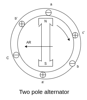
Fig 8 Two pole alternator
The power factor will be defined as the cosine of the angle between the armature phase current, and the induced EMF in the armature conductor in that phase.
a) Armature reaction at unity power factor:
Suppose that the alternator is supplying current at unity power factor the phase currents  ,
,  , and
, and  will be in phase with their respective generated voltage
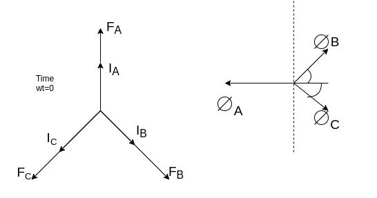
Fig 9 Phasor for UPF
The projections of phasor on the vertical Axis give its instantaneous value. At t=0, the instantaneous values of the currents and fluxes are given by.


Where the subscript m denotes the maximum value of current, and flux.
Since the fluxes  , and
, and  are negative. They are acting opposite to the direction shown above. They are shown by OB, and OC. The resultant of the fluxes can be found by resolving the fluxes horizontally and vertically
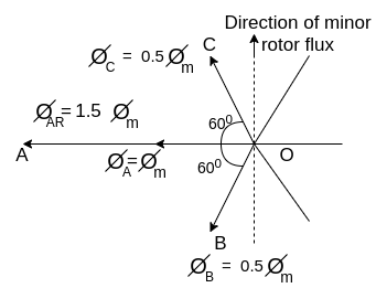
Fig 10 Direction of minor rotor flux
Resolving along the horizontal direction we get


Resolving along the vertical direction we get


=0
The resultant armature reaction flux is given by


The direction of this resultant flux is along OA, and the resultant armature reaction flux  is constant in magnitude equal to 1.5
 .
.
Also  lags behind 90 with the main field flux. This is called the cross-magnetizing flux.
b. Armature reaction: -Lagging power factor
Suppose that the alternator is loaded with an inductive load of zero power factor lagging. The phase current  will be lacking with their respective phase voltage
  by 90°.
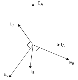
Fig 11 Phasor for Lagging power factor
At time t=0 the instantaneous values of currents and fluxes are given by
 ,
, 


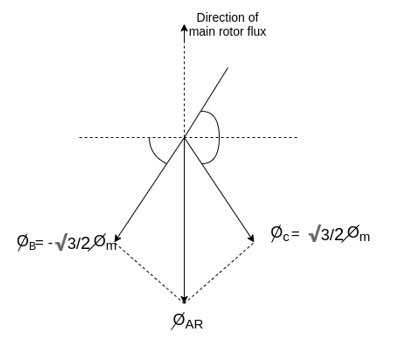
Fig 12 Direction of main rotor flux
The resultant flux is


It is seen that the direction of the armature reaction flux is opposite to the main field flux. Therefore, it will oppose, and weaken the main field flux. It is said to be demagnetizing.
c. Armature reaction: Leading power factor
Suppose that the alternator is loaded with a load of zero power factor leading. The phase  will be leading their respective phase voltages
  by 90°
At time t=0 the instantaneous values of currents and fluxes are given by
 ,
, 


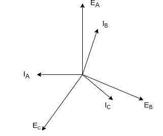

Fig 13 Phasor for Leading power factor
The resultant flux is given by


It is seen that the direction of the armature reaction flux is in the direction of the main field flux. Does it will aid it. In other words, it is a magnetizing flux.
Synchronous Impedance:
The actual generated voltage consists of the summation of two-component voltages. One of these component voltages is the voltage that would be generated if there were no armature reaction. It is the voltage that would be generated because of only the field excitation. This component of the generated voltage is called the excitation voltage  .
.
The other component of the generated voltage is called the armature reaction voltage .
.

 is the equivalent to a voltage of inductive reactance, and

In addition to the effects of armature reaction, the stator winding also has a self-inductance and a resistance.
Let  = self-inductance of the stator winding
 = self inductive reactance of stator winding
 =armature resistance
The terminal voltage V is given by

Where  =armature resistance drops
 =armature leakage reactance drops
 =armature reaction voltage
Synchronous reactance can be represented as


The impedance  is called the synchronous impedance.
Key takeaway
In an AC machine, any flux set up by the load current which does not contribute to the useful flux of the machine is a leakage flux.
The effect of this leakage flux is to set up a self-induced emf in the armature winding the leakage flux is may be classified as
- Slot leakage
- Tooth head leakage
- Coil end for overhang leakage.
1.2.6 Per phase Equivalent Circuit and Phasor Diagram
Equivalent circuit, and phasor diagram of a synchronous generator
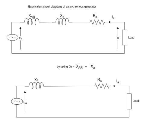
Fig 14 Equivalent Circuit Diagram of Synchronous Generator
a) Unity power factor


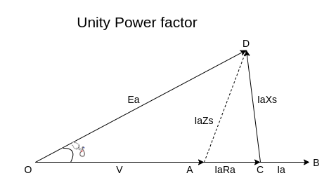
Fig 15 Phasor for UPF
b) Lagging power factor


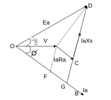
Fig 16 Phasor for Lagging PF
c) Leading power factor
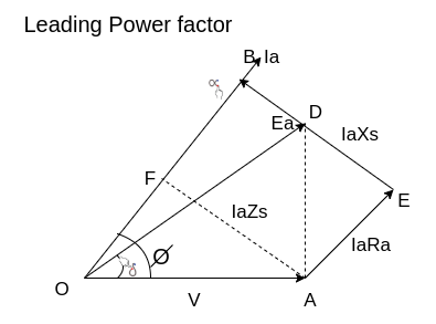
Fig 17 Phasor for leading power factor


Key takeaway
UPF

Lagging Power Factor

Leading Power Factor

1.2.7 Power-Power Angle Relation
The graphical representation of electrical output and the power angle is called as power angle curve. The Load angle is another name given to power angle. The relation between electrical power and load angle is given as
Pe= EfVtXs/Sin 
Ef= no load excitation voltage
Vt= generator terminal voltage
Xs= generator synchronous reactance and
δ= load angle respectively.
Now, the graph between Pe i.e., power and power angle δ is shown below.
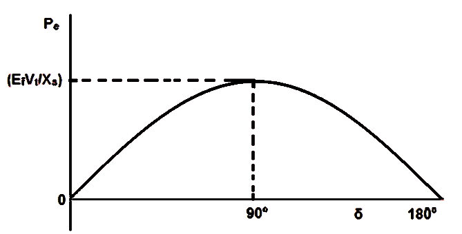
Fig 18 Power w.r.t δ is called Power Angle Curve
The power angle curve is very important as it helps in study of stability of synchronous machine. The generator electrical output is less than the mechanical input. Therefore, the poles of the machine will start to slip and eventually it will lose synchronism. Thus, the machine i.e., generator becomes unstable. Steady state stability limit is the maximum power flows possible through a specific point without loose of synchronism, when the power is increased gradually. Therefore, steady state stability limit of synchronous machine corresponds to power for load angle δ = 90°. To be accurate, it will be (EfVt/Xs).
Transient state stability limit is basically the maximum amount of power flow possible without loss of synchronism when a sudden disturbance occurs. The transient stability limit is determined by Equal Area Criteria which uses power angle curve.
1.3.1 Armature reaction as per Blondel’s two reaction theory for salient-pole machines
Two reaction theory
Two reaction theory was proposed by, Andre Blondel. The theory proposes to resolve the given armature mmfs into two mutually perpendicular components, with one located along the axis of the rotor salient pole. It is known as the Direct axis component. The other component is located perpendicular to the axis of the rotor salient pole. It is known as the quadrature axis component. The d axis component of the armature MMF  is denoted by
  , and the q axis component by
  The component
  is either magnetizing or demagnetizing. The component
  results in a cross-magnetizing effect.
If  is the angle between the armature current
  , and the excitation voltage
  is the amplitude of the armature MMF, then

And 
The magnetic axes of the rotor
The axis of symmetry of the north magnetic poles of the rotor is called the Direct Access or d-axis.
The axis symmetry of the South magnetic poles is called the negative d-axis.
The axis of symmetry half way between adjacent North and South poles is called quadrature axis or q-axis. The q axis legging the north pole is taken as the positive q axis.
The quadrature access is so named because it is  electrical degrees (one-quarter cycle) away from the direct axis.
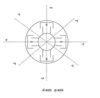
Fig 19 d-axis, q-axis [Direct axis, quadrature axis]
1.3.2 Direct-axis and quadrature-axis synchronous reactance’s and their determination by slip test. Phasor diagram of salient-pole generator and calculation of voltage regulation.
Salient pole synchronous machine two reaction model
In the cylindrical rotor synchronous machine, the air gap is uniform. The protruding pole structure of the rotor of a salient pole machine makes the air gap highly non-uniform. Consider a two-pole rotor rotating in the anticlockwise direction within a two-pole stator.
The Axis along the axis of the rotor is called the d axis, and the axis perpendicular to the d axis is called the quadrature axis.
It is seen that the direct Axis flux path involves too small air gaps, and is the path of minimum reluctance. The path denoted by has too large air gaps, and is the path of maximum reluctance.

Fig 20 Salient pole synchronous machine two reaction model
The rotor flux  is shown vertically upwards, this rotor flux induces a voltage
  in the stator.
If a lagging p.f. The load is connected to the synchronous generator, a stator current  will flow, and it lags behind the generated voltage
  by an angle
  .
.
The armature current produces stator mmf  which will lags behind
  by 90°. The stator MMF
  produces a magnetic field
  along its direction, and it can be resolved into two components the Direct axis component
  , and the quadrature axis component
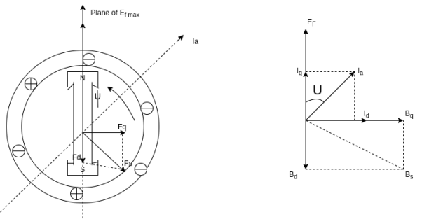 Fig 21 Phasor for d-axis and q-axis
If 
Where  =reluctance of direct Axis flux path
 =reluctance of q axis flux path
Since  the Direct axis component of mmf
  produces more flux than the quadrature axis component mmf
The direct, and quadrature axis stator flux is produced voltages in the stator winding by armature reaction.
Let  =direct Axis component of armature reaction voltage
 =quadrature Axis component of armature reaction voltage.
We can write


Where  =armature reaction reactance in the Direct axis per phase.
 = armature reaction reactance in the quadrature axis per phase.
The value of  is always less than
  since the EMF induced by a given mmf acting on Direct access is smaller than for the quadrature axis due to its higher reluctance.


Considering the resistance, and leakage reactance of the armature,

If  = the q-axis component of
  in phase with
 .
.
 =the d- axis component of
  lagging
  by 90°


Let


The reactance  is called the direct Axis synchronous reactance, and the reactance
  is called the quadrature axis synchronous reactance.

The above equation is the final form of the voltage equation for a salient pole synchronous generator.
Phasor diagram
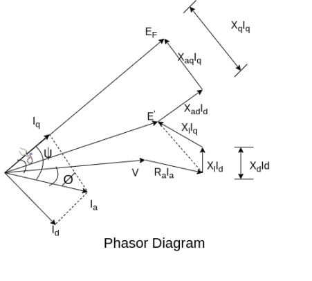
Fig 22 Phasor for salient pole synchronous generator.
Simplified phasor diagram
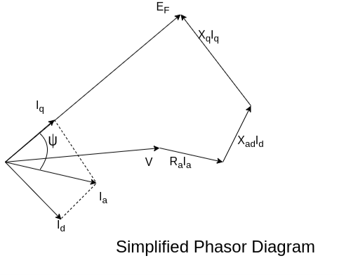
Fig 23 Simplified Phasor Diagram

Since 


 is taken positive for lagging power factor, and it will be taken negative for the leading power factor.
If the armature resistance is neglected

Determination of 
The direct, and quadrature axis synchronous reactance of a salient pole synchronous machine can be determined form a simple no-load test known as slip test.
In this test, a small voltage at rated frequency and not more than about 25 % of the rated value is applied to the 3 phase stator winding. The field winding is excited and left open-circuited.
The rotor is driven by an auxiliary motor at high speed slightly less or slightly more than synchronous speed. The direction of rotation should be the same as that of the rotating field produced by the stator. A small voltage reading indicated by the voltmeter across the open field winding terminal shows that the direction of rotation of the rotor is proper. Since the rotor is running at a speed  close to synchronous speed
  there will be a small slip between the rotating magnetic field produced by the armature, and the actual salient field poles.
Since the stator mmf moves slowly past the actual field poles, there will be an instant when the peak of the armature mmf wave is in line with the axis of the actual salient field poles.

Fig 24 Determination of Xd and Xq
Construction:
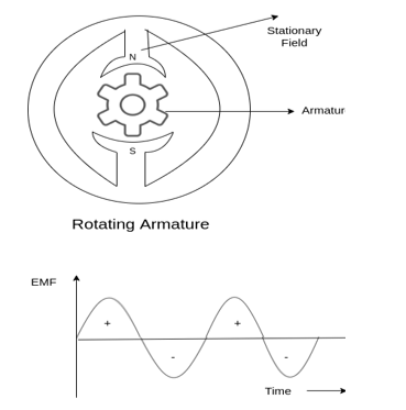
Fig 25 Construction
Rotating field type (stationary armature):
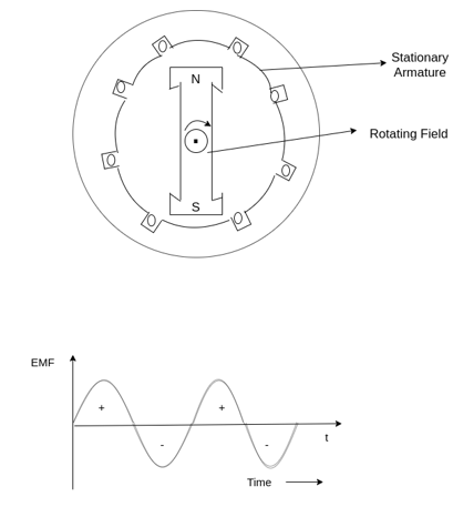
Fig 26 Rotating field type
Sr. No. | Salient pole type synchronous machine | Non-salient pole type synchronous machine |
1 | Diagram 
| Diagram 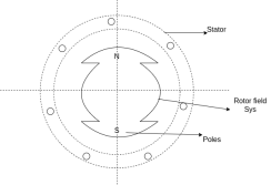 |
2 | Projected out poles | Merged in polls |
3 | Rotor surface is projected | Smooth rotor surface |
4 | The diameter of the machine is large | The small diameter of the machine |
5 | The axial length of the machine is small | The axial length of the machine is large |
6 | Speed is slow | Speed is high |
7 | Air gap is non uniform | Air gap is uniform |
8 | Damper bars/winding is used | Damper bar/winding not used |
9 | The air gap between stator and rotor is non-uniform | The air is uniform between stator and rotor |
10 | Centrifugal stress is more | Centrifugal stress is less |
11 | Aerodynamic resistance is more | Aerodynamic resistance is less |
Problem
A 3 phase 16 pole alternator has a star connected winding with 144 slots, and 10 conductors per slot. The flux per pole=0.03 Wb sinusoidally distributed, and speed is 375 rpm.
Find
1) Frequency
2) Phase voltage
3) Line voltage
Solution

Total conductors= 144×10=1440


For  as coil pitch is not mentioned take full pitched coil.
 =1
=1


For star connection,

Problem
A 3 phase 4 pole alternator has 60 slots, two conductors per slot. The pitch of the coils is 3 slots less than full pitch. Find 
Pole pitch=
Now 15 slots=180


Armature reaction
The effect of armature flux  on the flux produced by the field poles or the main flux
  is called armature reaction.
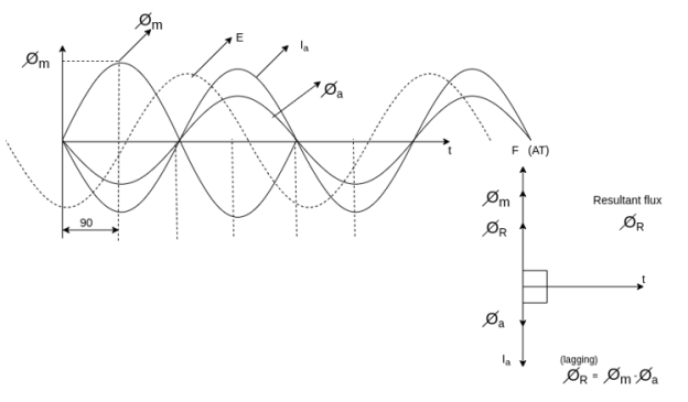
This effect is different for different nature of p.f. Of the load.
1) The effect may be cross magnetizing i.e.,
2) It may be strong magnetizing or magnetizing i.e., is in the same direction as
  , So both are added, and the resultant field becomes stronger.
3) It may be demagnetizing i.e.,  , and hence
  weakens.
Different nature of p.f.
1) Unity PF
2) Zero PF lagging
3) Zero PF leading
Unity PF-: in this case  is in phase with E.
Phasors relations:
1) E lag 
2)  in phase with E
3) Field ampere-turns i.e., F and 
4) Flux produced by  in phase with
  that is
The armature flux  crosses the main flux
  from the winding field, and vector diagram or Phasors.
Also, the armature flux crosses the resultant flux so for the unit PF the armature reaction is such that the main flux  is crossed or distorted. It is a cross magnetizing effect.

Zero lagging PF
It is seen that for lagging PF the armature flux is in direct opposition to flux  Hence it is demagnetizing, and resultant flux
Hence in the case of lagging PF, the effect of armature reaction is demagnetizing.
References:
[1] Nagrath and Kothari, Electrical Machines, 2nd Ed., Tata McGraw Hill.
[2] S. K. Bhattacharya, Electrical Machines, Tata McGraw Hill.
[3] A.S. Langsdorf, Theory of Alternating Current Machinery, Tata McGraw Hill
[4] P. S. Bimbhra, Electric Machinery, Khanna Publications.
[5] B.R. Gupta and Vandana Singhal -Fundamentals of Electric Machines, New Age International (P) Ltd.
[6] B. L Theraja –Electrical Technology, Vol II , S. Chand publication.