Unit - 4
3 phase induction motor, induction generator and special purpose motors
The rotor speed of an induction motor is given by

And


From the above equation, it is seen that the motor speed can be changed by a change in frequency f, number of poles P and slips.
The torque produced by a three-phase induction motor is given by

When the rotor is at standstill slip S is 1, so the equation of torque is

Where,
 is the rotor EMF
 is the synchronous speed
 is the rotor resistance
 is the rotor inductive reactance
The speed of induction motor is changed from both stator and the rotor side.
The speed control of induction motor from the stator side are further classified as,
1) Changing the number of stator poles.
2) Controlling supply voltage
3) V/f control or frequency control
4) Adding rheostat in the stator circuit
The speed control of 3 phase induction motor from the rotor side are further classified as
1) Adding external resistance on the rotor side
2) Cascade control method
3) Injecting slip frequency EMF into the rotor side.
a) Stator side speed control methods
- Pole changing methods:
The number of stator poles can be changed by
a) Multiple stator windings- In this method, the stator is provided with two separate windings which are wound for two different pole numbers.
b) Method of consequent poles: In this method a single static winding is divided into two coils groups. The terminals of all these groups are brought out. The number of poles can be changed with only simple changes in coil connections. The number of poles can be changed in the ratio of 2:1.
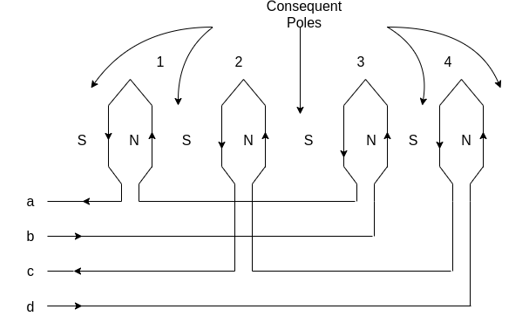
Fig 1 Method of consequent poles
c) Pole amplitude modulation technique: This method of speed control by pole changing are suitable for cage motors only because the cage the rotor automatically develops a number of poles equal to the poles of the stator winding.
2. Controlling supply voltage:
The speed of a three-phase induction motor can be varied by varying the supply voltage.

Where 

Therefore, the speed of the rotor at maximum torque is

The torque developed is proportional to the square of the supply voltage and the slip at maximum torque is independent of the supply voltage.
Variation of supply voltage does not alter the synchronous speed also.
Torque speed characteristics of a three-phase induction motor for varying supply voltage and a fan load is shown below.
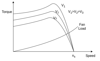
Fig 2 Torque speed characteristics of a three-phase induction motor
Speed control is obtained by varying the supply voltage until the torque required by the load is developed at the desired speed.
As the torque is proportional to the square of the supply voltage and current is proportional to the voltage. Therefore, as a voltage is reduced to reduce speed for the same current the torque developed by the motor is reduced.
This method is suitable for applications where load torque decreases with speed, as in the case of a fan load.
The speed of the motor can be varied within a small range by this method.
Since the operation at voltage is higher than the rated voltage is not permissible, this method allows speed control only below the normal rated speed.
This method is suitable for fan or pump drives where the load torque varies as the square of the speed. These drives require low torque at low speeds and this can be obtained with low applied voltage without excessive motor current.
3. V/F control or variable frequency control
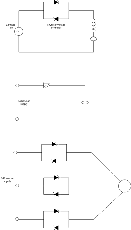
Fig 3 Variable frequency control method
The synchronous speed of an induction motor is given by 
The synchronous speed and therefore the speed of the motor can be controlled by varying the supply frequency.
The EMF induced in the stator of the induction motor is given by

Therefore, if the supply frequency is changed,  will also be changed to maintain the same air gap flux. If the stator voltage drop is neglected the terminal voltage
  is equal to
  To avoid saturation and to minimize losses, the motor is operated at rated air gap flux by varying terminal voltage with frequency to maintain ratio constant at the rated value. This type of control is known as constant voltage per hertz.
The variable-frequency supply is generally obtained by the following converters
1) Voltage source inverter
2) Current source inverter
3) Cycloconverter
Inverter converts of fixed voltage DC to a fixed voltage AC with variable frequency.
A cycloconverter converts a fixed voltage and fixed frequency AC to a variable voltage and variable frequency AC.
Cycloconverter controlled induction motor drive is suitable only for large power drives and to get low speeds.
4. Adding rheostat in the stator circuit
In this case, the rheostat is added in the stator circuit due to this, voltage gets dropped. In case of three phase induction motor torque produced is given by  .
.
If we decrease supply voltage torque will also decrease. But for supplying the same load, the torque must remain the same and it is only possible if we increase the slip and if the slip increases motor will run at reduce speed.
b) The rotor side speed control methods
1) The rotor resistance control
The speed of the wound induction motor can be controlled by connecting external resistance in the rotor circuit through slip rings. This method is not applicable cage motors.

If  = value of slip corresponding to maximum torque then
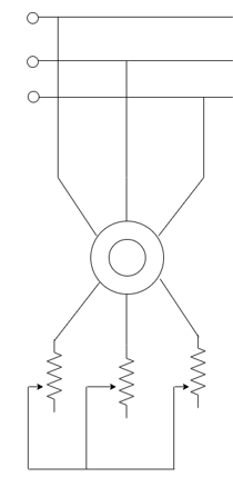
Fig 4 Rotor resistance control


And

The maximum torque is independent of the rotor circuit resistance, maximum torque varies inversely as a standstill reactance of the rotor. The slip at which the maximum torque depends upon the rotor resistance in the rotor circuit, maximum torque can be obtained at any desired slip or motor speed.
Therefore, by this method, control is provided from the rated speed to lower speed.
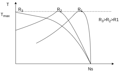
Fig 5 Torque Speed Characteristics
1) Low slip

2) Medium slip

3) High slip  decreases beyond the
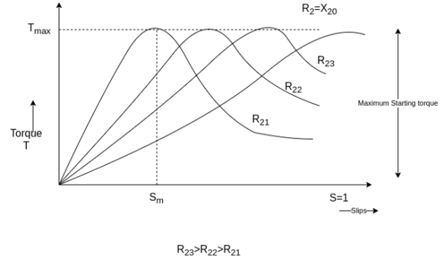
This method is very simple. It is possible to have a large starting torque, low starting current and large pull-out torque at small values of slip.
The major disadvantage of the rotor resistance control method is that the efficiency is low due to additional losses in resistors connected in the rotor circuit.
This method is used in crane, Ward-Leonard drives applications.
2. Slip energy recovery
In the rotor resistance control, the slip power in the rotor circuit is wasted as  loss during the low-speed operation. The efficiency of the drive system by this method of speed control is therefore reduced.
The slip power from the rotor circuit can be recovered and fed back to the AC source to utilize it outside the motor. Thus, the overall efficiency of the drive system can be increased.
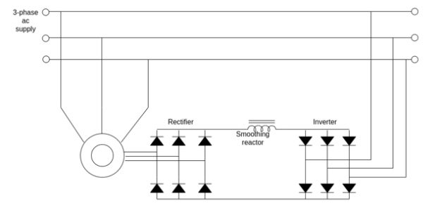
Fig 6 Slip energy recovery
By neglecting the stator and the rotor drops the voltage  is given as

Where S=per unit slip,  =stator line voltage,
 = stator to rotor turn ratio of the machine

Where  =transformer line side to inverter AC side turn ratio and
  =inverter firing angle. Range is
Since  and
and  mast be balance,

Therefore, the speed is given by


The above equation shows that the torque is proportional to the current  , with higher load torque
  the machine tends to slow down and current
  increases so that
  .
.
The main advantage of this type of speed control of 3 phase induction motor is that a wide range of speed control is possible whether it's above normal or below normal speed.
Key takeaway
The variable-frequency supply is generally obtained by the following converters
1) Voltage source inverter
2) Current source inverter
3) Cycloconverter
The speed control of induction motor from the stator side are further classified as,
- Changing the number of stator poles.
- Controlling supply voltage
- V/f control or frequency control
- Adding rheostat in the stator circuit
The speed control of 3 phase induction motor from the rotor side are further classified as
- Adding external resistance on the rotor side
- Cascade control method
- Injecting slip frequency EMF into the rotor side.
An induction machine is sometimes used as a generator.
The following figure shows the complete torque-speed characteristic of a three-phase induction machine for all ranges of speed.
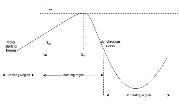 Fig 7 Torque-Speed characteristic of a three-phase induction machine for all ranges of speed.
Initially, the induction machine is started as a motor. It draws lagging reactive volt-ampere from the main supply.
Then the speed of the machine is increased above the synchronous speed by an external prime mover in the same direction as the rotating field produced by the stator windings.
Then the induction machine will operate as an induction generator and will produce generating torque. This generating torque is opposite to the rotation of the rotor. Under these circumstances the slip is negative and the induction generator delivers electrical energy to the supply mains.
The output of the induction generator depends upon the magnitude of the negative slip or on how fast the above synchronous speed the rotor is driven in the same direction.
In generating mode, there is a maximum possible induced torque called push over-torque of the generator. If the prime mover applies a torque greater than the pushover torque, The generator will over speed.
The rotating magnetic field in the polyphase induction motor is produced due to the exciting current supplied to the stator winding from the supply line. The supply must continue to be available even if the machine-driven above synchronous speed. In other words, an induction generator is not self-excited generator.
In induction generators, the reactive power required to establish the air gap magnetic flux is provided by a capacitor Bank connected to the machine in case of a stand-alone system.
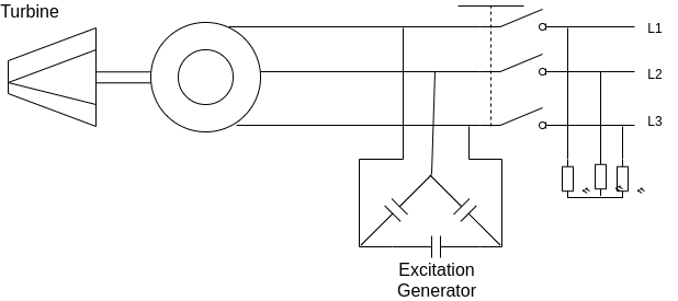 Fig 8 IM as Generator
The motor runs slightly above the synchronous speed at no load by a prime mover.
A small EMF is induced in the stator at a frequency proportional to the rotor speed.
This voltage appears across the three-phase capacitor bank giving rise to a leading current drawn by the capacitor Bank. This is equivalent to the leading current supplied back to the generator.
The flux set up by this current assist current the initial residue flux causing an increase in the net flux, which in turn causes a net increase in voltage. This increase in voltage causes a further increase in exciting current causing a further increase in the terminal voltage.
This voltage builds up to a point where the magnetization characteristic of the machine and the voltage-current characteristic of the capacitor Bank intersects each other.
At this point, the reactive volt-ampere demanded by the generator is equal to the reactive volt-ampere supplied by the capacitor bank.
The operating frequency is affected by the load and it depends upon the rotor speed.
For lagging power factor load the voltage collapses very rapidly.
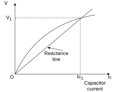
Fig 9 Voltage-Current characteristic of the capacitor Bank
Key takeaway
In generating mode, there is a maximum possible induced torque called push over-torque of the generator. If the prime mover applies a torque greater than the pushover torque, The generator will over speed.
Induction generators are used principally with alternative energy sources such as windmills or wind energy recovery systems for large scale power generation. They are also used to supply additional power to a load in a remote area that is being supplied by a weak transmission line.
Example
A 10 hp, 1760 rpm, 440V, three-phase induction motor operates as an asynchronous generator. The full load current of the motor is 10 A and the full load power factor is 0.8. Determine the required capacitors per phase if capacitors are connected in delta.
Answer-
Apparent power


Active power


Reactive power


For a machine to run as an asynchronous generator, capacitor bank must supply a minimum  VAR per phase
Capacitive current 

Capacitive reactance per phase 
Minimum capacitance per phase


If the load also absorbs reactive power, the capacitor bank must be increased in size to compensate.
Prime mover speed should be used to generate a frequency of 50 Hertz.
Energy-efficient motors:
- An energy-efficient motor produces the same shaft output power but draws less input power compared to the normal motor.
- The electricity consumption is less for the same power output. The energy-efficient motor uses good quality magnetic and insulating materials.
Features of energy-efficient motors:
1) Less electrical energy consumption.
2) Highest operating efficiency.
3) Low running cost.
4) Can work in tough weather conditions.
5) Better overload capacity.
6) Considerable savings in running costs over a period of time.
7) Better cooling.
8) Temperature rise is comparatively less.
9) Insulation life is greater.
These above features exist in the energy-efficient motors because of the following reason:
1) The gap between the stator and the rotor is optimized hence the magnetic losses are reduced.
2) Copper material in the winding is increased.
3) The magnetic material used is of high quality and the stampings used are thinner.
4) The fan and bearing design are optimized.
5) The length of the stator and the rotor is more due to which heat dissipation is effective.
For making the motor energy-efficient following modifications are done:
Stator and the rotor core:
a) instead of low-cost plain carbon steels, silicon Steel with 4% silicon is used. This improves the magnetic properties of the motor.
b) High permeability steel is used this reduces the magnetizing current.
c) Thinner laminations are used, which reduces the Eddy current loss.
d) The rotor die modification is done, if the rotor slots are produced by punching operation, the successive lamination are shorted it is due to contact with Aluminum.
Stator or the rotor winding:
a) these are done to reduce the copper losses for stator the copper conductors are used instead of Aluminum. The copper conductor size is increased to 30 to 40% more.
b) For rotor thicker end rings are used, made up of copper.
Key takeaway
- An energy-efficient motor produces the same shaft output power but draws less input power compared to the normal motor.
- The electricity consumption is less for the same power output. The energy-efficient motor uses good quality magnetic and insulating materials.
Comparison of a standard motor and energy-efficient motor
Parameters | Standard motor | Energy-efficient motor |
Stator and the Rotor material | Low carbon laminated Silicon Steel. | High-grade Silicon Steel. |
Loss in core | More about 6.6 watts/Kg | Low, 3.3 watts/Kg |
Laminations | Thicker lamination increases Eddy current losses | Very thin lamination decreases Eddy current losses. |
Insulation between lamination | Moderate | Insulation improved |
Length of core | Standard length (less) | Longer core length |
Operation noise | More noisy operation | Less noisy operation |
Stray losses | More stray losses | Very less, stray losses |
Air gap | Moderate | Narrow air gap decreases the magnetizing current |
Losses and P.F. | More losses decrease P.F. | Fewer losses better P.F. |
Overload capacity | Lesser capacity | More capacity |
Brushless DC motor
The cross-section of a three-phase 2 pole trapezoidal PMAC motor is shown. It has permanent magnet rotor with wide pole arc. The stator has three concentrated phase windings, which are displaced by 120° and each phase winding span 60° on each side.
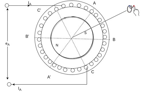
Fig 10 Construction of Brushless DC Motor
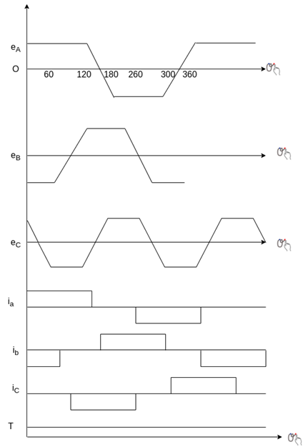
Fig 11 Characteristics of Brushless DC Motor
When a revolving in the counterclockwise direction, up to 120° rotation, all top conductors of phase A will be linking the South Pole, and all bottom conductors of phase A will be linking the north pole.
Hence the voltage induced in phase A will be the same during 120° rotation. Beyond 120° rotation, some conductors in the top link north pole and others the South Pole. The same happens with the bottom conductors.
Hence, the voltage induced in phase linearly reverses in the next 60° rotation. Thus, an inverter fed trapezoidal PMAC motor drive operating in self-controlled made is called DC motor.
A brushless DC motor employing a voltage source converter and a trapezoidal PMAC motor is shown below
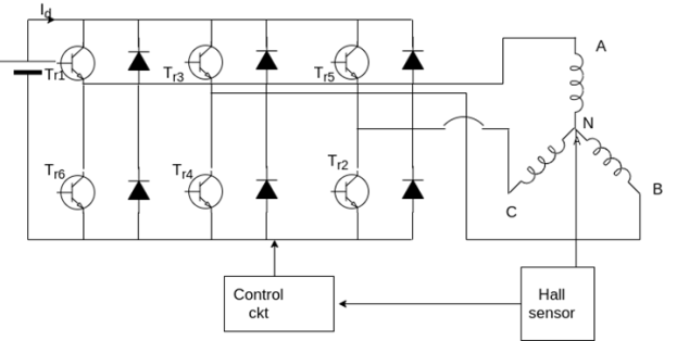


Fig 12 Brushless DC motor employing a voltage source converter and a trapezoidal PMAC motor
During each 60° interval, current enters one phase and comes out of another phase, therefore power supplied to the motor in each such interval is,


Thus, torque is proportional to current  . It can be shown that a DC current
  flows in the DC link.
Regenerative braking operation is obtained by reversing phase currents.
Like a DC motor, inverter fed trapezoidal PMAC motor has a voltage induced proportional to speed, torque is proportional to armature current, and stator and the rotor fields remain stationary with respect to each other.
However, it does not have brushes and associated disadvantages, hence this motor is commonly known as brushless DC motor. This motor is also conceived as electronically commutated DC motor because the inverter here performs the same function as the brushes and commutator in a DC motor i.e. Shift currents between armature conductors to keep the stator and the rotor fields stationary with respect to each other.
Advantages
No maintenance, have a long life, high reliability, low inertia and friction, and low radio frequency interference and noise.
Applications
Turn table drives in record players, tape drive for video recorders, spindle drives for hard disk drives for computers, low cost and low power drive in computer peripherals instruments and control systems.
In aerospace, biomedical like cryogenic coolers and artificial heat pumps.
Key takeaway
The cross-section of a three-phase 2 pole trapezoidal PMAC motor is shown. It has permanent magnet rotor with wide pole arc. The stator has three concentrated phase windings, which are displaced by 120° and each phase winding span 60° on each side.
The stepper motor has a rotor movement in discrete steps. The angular rotation is determined by the number of pulses fed into the control circuit. Each input pulse initiates the drive circuit which produces one step of angular movement. Hence, the device may be considered as a digital to analog converter. The drive circuit has in-built logic which causes appropriate windings to be energized and De energized by solid-state switches in the required sequential manner. The types of the stepper motor,
- Variable reluctance
- Permanent magnet
- Hybrid type
The angle by which the rotor of a stepper motor moves when one pulse is applied to the stator is called a step angle. The step number or resolution of a motor is the number of steps it makes one revolution of the rotor.

Higher the resolution, greater is the positioning of objects by the motor.
Standard motors will have a step angle of 1.8° with 200 steps per revolution.
1) Variable reluctance type stepper motor
The principle of operation of a variable reluctance stepper motor is based on the property of flux lines to occupy a low reluctance path. The stator and rotor, therefore get aligned such that the magnetic reluctance is minimum. A variable reluctance stepper motor can be of single stack type or the multi-stack type.
a) Single stack type-
This motor has a salient pole stator. The stator has concentrated windings placed over the stator poles.
The rotor is a slotted structure made from a ferromagnetic material and carries no winding.
Both the stator and the rotor are made up of high-quality magnetic materials having very high permeability so that the exciting current required is very small.
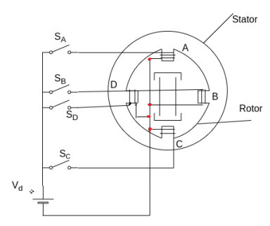
Fig 13 Single Stack type Stepper Motor
When the stator phases are excited in a proper sequence from DC source with the help of semiconductors switches a magnetic field is produced.
The ferromagnetic rotor occupies the position which presents minimum reluctance to the stator fields.
That is the rotor axis aligns itself to the stator field axis.
Working-: When winding A is energized, the rotor aligns with the axis of phase A. The rotor is stable in this position and cannot move until phase A is de-energized.
Next phase B is excited and A is disconnected. The rotor moves through 90° in a clockwise direction to align with the resultant air-gap field which now lies along the axis of phase B.
The magnitude of step angle for any PM or VR stepper motor is given by

Where 
 number of stator phases or stack
 =number of the rotor teeth
Or 
Where.  = stator poles
The step angle can be reduced from 90° to 45° by exciting phases in the sequence A, A+B, B, B+C, C, C+D, D, D+A, A
A lower number of step angles can be obtained by using a stepping motor with more number of poles on stator and teeth on rotor.
b) Multi stack variable reluctance stepper motor
A Multi stack variable reluctance stepper motor can be considered to be made up of ‘m’ identical single stack variable reluctance motors with their rotors mounted on a single shaft.
The stator and the rotors have the same number of poles and therefore same pole pitch.
For m-stack motor, the stator poles in all ‘m’ stacks are aligned but the rotor poles are displaced by 1/m of the pole pitch angle from one another.
All the stator pole windings in a given stack are excited simultaneously and therefore the stator windings of each stack form one phase. Thus, the motor has the same number of phases as the number of stacks.
The figure shows the cross-section of a three stack motor parallel to the shaft. In each stack, stators and the rotors have 12 poles. For a 12 pole rotor, the pole pitch is 30, and therefore the rotor poles are displaced from each other by one-third of the pole pitch or 10°.
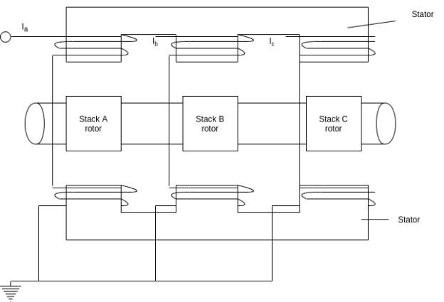
Fig 14 Multi-stack type Stepper Motor
Let  be the number of the rotor teeth and m the number of stacks or phases.
Tooth pitch  Step angle =
 Step angle=
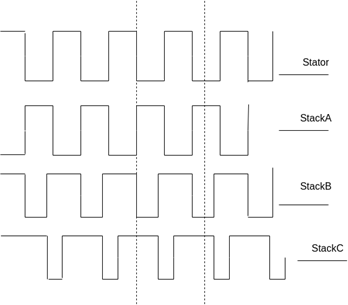
Fig 15 Number of stacks and phases
2) Permanent magnet stepper motor
The stator of a permanent magnet stepper motor is similar to that of a single stack variable reluctance motor. Rotor is cylindrical and consists of radially magnetized permanent magnets.
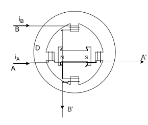
Fig 16 Permanent Magnet Stepper Motor
The above figure shows a two-pole permanent magnet stepper.
When phase A is excited with the direction of current  as shown, north pole of the rotor aligns with the phase A pole on the left. The router turns through 90° when excitation is switched from phase A to B. The direction of rotation depends on the direction of current in phase B. When
  a positive is the rotor turns clockwise and when negative it turns anticlockwise. Thus, polarities of windings current determine the direction of rotation and for bidirectional operation provision has to be made for the supply of current in either direction.
Comparison with variable reluctance motor
Due to permanent magnet the rotor, it has high detent torque and produces higher torque per ampere of stator current and because of higher the rotor volume, it has higher inertia and lower torque to inertia ratio. Therefor it has slower acceleration and response.
The maximum stepping rate for permanent magnet stepper motors is around 300 pulses per second. Whereas it can be as high as 1200 pulses/sec for variable reluctance motors.
Because of difficulty in manufacturing small permanent magnet the rotor with a large number of poles is the permanent magnet stepper motor is restricted to larger step sizes in the range of 30-90°.
Advantages
1) They are compatible with digital systems.
2) A wide range of step angles is available off-the-shelf from most manufacturers, in the range of 1.8 to 90°.
3) Bi-directional control is available.
4) Maximum torque occurs at low pulse rates. The stepper motor can, therefore, accelerate its load easily.
5) Low speeds are possible without A reduction gear.
6) The starting current is low.
Disadvantages
1) Efficiency is low.
2) Proper matching between the load, motor and its drive is required.
Torque vs stepping rate characteristics
As the stepping rate increased, the rotor has less time available to drive the load from one position to the next. Beyond a certain pulsing rate, the router cannot follow the command and begins to miss pulses.
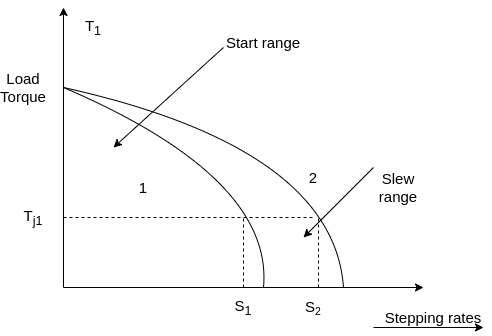
Fig 17 Torque V/S Stepping Rate Characteristics
If the values of load torque and pulsing rate are such that the point of operation lies to the left of the curve I, then the motor can start and also synchronize without missing a pulse if the stepping rate less than 
Once the motor has started and synchronized, the stepping rate can be increased for the same load torque without missing a step. For load torque  after starting and synchronization, the stepping rate can be increased up to
  without missing a step or without losing synchronism.
However, if the stepping rate is increased beyond  then the motor will lose synchronism.
Key takeaway
The stepper motor has a rotor movement in discrete steps. The angular rotation is determined by the number of pulses fed into the control circuit. Each input pulse initiates the drive circuit which produces one step of angular movement. Hence, the device may be considered as a digital to analog converter. The types of the stepper motor,
- Variable reluctance
- Permanent magnet
- Hybrid type
Permanent magnet DC motor-
The basic working principle of DC motor is based on the fact that whenever a current-carrying conductor is placed inside a magnetic field there will be mechanical force experienced by that conductor.
In these motors, the magnetic field is established by means of a magnet. The magnet can be of any types i.e., it may be an electromagnet or it can be a permanent magnet.
Construction-
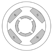
Fig 18 PMDC Motor
A PMDC motor mainly consists of two parts. A stator and an armature. Here the stator which is a steel cylinder. The magnets are mounted in the inner periphery of the cylinder. The permanent magnets are mounted in such a way that the N-pole and S-pole of each magnet are alternatively faced towards armature.
In addition to holding the magnet on its inner periphery, the Steel cylindrical stator also serves as a low reluctance return path for the magnetic flux.
Although field coils are not required in permanent magnet DC motor but still, it is sometimes found that they are used along with permanent magnet. This is because if permanent magnet loses their strength, these lost magnetic strengths can be compensated by field excitation through these field coils.
The rotor of the PMDC motor is similar to other DC motors.
Equivalent circuit:
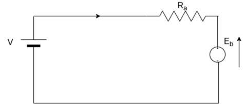
Fig 19 Equivalent Circuit
As in PMDC motor, the field is produced by a permanent magnet, there is no need for drawing field coils in the equivalent circuit of permanent magnet DC motor.

Advantages-
1) No need for field excitation arrangement.
2) No input power is consumed for excitation which improves the efficiency of DC motor.
3) No field coil hence space for field coil is saved which reduces the overall size of the motor.
4) Cheaper and economical for fractional KW rated applications.
Disadvantages-
1) In the case of armature reaction of DC motor cannot be compensated hence the magnetic strength of the field may get weak due to demagnetizing effect.
2) Due to excessive armature current, there is a chance of getting the poles permanently demagnetized (during starting, reversal, overloading condition)
3) The field in the air gap is fixed and limited and it cannot be controlled externally. Therefore, very efficient speed control of DC motor in this type of motor is difficult.
Applications-
PMDC motor is extensively used where small DC motors are required and also very effective control is not required, such as in automobiles starter, toys, wipers, washers, hot blowers, air conditioners, computer disk drives and in many more.
Permanent magnet AC motor
In PMAC motor, magnets mounted on or embedded in the rotor coupled with the motor's current-induced internal magnetic fields generated by electrical input to the stator.
PMAC motor has a sinusoidally distributed stator winding to produce sinusoidal back EMF waveforms.
All PMAC motors require a matched PM drive for operation. They are not designed for across the line starting.
In PMAC motors rotate at the same speed as the magnetic field produced by the stator windings it is the synchronous machine.
PMAC motors are suitable for variable or constant torque applications, where the drive and application parameters dictate to the motor how much torque to produce at any given speed.
Limitations and challenges-
PMAC speed is limited by back EMF because of the latter increases directly with motor speed.
The motor is connected to the electronic drive and its electronic components are designed for a maximum voltage above rated drive voltage.
Key takeaway
A PMDC motor mainly consists of two parts. A stator and an armature. Here the stator which is a steel cylinder. The magnets are mounted in the inner periphery of the cylinder. The permanent magnets are mounted in such a way that the N-pole and S-pole of each magnet are alternatively faced towards armature.
Case Study
Driver Circuit for Stepper Motor
Steppers are special motors that do not have any commutator to reverse flow of the windings current. Stepper motors are the best alternatives for applications that high-accuracy motions are required such as CNC, printers and so on. Because of the simple winding and control system, the main applications of these motors are the motion controls. On the basis of the motor structure and operation, stepper motors are divided into three types: permanent magnet (PM), variable reluctance (VR) and hybrids. There is special procedure for driving each of them. In general, stepper motors are driving in full-, half- and micro-step modes. In full-step mode, to change rotor position completely, activation and deactivation signals are fed to the windings alternatively in each cycle.
In half-step, each winding can stay activated for more than on cycle. Therefore, the rotor motion is half of the full-step and the motor resolution is two times more. Micro-step driving is another alternative for motor motion that has more accuracy and continuous motion. Two main advantage of micro-step mode is the possibility for rotor to move between full and half modes and to eliminate irregular characteristics of motor torque. Stepper motor driver circuit implementation process for all three modes is
Presented. For design testing, appropriate driving signal patterns are generated using PC parallel port. Torque tests are applied to the driver circuit and experimental results extracted. As obtained, using micro-step driving, stepper motor rotates more continuously. Also, irregular torque values (appeared like holes in torque curve at resonance frequencies) are eliminated.
Control Circuit
Generally, control and driving techniques for stepper motors are categorized in open- and close-loop modes (here, open-loop mode is considered). In stepper motors, driving is done by activation and deactivation of various windings. In general stepper motor driver circuit is divided into two main parts: signaling and switching [8]. Signaling part is for generating the consequent and regular pulses (patterns) for motor driver. The switching part turns the control switches on and off according to the generated patterns. A four-phase stepper motor
Driver has two main parts as follows: control signal sequencer and motor driver
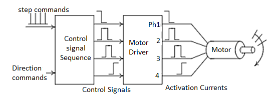
Fig: Driver Circuit
According to the nature of the windings, the current and therefore the switch state could not change suddenly except that infinite opposite voltage is applied to the winding. When the control switch of the winding is closed, the winding current increased gradually. Thus, when its state change (the switch opened), large voltage is applied to the winding. This may damage the control switches if there is no care about it. There are two main strategies to solve these problems: using diode or capacitance in parallel with the
Winding. There are several driving techniques for every type of the stepper motors. Consider a bipolar H Bridge hybrid motor, as shown in Fig2. Reversing the magnet field direction, one can change the winding current flow. Achieving this, one can arrange the control switches like H letter (called H-Bridge) and
Put the winding between them.
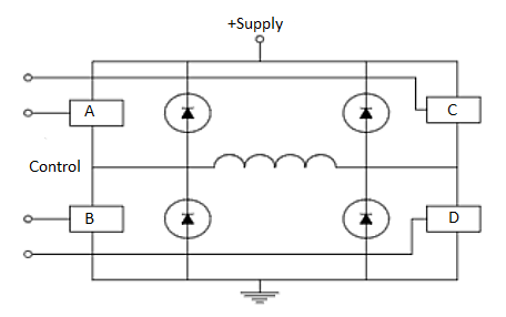
Fig: Bridge Hybrid Model
Because of four control switches, H-Bridge can have 16 different modes of operations. Some of
Them are not used generally. Some of the practical operation modes are as follows
- Forward: only A and D switches are closed.
- Reverse: only B and C switches are closed.
- Fast Decay: All switches are closed and the winding current decreased through the power
- Supply and diodes path. This mode doesn’t damage the winding and therefore the rotor can move freely without any resistance.
- Slow Decay: In this mode, the current is passed through the motor winding rotationally without any resistance. Therefore, if a few current remains in winding, this operation caused the current dissipated and the rotor stopped slowly.
It is possible that activation of control switches in H-Bridges caused short-circuit between power supplies (i.e., closing switches A and B). In these cases, usually logic gates used to eliminate short-circuit effects. Fig shows the sample circuit where this technique is applied.
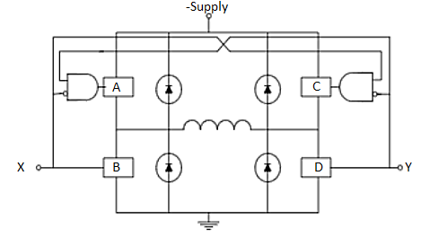
Fig: SC elimination from H bridge
As shown above, all of the operation modes can be accessible only with a few numbers of signals.
This is so practical when we use microcontrollers or microprocessors for control signal (pattern)
Generation (i.e., X and Y signals on the above).
Micro-step driving circuit
In micro-step mode, the resolution (number of steps per round) is increased. The motor used pass 1.8 degree per rotation and has resolution equals to 200 steps. After micro-step driving, the target becomes 800 steps per rotation (4 micro-steps per each step). After driver implementation for half- and full-step
Modes, several parts should be changed and optimized for micro-step driving. One of the main parts is the reference voltage (Vref). Another optimization is to control two phases of the motor independently. For this purpose, driver circuit must be changed to be able to control the winding current independently to the portion of the final phase current. For this, one can control the current of the motor phases to be able to move between two full steps more. According to this, digital to analog converter (DAC) and operational amplifiers (OpAmp) are used to control the reference voltage of the motor. Inputs to the ADC will determined the signal levels and the bit number can perform more accurately. Two L297 devices are used to control the L298 phases separately. These devices should be synchronized by each other. The inhibit output signals of each L297 (INH) control corresponding enable (EN) lines of the L298 (ENA and ENB).
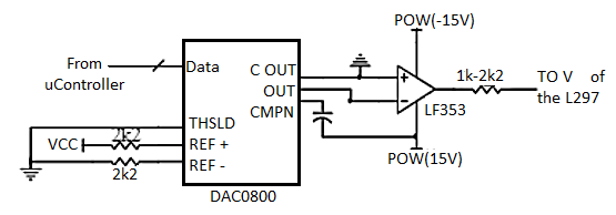
Fig: Micro-step driving circuit
References:
- M.G. Say, Performance and Design of A.C. Machines (3rd Ed.), ELBS
- J B Gupta - Theory and performance of Electrical Machines, S K Kataria Publications
- Samarjit Ghosh, Electrical Machines, Pearson Publication.
- Bhag S Guru and Huseyin R Hiziroglu, Electrical Machinery and Transformer, 3rd Edition, Oxford University Press.
- E G Janardanan, Special Electrical Machines, Prentice Hall of India.
- Suvarnsingh Kalsi Application of high-Temperature superconductors to electric power equipment (Rotating Machines) Wiley publication.