Unit - 5
AC series motor
AC series motor are also known as the modified DC series motor as their construction is very similar to that of the DC series motor.
What will happen when we give an AC supply to DC series motor?
1) An AC supply will produce a unidirectional torque because the direction of both the currents (i.e., armature current and field current reverses) at the same time.
2) Due to presence of alternating current, Eddy currents are induced in the yoke and field course which result in excessive heating of the yoke and field cores.
3) Due to the inductance of the field and the armature circuit, the power factor would become very low.
4) There is sparking at the brushes of the DC series motor.
Key takeaway
The DC series motor cannot operate efficiently on AC supply.
Thus, considering above points we can say that we don't have good performance of DC series motor on the application of AC supply. There need some modifications
a) In order to reduce the Eddy currents there is need to laminate the yoke and field core.
b) The power factor is directly related to reactance of the field and armature circuit and we can reduce the field winding reactance by reducing the number of turns in the field winding. But on reducing the number of turns, field MMF will decrease and due to this the air gap flux will decrease. The overall result of this is that there is an increase in the speed of the motor but decrease in the motor torque which is not desired.


The solution to this problem is the use of compensating winding.
c) The number of armature conductors is increased in order to get the required torque with the low flux.
Key takeaway
There are eddy current losses and lamination is required to reduce them. The torque developed is given as

Examples
Q1) Determine torque established by the armature of six pole DC motor having 680 conductors, two paths in parallel, 24mWb flux/pole and armature current 50A?
Sol: 

T= x24x10-3x50x680x (4/2) =259.74 N-m
Q2) A 220V DC Shunt motor runs at 450rpm when armature current is 39A. Calculate speed if the torque is doubled. The armature has a resistance of 0.2 ohm?
Sol: Ta α φIa
Ta1 α φIa1 and Ta2 α φIa2
2= Ia2/39
Ia2=78A
N2/N1=Eb2/Eb1
Eb1=220-(39x0.2) =212.2Volts
Eb2=220-(78x0.2) =204.4Volts
N2/450=204.4/212.2
N2=433.46 rpm
Q3) A 4 pole, 210 V shunt motor has 450 lap wound conductor. It takes 32 A from supply mains and develops output power of 4.5 kW. The field takes 1 A. The armature resistance is 0.09 ohm and flux per pole is 30 mWb. Calculate speed and torque.
Soln. Ia = 32-1 = 31 n
Eb = V – Ia Ra = 210 - (0.09×31) = 207.21 V


N = 920.9 rpm


Q.4 A 220 V, dc shunt motor has an armature resistance of 0.3 ohm and field resistance of 105 ohm. At no load speed is 1200 rpm and armature current is 2.3 A on application of rated load speed drops to 1120 rpm. Find the current and power input when motor delivers rated load.
Soln. N1 = 1200 rpm Eb1 = 220 – (0.3×2.3) = 219.31 V
N2 = 1120 rpm Eb2 = 220 – 0.3 Ia2


Ia2 = 37.93 A
Line current = Ia2 + Ish = 37.93 + (220/105) = 40 A
Power input = 220 × 40 = 8800 W
Q.5 A 230 V shunt motor runs at 1000 rpm at no load and takes 6A. The total armature resistance is 0.2 ohm and field resistance is 210 ohms. Calculate the speed when loaded and taking 40 A. Assume flux constant.
Soln. 


Q.6 The armature resistance of a 15 kW, 230 V series motor is 0? 1 ohm, the brush voltage drop is 3 V and series field resistance is 0.05 ohm. The motor takes 60 A speed is 600 rpm. Calculate speed when current is 100 A.
Soln.


Φ1  60
60
Φ2  100
100


N2=350.22 rpm
Q.7 A 230V DC Shunt motor takes 4A at no load when running at 600 rpm. The field resistance is 100 ohms. The resistance of armature at standstill gives a drop of 6V across armature terminals when 10A were passed through it. Find i) Speed at no load (ii) Torque. Normal input of motor is 6kW
Sol:
i)Speed 
Ish=  =2.3A
=2.3A
F.L Power=6000
F.L line current=  =26.08A
Ia=26.08-2.3=23.78A
Ra= =0.6Ω
=0.6Ω


N=566.2 rpm
Ii)Torque  =
=

Construction-
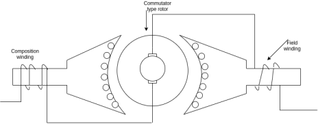
Fig 1 Construction of Series Motor
The armature of AC series motor is same as ordinary series motor. In order to minimize commutation problems, high resistance brushes with increased brush area are used. The stator core and yoke are laminated to reduce Eddy current loss produced by alternating flux. The machine is generally operated at a lower flux density using very short air gaps.
- Conductively compensated type motors
In this type of motor, the compensating winding is connected in series with the armature circuit. The winding is put in the stator slots. The axis of the compensating winding is 90° with the main field flux.
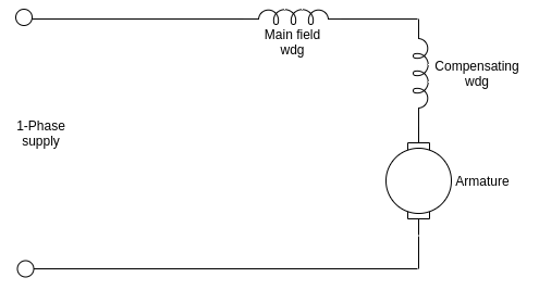
Fig 2 Conductively compensated type motor
b. Inductively compensated type motors
In this type of motor, the compensating winding has no interconnection with the armature circuit of the motor.
In this case a transformer action takes place as the armature winding will act as primary winding of the transformer and the compensating winding will acts as a secondary winding.
The current in the compensating winding will be in phase opposition to the current in the armature winding.
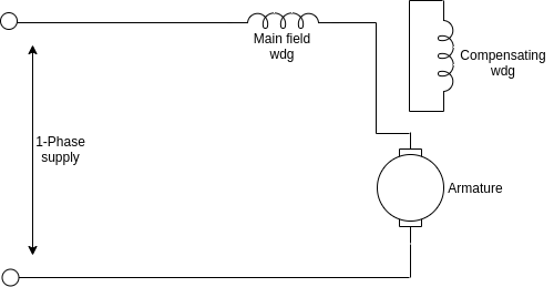
Fig 3 Inductively compensated type motor
Complete schematic diagram of the single-phase AC series motor with all the modifications.
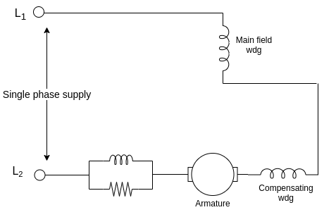
Fig 4 AC Series motor
The main function of the inter poles is to improve the performance of the motor in terms of higher efficiency and a greater output from the given size of the armature core.
Key takeaway
In this conductively compensated type, the compensating winding is connected in series with the armature circuit.
In inductively compensated type motor, the compensating winding has no interconnection with the armature circuit of the motor.
Phasor diagram
The circuit diagram of a compensated AC series motor is shown in figure. The MMF produced by the compensating winding opposes the quadrature axis mmf produced by the armature current.
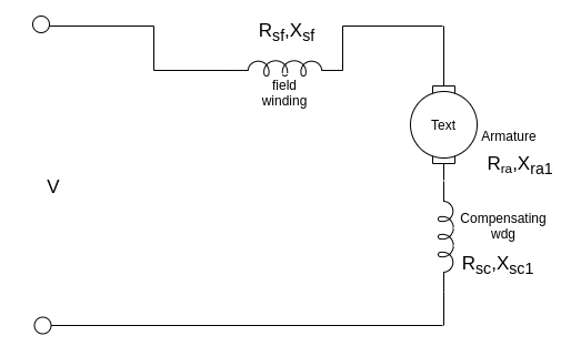
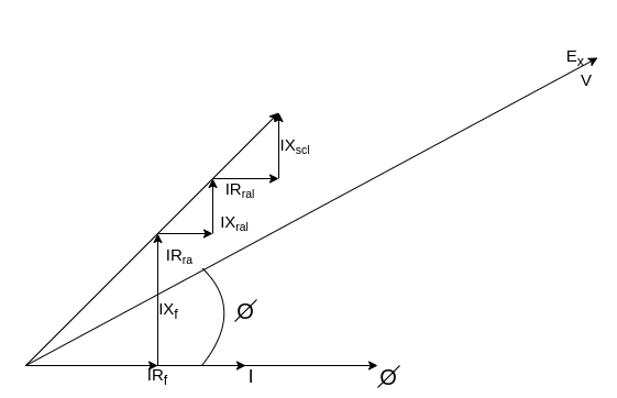
Fig 5 Phasor Diagram
Where
 =field resistance
 = field reactance due to its self inductance
 = armature resistance
 =armature leakage reactance
 =compensating winding resist.
 = leakage reactance of compensator.
 = rotational EMF
If the same motor is supplied with DC, the voltage equation is given by

This method for improving commutation in the coil undergoing commutation with the help of small poles fixed to yoke is done by reversing the emf required to neutralise the reactance voltage. In practice these poles are placed in between main poles. There are heavy copper wires wounded and are connected in series to the armature. The polarity of this interpole is kept same as that of the next main pole coming in the direction of the rotation. The coil sides lie under the interpoles by placing brushes along the GNA.
As the main poles and inter poles have same polarity the emf induced helps in quick reversal of current. The commutating or reversing emf is induced in the interpoles. This helps to neutralize the reactance voltage making sparkless commutation.
The commutation up to 20-30% can be achieved by this method. In this case the sparling and heating limit are in same range. The machine can be designed smaller for a given output making it cost effective than non-interpoles machines.
The neutralization of reactance voltage at all loads can be achieved by using interpoles. The reversing emf’s are proportional to the armature current as the interpoles are connected in series with the armature and reactance.
With production of reverse emf opposite to reactance voltage the interpoles also helps to neutralizing cross magnetizing effect of armature reaction. But there is difference between compensating winding and interpoles. The two are connected in series and both will try to neutralize armature reaction effect. But interpoles in addition supply reversing e.m.f. To improve commutation. In addition to this, the action of interpoles is localized near the commutation area only. It has negligible effect on armature reaction occurring on the remaining part of the armature periphery.
Key takeaway
This method for improving commutation in the coil undergoing commutation with the help of small poles fixed to yoke is done by reversing the emf required to neutralise the reactance voltage. In practice these poles are placed in between main poles. There are heavy copper wires wounded and are connected in series to the armature.
Single phase AC series motor has high starting torque. They are used in electric Railways with power ratings to 2200 HP, voltage range from 220 V to 600 V and frequency from 15 to 25 Hz.
Fractional horsepower single phase AC series motor are used for domestic and industrial application.
For such applications, motors of rating 115 V to 230 V, frequency of to 60 Hz and speed 3000 rpm to 18000 rpm are used.
Example
A universal series motor has a resistance of 30 Ω and an inductance of 0.5 H. When connected to a 250 V DC supply and loaded to take 0.8A it runs at 2000 rpm. Determine the speed, torque and power factor when connected to a 250 V, 50 Hz AC supply and loaded to take the same current.
Answer-
-> Operation of motor on DC

=250-0.8×30
=226 V

Operation of motor on AC


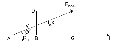
From the phasor diagram


Since currents in dc and ac operation are equal, the flux will also be equal (


Power factor=

 lagging
Mechanical power developed


Torque developed


A series motor designed for operation on DC does not show good performance when operated on AC.
Small fractional bp what is known as universal motors are widely used for food mixers, vacuum cleaners, hair dryers, electric shavers, portable drills, sewing machines etc.
They are ac series motors generally without compensating winding and can be used on both AC and DC.
They have ratings: below 0.75 HP and have high operating speed of around 7000 rpm or so.
The high speed results in a small weight and size of the motor. The friction and windage losses are sufficient to limit the no load speed to a safe value.
Armature current is small, so that serious commutation problems are eliminated.
Phasor diagram-
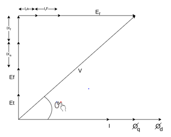
In a universal motor the q axis field created by armature current is also present in addition to the Direct axis field  created by the series field winding.
In an AC series motor with compensating winding the q axis field is neutralized by the effect of compensating winding.
Both these fields alternate at supply frequency. Each of these field sets up rotational EMF and transformer EMF.
The d axis flux  creates a rotational EMF across the brushes.
In a DC machine this EMF E is

Where  =Flux per pole
Z=number of armature conductors
P=number of poles
A=number of parallel paths
n= speed, revolutions/second
The frequency corresponding to speed n is 
Therefore,

If flux  is alternating i.e.,
  , the instantaneous value of rotational EMF
  is
is

And the rms value  is
is

This EMF is in phase with flux 
Since flux  is alternating flux, transformer EMF is also induced in armature coils. This EMF adds to zero at the brushes.
The q axis flux  (created by armature coils) also sets up rotational and transformer EMFs. The transformer EMF due to this flux
  Is
Is

Where
 =RMS value of transformer EMF, volts.
f=supply frequency
 =breadth factor (since the armature winding is distributed in slots)
If 

Since  is alternating at the supply frequency f, it induces a transformer EMF in the field winding which is a concentrated winding of
  turns. This EMF is given by

This EMF is in quadrature with flux  therefore,
  and
and  are in phase. Both these EMF are proportional to and in quadrature with current I. Therefore, it is possible to write
  , where X is a constant of proportionality and has the dimensions of reactance.
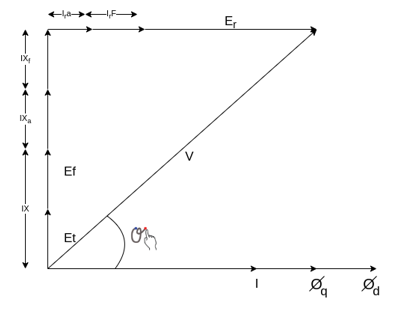
Fig 6 Phasor Diagram of Universal Motor
Example
A 2 pole, 50 HZ, 230-volt universal motor has 1200 armature turns and 400 series field turns. When operated on AC, the full load current is 1 A, field flux is 0.0008 weber and speed is 7000 rpm. The total resistance and leakage reactance are 20 ohm and 30 ohm respectively. Find
a) Transformer EMF induced in the armature winding by the quadrature flux
b) Quadrature flux
c) HP output
d) Speed of operation if machine is connected to DC supply and takes 1 A. The armature is wave wound.
Solution->
a) 
A=2, Z=1200*2,


=158.37V


=71V
The phasor diagram is shown below


b) 


c) 

=0.814
 lagging
Power input=


Copper losses =

Neglecting other losses=power output=178.48-20
=158.48 watt

When connected to DC supply


=230-20
=210V


=9282 rpm
4. The motor of above example is provided with a compensating winding having a resistance of 2 ohm and reactance of 5 ohm. The compensating winding neutralizes armature flux completely. Find the speeds of operation on AC and DC if V=230V and I=1A
Since  has been neutralized fully


If  is the new speed for AC operation


When connected to DC supply


5. A universal series motor has a resistance of 30 and an inductance of 0.5 H. When connected to a 250 V dc supply and loaded to take 0.8 A it runs at 2000 rpm. Determine the speed, torque and power factor, when connected to a 250 V, 50 Hz ac supply and loaded to take the same current.
Operation of motor on dc
Ebdc = V-IaRa = 250-0.8 x 30 = 226V
Ndc = 2000rpm
Operation motor on ac
XL = 2πfL = 2πx 50x0.5=157
From phasor below we get
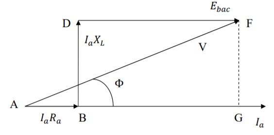


Since the currents in dc and ac operation are equal, the flux will also be equal ɸac= ɸdc


Power factor  (lagging)
Mechanical power developed

Torque developed

AC Motors | DC Motors |
Ac motors are powered from AC current. | DC motors are powered from DC current. |
In AC motors conversion of current is not required | In DC motors conversion of current is required like ac into dc current |
AC motors are used where power performance is sought for extended periods of time. | DC motors are used where motor speed required to be controlled externally. |
AC motors can be single phase or three phase. | All DC motors are single phase. |
In AC motors Armatures do not rotate while magnetic field continuously rotates. | In DC motors, the armature rotates while magnetic field does rotate. |
Repairing of DC motors is costly. | Repairing of AC motors is not costly. |
AC motor does not use brushes. | DC motor uses brushes. |
AC motors have a longer life spam. | DC motors have not a longer life spam. |
Speed of AC motors is simply controlled by varying the frequency of current. | Speed of DC motors is controlled by varying the armature winding's current. |
AC motors require an effective starting equipment like capacitor to start operation. | DC motors do not require any external help to start operation |
Case Study
Implementation of Controllers for Speed Control of DC Motor
Conventional PID controllers are used to control the dc motor for various industrial processes from many years due to their simplicity in operation. In industrial area the of PID controller used in various level to improve efficiency of the industries or plant. A PID controller requires controlling the plant for different process and control applications. In this paper worked out, speed control analysis of DC motor using PID controller & Speed control of separately excited dc motor has done with using armature voltage control method. So that PID controller basics are verified and various tuning methods of PID controller are explained and the mathematical modeling of dc motor has done and it is simulated to Simulink. The control system consisting of PID controller dc motor is also simulated to Simulink. Response of dc motor is recorded as simulation result when step input to provide as reference signal. Therefore, the performance and analysis of dc the motor with PID controller is performed and calculating the various responses of the parameters such as maximum overshoot, rise time, settling time, etc.
DC machine are highly versatile and flexible machine. It has to satisfy demands of load requiring of high starting, torque accelerating and retarding torques. A dc machine is also easily adaptable for drives with range of speed control and fast reversal. They are widely used in industrial applications. The DC motors are used in rolling mills, in traction and in overhead cranes. They are also employed in many control applications as actuators and as speed or position sensors. In such applications, are such as position sensors and robotics, drives‟ performance must precisely follow the desired performance. A number of control schemes such as proportional (P), proportional integral (PI), proportional derivative integral (PID), adaptive and fuzzy logic controller (FLCs) are used for control the speed of DC motors. The proposed controller system uses the PID control scheme for speed control of dc motor.
Almost every mechanical movement that we have seen around of accomplished by an electric motor. Electric machines means of converting energy. Motors take electrical energy and produce mechanical energy. Electric motors are used to power hundreds of the devices and we use in everyday in life. Motor comes are in various sizes. Huge motors that can take loads of 1000’s of Horsepower are typically used in the industry. Some examples of the large motor applications include elevators, electric trains, hoists, and heavy metal rolling mills. Examples of small motor applications include motors used in automobiles, robots, hand power tools and food blenders. Micro-machines are electric machines with parts the size of red blood cells, and find many applications in medicine.
Electric motors are broadly classified into two different categories: DC (Direct Current) and AC (Alternating Current). Within these categories are numerous types, each offering unique abilities. In most of the cases, regardless of type, electric motors consist of a stator (stationary field) and a rotor (the rotating field or armature) and operate through the interaction of magnetic flux and electric current to produce rotational speed and torque. DC motors are distinguished by their ability to operate from direct current. There are different kinds of D.C. Motors, but all work on the same principles. In this paper, we will study their basic principle of operation and their characteristics. It has to understand motor characteristics so we can choose the right one for application requirement.
DC motors consists of one set of coils, called armature winding and inside another set of coils or a set of permanent magnets, called the stator. Applying a voltage to the coils produces a torque in the armature, resulting in motion. The stator is the stationary part of a Dc motor. Whereas stator has made of Permanent magnet Dc motor is composed of two or more permanent magnet pole pieces. The magnetic field can alternatively be created by an electromagnet. In this case, a DC coil (field winding) is wound around a magnetic material that forms part of the stator. The rotor is the inner part of the dc motor and rotor is composed of windings are (called armature windings) which as connected to the external circuit through a mechanical commutator. Whereas stator and rotor are made of ferromagnetic materials
A winding is made up of series or parallel connection of coils. It may be two types namely (a) Armature winding - The winding through which the voltage is applied or induced. (b) Field winding - The winding through which a current is passed to produce flux (for the electromagnet) Windings are usually made of copper. Electrical energy supplied conductor caring perpendicular to a magnetic field, the interaction of current flowing on the conductor and the magnetic field will be produced.
A PID controller is a control loop feedback mechanism (controller) and widely used in industrial control systems. A PID controller calculates the error value of the difference between a measured process variable and a desired set point. The PID controller algorithm involves three separate constant parameters, and is accordingly sometimes called three term control: the proportional, the integral and derivative values, may be denoted by P, I, & D. Simply put, these values can be interpreted in terms of time: P depends on the present error, I on the accumulation of past errors, and D is a prediction of future errors, based on current rate of change. The weighted sum of these three actions is used to adjust the process via a control element such as the position of a control valve.
References:
- M.G. Say, Performance and Design of A.C. Machines (3rd Ed.), ELBS
- J B Gupta - Theory and performance of Electrical Machines, S K Kataria Publications
- Samarjit Ghosh, Electrical Machines, Pearson Publication.
- Bhag S Guru and Huseyin R Hiziroglu, Electrical Machinary and Transformer, 3rd Edition, Oxford University Press.
- E G Janardanan, Special Electrical Machines, Prentice Hall of India.
- Suvarnsingh Kalsi Application of high Temperature super conductors to electric power equipments (Rotating Machines) Wiley publication.
- Essam Natsheh and Khalid A. Buragga, “Comparison between Conventional and Fuzzy Logic PID Controllers for Controlling DC Motors,” International Journal of Computer Science Issues, Vol. 7, Issue 5, September 2010.
- Ankit Rastogi and Pratibha Tiwari, “Optimal Tuning of Fractional Order PID Controller for DC Motor Speed Control Using Particle Swarm Optimization,” International Journal of Soft Computing and Engineering, Volume-3, Issue-2, May 2013.