Unit 6
Single-phase induction motor
Single-phase induction motors are small size motors of fractional kilowatt ratings. Domestic appliances like fans, hair dryers, washing machines, vacuum cleaners, mixers, refrigerators, food processors, and other kitchen equipment employ these motors. These motors also find applications in Air conditioning fans, blowers, office machinery, small Power tools, dairy machinery, small farming equipment, etc.
A single-phase induction motor consists of a single-phase winding mounted on the stator and a cage winding on the rotor. When a single-phase supply is connected to the stator winding a pulsating magnetic field is produced. Under these conditions, the rotor does not rotate due to inertia. Therefore, the single-phase induction motor is inherently not self-starting and requires some special starting means.
If, however, the single-phase stator winding is excited and the rotor of the motor is started by an auxiliary means, and the starting device is then removed, the motor continues to rotate in the direction in which it is started.
Consider two windings a, b so displaced that they produce magnetic fields 90° apart in space.
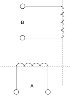
Fig 1 Winding A and B producing 900 apart magnetic field
Suppose that these windings produce magnetic fields equal in magnitude and 90° apart in the time given by


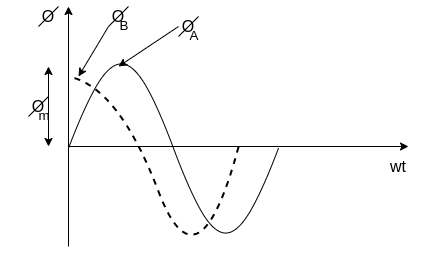
Fig 2 Magnetic field 900 apart on time
The resultant of these fields is the rotating magnetic field of constant magnitude  . This rotating magnetic field may be represented by a phasor constant magnitude
  .
.
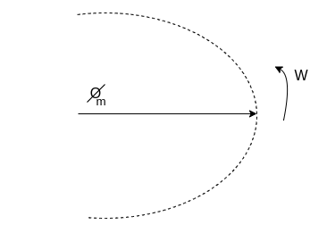
Fig 3 Phasor of Rotating Magnetic Field
Key takeaway
Single-phase induction motors are small size motors of fractional kilowatt ratings. Domestic appliances like fans, hair dryers, washing machines, vacuum cleaners, mixers, refrigerators, food processors, and other kitchen equipment employ these motors
The double-revolving field theory of single-phase induction motors states that a stationary pulsating magnetic field can be resolved into two rotating magnetic fields, each of equal magnitude but rotating in opposite directions. The induction motor response to each magnetic field separately and the net torque in the motor is equal to the sum of the torques due to each of the two magnetic fields.
The equation for an alternating magnetic field whose axis is fixed in space is given by

Where  is the maximum value of the sinusoidally distributed air-gap flux density produced by a properly distributed stator winding carrying an alternating current of frequency
  is space displacement angle measured from the axis of the stator winding.


The first term on the RHS represents the equation of a revolving field moving in the positive  direction. It has a maximum value equal to
The second term on the RHS represents the equation of revolving field moving in negative  direction. It has a maximum value equal to
The field moving in the positive  direction is called the forward rotating field. The field moving in the negative
  direction is called a backward rotating field.
The positive direction is the direction in which the single-phase motor is started initially.
When the rotor is stationary, the induced voltages are equal and opposite consequently two torques are also equal and opposite. Hence, at standstill, the net torque is zero. In other words, a single-phase induction motor with a single stator winding inherently has no starting torque.
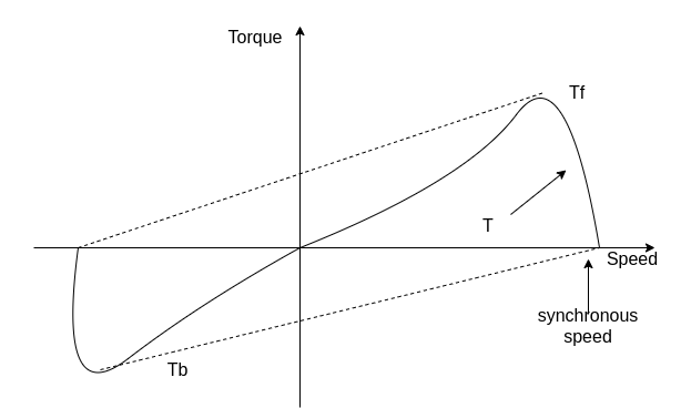
Fig 4 Torque-Speed Characteristics
Key takeaway
The double-revolving field theory of single-phase induction motors states that a stationary pulsating magnetic field can be resolved into two rotating magnetic fields, each of equal magnitude but rotating in opposite directions.
If the rotor is started by auxiliary means, it will develop torque and continue to run in the same direction as one of the fields. By definition, the direction in which the router is started initially will be called the forward field.
Let  = synchronous speed, n=rotor speed
The slip of the rotor with respect to the forward rotating field is

Since the backward rotating flux rotates opposite to the stator, the sign of n must be changed to obtain the backward slip.
Thus, the slip of the rotor with respect to the backward rotating field is


Adding 1 and 2


The first equation corresponds to a motor operation and the second equation denotes the braking region. Thus, the two torques have an opposite influence on the rotor.
The router equivalent circuits for the forward and backward rotating fluxes are shown below.

For forwarding rotating flux wave

At stands still, the impedances are equal and therefore, the current  are equal. These currents produce mmfs which oppose the stator mmfs equally. Therefore, the rotating forward and backward flux is in the air gap are equal in magnitude and no torque is developed.
However, when the rotor rotates the impedance of the rotor circuits are unequal and the rotor current  is greater than the rotor current
Since the value of S is generally small (around 0.05)  is considerable higher than
  . Therefore,
  is greater than
  and forward flux is greater than the backward flux.
However resultant flux remains essentially constant. This resultant flux induces a voltage in the stator winding. Both flux waves induce voltages in the rotor and produce torque in the rotor. These two torques are in opposite directions. The net induced torque in the motor is equal to the difference between these torques.

Fig 5 Torque and Speed Characteristics
Key takeaway
If the rotor is started by auxiliary means, it will develop torque and continue to run in the same direction as one of the fields.
Most single-phase induction motors are two-phase motors in which the auxiliary winding is disconnected from the supply when the machine reaches a certain value. The machine then operates, as a true single-phase motor running on its main winding.
Consider the rotor is stationary and only the main winding is excited. The motor behaves like a single-phase transformer with its secondary short-circuited.
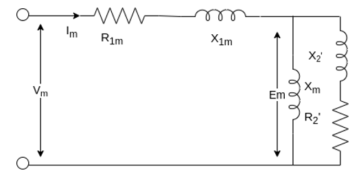
Fig 6 Equivalent Circuit
Where:
 = resistance of the main winding
 = leakage reactance of the main stator winding.
 = magnetizing reactance
 = stand Steel rotor resistance referred to the main stator winding.
 = standstill rotor leakage reactance refers to the main stator winding.
 = applied voltage
 = main winding current
The core loss branch is not shown, the core losses will be assumed to be lumped with the mechanical and stray losses as a part of the rotational losses of the motor.
According to the double-revolving field theory, the pulsating air gap flux in the motor at standstill can be resolved into two equal and opposite fluxes with the motor.
Thus, a single-phase induction motor may be considered as consisting of two motors having a common stator winding and two imaginary rotors, which rotate in opposite directions.
The standstill impedance of each rotor refers to the main stator is 
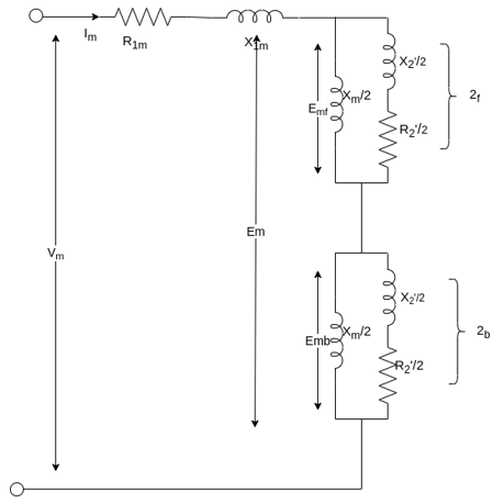
Fig 7 Standstill impedance of each rotor refers to the main stator
At standstill with the effects of forward & backward rotating fluxes. The first portion shows the effect of forwarding rotating flux, and the second portion shows the effect of backward rotating flux.

At standstill, 
Now suppose that the motor is started with the help of an auxiliary winding and the auxiliary winding is switched out after the motor gains its normal speed.
S=the slip of the rotor with respect to the forward rotating flux.
(2-S) =the slip of the rotor with respect to the backward rotating flux.
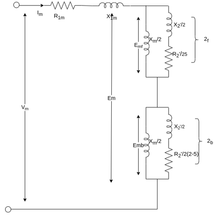
Fig 8 Simplified Circuit
For simplification


Here  =rotor impedance offered to the forward field.
 =rotor impedance offered to the backward field.


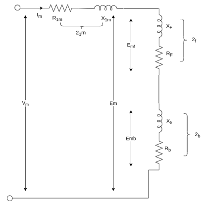
The current in stator winding is

Key takeaway
At standstill with the effects of forward & backward rotating fluxes. The first portion shows the effect of forwarding rotating flux, and the second portion shows the effect of backward rotating flux.

The torque of the backward field is in opposite direction to that of the forward field, and therefore the total air gap power in a single-phase induction motor is

Where  =air gap power for forward field

 air gap power for backward field


The torque induced by the forward field

The torque induced by the backward field

Where  =Synchronous speed in radian per second
The electromagnetic torque  is the difference between the torques


Since the rotor current produced by the forward and backward field are of different frequencies, the total rotor copper loss  is the sum of rotor copper loss due to the forward field and the rotor copper loss due to the backward field.


Since the rotor copper loss is equal to the slip times airgap power
The total rotor copper loss

The power converted from electrical to mechanical form in a single-phase induction motor is given by

Where  =angular velocity of the rotor in radian per second
Since,


Shaft output power


Where  = rotational losses
Numerical
A 230-volt 50 HZ, 4 pole single-phase induction motor has the following equivalent circuit impedances.

Friction windage and core loss =40W
For a slip of 0.03 pu, calculate
a) Input current
b) Power factor
c) Developed power
d) Output power
e) Efficiency
From the given data


For the forward field circuit


For the backward field circuit


a) Input current 

b) Power factor=Cos (-60.95°) =0.4856 lagging
c) Developed power 

=479.65W
d) Output power=
=479.65-40=439.65 watt
Input power= 
=230×5.685×0.4856
=6349W
e) Efficiency=


2. A 230-volt 50 HZ, 4 pole single-phase induction motor has the following equivalent circuit parameters  Friction and windage, core losses are 50 Watt and slip is 0.025. Calculate
a) input current
b) power factor
c) developed power
d) output power
e) efficiency


For the forward field


For the backward field


a) Input current=

b) Power factor=cos (-66.0865)
=0.4053 lagging
c) Developed power 

=347.49 watt
d) Output power= 


Input power=VI


e) Efficiency= 

=56.17%
Determination of equivalent circuit parameters-
The parameters of the equivalent circuit of a single-phase induction motor can be determined from the blocked rotor and no-load test. These tests are similar to those made on a three-phase induction motor. However, except for the capacitor run motor, these tests are performed with auxiliary winding kept open.
1) Blocked rotor test
In this test, the router is at rest. Low voltage is applied to the stator so that rated current flows in the main winding. The voltage current and power input are measured. Let  denote the voltage, current, and power respectively under these conditions.
With the rotor blocked, S=1 the impedance  in the equivalent circuit is so large compared with
  that may be neglected from the equivalent circuit. Therefore, the equivalent circuit is shown below.

Fig 9 Rotor Blocked for S=1
The equivalent impedance referred to the stator is given by


Since the resistance of the main stator winding  is already measured, the effective rotor resistance at LINE frequency is given by


The equivalent reactance  is given by

Since the leakage reactance  cannot be separated

Thus, from blocked rotor test the parameters  can be found if
  is known.
2. No-load test
The motor is run without load at rated voltage and rated frequency. The voltage current and input power are measured at no load, the slip S is very small close to zero and  is very large as compared to
The resistance  associated with the backward rotating field is so small as compared to
  that the backward magnetizing current is negligible.
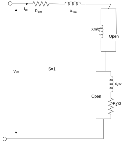
Fig 10 Circuit for No-load Test

Let  and
and  denote the voltage current and power respectively in the no-load test.

The no-load equivalent impedance is

The no-load equivalent reactance is

Resistance and Leakage Reactance Values
The copper loss is given Wcu.
Therefore,

Where, Wc = core loss
Wcu=3I2R01
Where, R01 = Motor winding of stator and rotor as per phase referred to stator.
R01=
Thus,
Let
Is = short circuit current
Vs = short circuit voltage
Z0 = short circuit impedance as referred to stator
Z01= =
=
Therefore,
X01 = Motor leakage reactance per phase referred to stator will be
X01=
Stator reactance X1 and rotor reactance per phase referred to stator X2 are normally equal.
Hence,
X1=X2=
Similarly, stator resistance per phase R1 and rotor resistance per phase referred to stator R2 can be calculated as follows:
First some suitable tests are done on stator windings to find the value of R1 and then to find R2 subtract the R1 from R01
R2=R01-R1
Short Circuit Current for Normal Supply Voltage
To calculate short circuit current Isc at normal voltage V of the stator, we must note short-circuit current Is and low voltage Vs applied to the stator winding.

Key takeaway
No-load test
W0 = VLI0cosφ0
Core loss = 3GoV2
Blocked Rotor Test:
Z01= =
=
X1=X2=
X01=
Que A 220V, single-phase induction motor gave the following test results.
Blocked rotor test: 120 V; 9.6 A, 460 W
No-load test: 220V, 4.6 A, 125 W
The stator winding resistance is 1.5 Ω and during the blocked rotor test, the starting winding is open. Determine the equivalent circuit parameters. Also find the core, friction, and windage losses.
- Blocked rotor test


2. No-load test


=0.1235


Que: A 110V, 3-phase star connected induction motor takes 25A at a line voltage of 30V with rotor locked. With this line voltage power input to motor is 400W and core loss is 30 W. The dc resistance between the pair of stator terminals is 0.1 ohm. If ratio of ac to dc resistance is 1.6. Find equivalent leakage reactance per phase and stator and rotor resistance per phase?
Sol: S.C voltage/phase= 30/ =17.3V
Is=25A/phase
Z01=17.3/25=0.7ohm/phase
Stator and cu loss=400-30=370W
3 x 252xR01=370
R01=0.197ohm
Leakage reactance/phase X01= =
= =0.67ohm
Dc resistance/phase stator=0.1/2=0.05ohm
Ac resistance/phase R1=0.05x1.6=0.08ohm
Effective resistance/phase rotor referred to stator  =0.197-0.08=0.117ohm
Que) In a no load test an induction motor took 8A and 440W with a line voltage of 110V. If the stator resistance/phase is 0.05ohm and frictional and windage losses are 135W. Calculate the exciting conductance and susceptance/phase?
Sol: Stator cu loss=3 R1=3x82x0.05=9.6W
Stator core loss=440-135-9.6=295.4W
Voltage/phase v=110/ V
V
Core loss=3G0V2
295.4=3 G0(110/ )2
)2
G0=0.024siemens/phase
Y0=I0/V= (8// /110=0.042siemens/phase
B0= =0.034siemens/phase
In practice some arrangement is provided in the single-phase induction motors so that the stator flux produce becomes rotating type rather than alternating type, which rotates in one particular direction only. So, the torque produced due to such rotating magnetic field is unidirectional as there is no oppositely directed torque present. Hence under the influence of rotating magnetic field in one direction, the induction motor becomes self-starting. It rotates in same direction as that of rotating magnetic field.
The following are methods to start the 1-ϕ induction motors,
- Split Phase or Resistance Start
- Capacitor Start
- Permanent Split Capacitor
- Capacitor Start Capacitor Run
- Electronic Starter for Single Phase Motor
Starting of IM
Direct on-line starter (Full voltage starting method)
In this induction motor is directly connected to the 3-phase supply. The DOL starter applies full line voltage to the motor terminals.
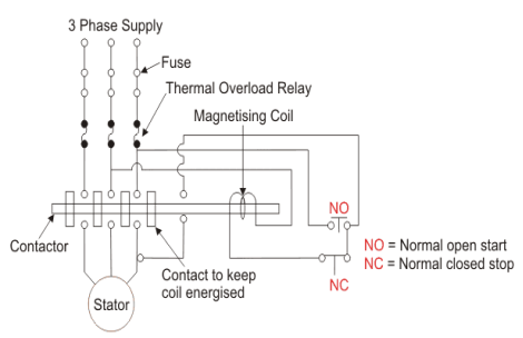
Fig11 D.O.L Starter
If the high input current does not cause any excess voltage drop in circuit than only this starter can be used. The value of armature current in motor is given as
Ia=
The expression for starting torque is given as
Ts starting torque
Tf Full load torque
If per phase rotor current at full load
Is per phase rotor current at starting
sf full load slip
ss starting slip
R2 rotor resistance
Ws synchronous speed of motor
In induction motor torque is given as
T=
The ratio of starting torque to full load torque is given as
 x sf
x sf
The wiring diagram for a DOL starter is shown above. The working principle of a DOL starter begins with the connection to the 3-phase main with the motor. The control circuit is connected to any two phases and energized from them only. When we press the start button, the current flows through magnetizing coil and control circuit also.
The current energises the contactor coil and leads to close the contacts, and hence 3-phase supply becomes available to the motor. When we stop it, the current discontinues as the supply to motor breaks the machine stops. The contactor coil (Magnetizing Coil) gets supply even though we release start button because when we release start button, it will get supply from the primary contacts as illustrated in the diagram of the Direct Online Starter.
The advantages of a DOL starter include:
- Simple and most economical starter.
- More comfortable to design, operate and control.
- Provides nearly full starting torque at starting.
- Easy to understand and troubleshoot.
- DOL starter connects the supply to the delta winding of the motor.
The reduced voltage starting methods are:
Star delta starter: The set up for star delta starter is shown below
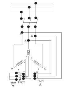
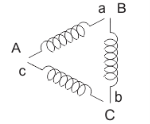
Fig:12 Star delta starter
The starter phases are connected to star by TPDT (triple pole double throw switch). Initially the TPDT switch is at position 1 and when motor attains steady state switch is thrown to position 2. In position 1 terminals are short circuited and at position 2 a, b and c are connected to B, C and A. The expression for starting torque is given as
Ts starting torque
Tf Full load torque
If per phase rotor current at full load
Is per phase rotor current at starting
sf full load slip
ss starting slip
R2 rotor resistance
Ws synchronous speed of motor
In induction motor torque is given as
T=
The ratio of starting torque to full load torque is given as
 x sf
x sf
Let V1 line voltage
Iss per phase starting current
Iss=
Starting current in stator when connected in delta position
Isd=
Isd= Iss
Iss
Then the torque ratio equation will be
 x sf
x sf
This shows that the reduced voltage method has an advantage of reducing the starting current but the disadvantage is that all these methods of reduced voltage causes, the objectionable reduction in the starting torque.
Key takeaway
The current energises the contactor coil and leads to close the contacts, and hence 3-phase supply becomes available to the motor. When we stop it, the current discontinues as the supply to motor breaks the machine stops. The contactor coil (Magnetizing Coil) gets supply even though we release start button because when we release start button, it will get supply from the primary contacts as illustrated in the diagram of the Direct Online Starter.
Depending upon the methods of producing rotating magnetic field, the single-phase induction motors are classified as
- Split phase induction motor
- Capacitor start induction motor
- Capacitor start capacitor run induction motor
- Permanent capacitor induction motor
Split phase Induction Motor (Resistance split-phase motor)
In this type of motor an auxiliary winding is connected in addition to the main winding. There is one switch called centrifugal switch (S) which disconnects the auxiliary winding from the main winding. If the starting winding has high resistance than only a phase difference can be created between these windings. The main purpose of creating this phase difference is to get the magnetic field rotated because IM cannot self-start.
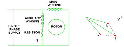
Fig:13 Split phase IM
For highly resistive winding the current is almost in phase with the voltage and for highly inductive winding the current lag behind the voltage by large angle. The starting winding is highly resistive so, the current flowing in the starting winding lags behind the applied voltage by very small angle and the running winding is highly inductive in nature so, the current flowing in running winding lags behind applied voltage by large angle. The resultant of these two currents is IT. The resultant of these two currents produces rotating magnetic field which rotates in one direction. In split phase induction motor, the starting and main current get splitted from each other by some angle so this motor got its name as split phase induction motor.
Shaded pole: This motor works I three operating regions. The poles of the motor are shaded by copper ring which are inductive. They are divided in two equal halves. The operation of such motor takes place at different flux changes:
i) When flux change from zero to positive maximum the copper band is short circuited and maximum current flows through it. This current produces its own flux. This flux opposes the main flux. So, in non-shaded part there is non uniform distribution of flux casing the magnetic axis to shift in middle of the non-shaded part.
Ii) When flux is still at its maximum and very less induced emf in the shaded portion. The main flux is not affected by the induced emf and hence, uniform flux remains.
Iii) The flux the decreases from maximum positive to zero, the current is high. The copper band is short circuited and maximum current flows through it. This current produces its own flux. This flux opposes the main flux. So, in shaded part there is non uniform distribution of flux casing the magnetic axis to shift in middle of the shaded part.
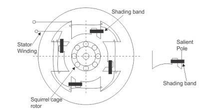
Fig:14 Shaded Pole Induction Motor
Capacitor start capacitor run IM: These two motors have same working so discussing them together. In induction motor there is no rotating flux so the motor cannot be self-started. So, a phase difference is being produced to get the rotating magnetic field. A capacitor is used to create a phase difference in this case.
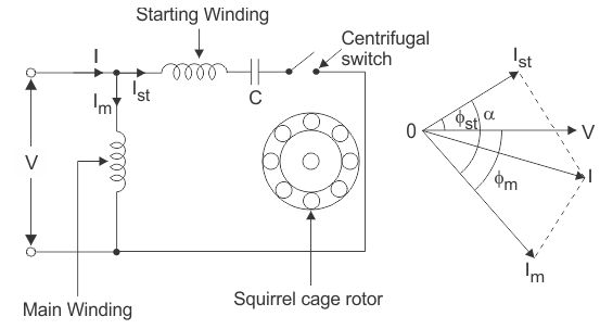
Fig 15 Capacitor Start and Capacitor Run IM
As the figure above shows we have main winding and starting winding. The capacitor is connected with the starting winding. The current Ist through the capacitor leads the voltage by some angle. The large phase difference between main winding current and starting winding current produces a resultant current I. This I generate rotating magnetic field.
These motors produce very high starting torque. In capacitor start induction motor, the centrifugal switch is provided so as to disconnect the starting winding when the motor attains a speed up to 75 to 80% of the synchronous speed but in case of capacitor start capacitors run induction motor there is no centrifugal switch so, capacitor remains in the circuit and helps to improve the power factor and the running conditions of single-phase induction motor.
Capacitor Start Motor
In these motors capacitors are the primary winding circuits which generates a greater phase difference between the current in the main and the auxiliary windings. In much easy way we can say that these motors use capacitors for starting.

Fig 16 Capacitor start Motor
These motors have cage rotor and there are two windings on stator. The two windings are called auxiliary and main windings. There is phase difference of 90o between the two windings. There is a capacitor connected in series with the auxiliary windings with a switch connected across.
As the current flowing in auxiliary winding leads the current in main winding by 900 making the single-phase current to split in two phases. The mmf in windings are having equal magnitude but are displaced by 900. This is balanced two phase motors. The auxiliary winding and the starting capacitor are disconnected by the switch when motor reaches its rated speed.
Permanent Capacitor Motor
Its connections are same as that of capacitor start and capacitor start and capacitor run motor. In series with starting winding only one capacitor is connected.
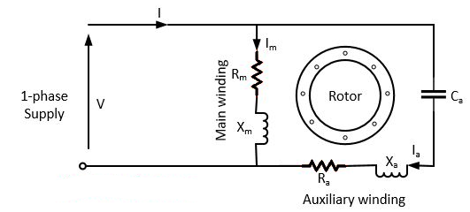
Fig 17 Permanent Split Capacitor (PSC) Motor
There is no switch in the motor because of which capacitor is connected permanently in the circuit. As no switch is there it operates in balanced two phase due to presence of auxiliary windings. It is noiseless and produces uniform torque.
Key takeaway
- No centrifugal switch is required.
- Efficiency is high.
- As the capacitor is connected permanently in the circuit, the power factor is high.
- It has a higher pullout torque.
Single phase induction motors are constructed in fractional kilowatt capacity and are used in places where three phase supply is not readily available.
Sr. No | Single phase induction motor | Three phase induction motor |
1 | Single phase induction motor develops about 50% of the output of that of three phase Motors for the same size and temperature rise. | Output of three phase induction motor is more compare two single phase induction motor for the same size and temperature rise |
2 | Single phase induction motor has lower power factor | Better power factor |
3 | The starting torque is low in single phase induction motor | Starting torque is high, also maximum torque can be obtained at starting condition |
4 | Single phase Motors are costly than 3 phase Motors of the same rating | Less costly |
5 | They are generally available up to 1 kW rating. | They are available up to 50000 kW |
Solved Numerical
Que) The stator of a 3-phase induction motor has 5 slots per pole per phase. If supply frequency is 50Hz. Calculate a) number of stator poles produced and total number of slots in stator. b) Speed of rotating stator flux.?
Sol: a) P=2n=2*5=10 poles
Total number of slots= 5 slots/pole/phase * 10 poles * 3 phase=150
a) Ns= =120x50/10=600rpm
Que) A 3-phase induction motor is wound for 5 poles and is supplied from 50 Hz. Calculate a) synchronous speed b) rotor speed when slip is 4% c) rotor frequency when rotor runs at 500 rpm?
Sol: a) Ns= =120x50/5=1200 rpm
b) rotor speed N=Ns(1-s) =1200(1-0.04) =1152 rpm
c)when rotor speed is 500 rpm, slip s=(Ns-N)/Ns=(1200-500)/1200=0.58
Rotor current frequency f’=sf=0.58x50=29.17 Hz
Que) A 3-phase, 50 Hz,3-pole induction motor has a slip of 4%. Calculate a) speed of rotor. B) frequency of rotor emf. If the rotor as a resistance of 2ohm, and standstill reactance of 4ohm, calculate the power factor c) at standstill and d) at a speed of 1200rpm?
Sol: Ns= =120x50/3=2000 rpm
a) Speed of rotor N=Ns(1-s) =2000(1-0.04) =1920 rpm
b) Frequency or rotor = f’=sf=0.04x50=2Hz
R2=2ohm, X2=4ohm
Z2=R2+jX2=2+j4=4.47 63.43o ohm
c)Power factor cosφ2=0.44(lag)
Slip at speed 1200rpm s= 2000-1200/2000=0.4
Rotor impedance at slip s=0.4 is
Z2s=R2+jsX2=2+jx0.4x4=2.56 oohm
oohm
Power factor at 1200rpm is cos φ2s=cos38.66o=0.78(lag)
Q) A 3-phase induction motor star connected rotor has an induced emf of 70volts between slip rings at standstill on open circuit. The rotor has a resistance and reactance per phase of 1ohm and 5ohm respectively. Calculate current/phase and power factor when slip rings are short circuited?
Sol: Standstill emf/rotor phase=70/
Rotor impedance/phase= ohm
ohm
Rotor current/phase=40.4/5.09=7.92A
Power factor cosφ=0.99
Que) A 3-phase induction motor star connected rotor has an induced emf of 70volts between slip rings at standstill on open circuit. The rotor has a resistance and reactance per phase of 1ohm and 5ohm respectively. Calculate current/phase and power factor when slip rings are connected to star connected rheostat of 2ohm?
Sol: Rotor resistance/phase=2+1=3 ohm
Rotor impedance/phase= =5.83 ohm
Rotor current/phase= (70/ )/5.83=6.93A
Cosφ=3/5.83=0.514
Que) A 6-pole, 3-phase induction motor operates from a supply whose frequency is 50Hz. Calculate i) speed at which the magnetic field of stator is rotating. Ii)speed of rotor when slip is 4%. Iii)frequency of rotor current when slip is 3%?
Sol: i) Stator revolves at synchronous speed. So, Ns=120f/P=120 x 50/6=1000rpm
Ii)rotor speed N=(1-s) Ns= (1-0.04) x 1000=960rpm
Iii)frequency of rotor current f’=sf=0.03 x 50=90rpm
References:
- M.G. Say, Performance and Design of A.C. Machines (3rd Ed.), ELBS
- J B Gupta - Theory and performance of Electrical Machines, S K Kataria Publications
- Samarjit Ghosh, Electrical Machines, Pearson Publication.
- Bhag S Guru and Huseyin R Hiziroglu, Electrical Machinery and Transformer, 3rd Edition, Oxford University Press.
- E G Janardanan, Special Electrical Machines, Prentice Hall of India.
- Suvarnsingh Kalsi Application of high-Temperature superconductors to electric power equipment (Rotating Machines) Wiley publication.