Unit 3
Transformers
A transformer is a stationary device which works on the principle of Mutual Induction. It is used to transform electric power from one circuit to another having same frequency. It can lower or higher the value of voltage in any circuit but in correspondence to change in current.
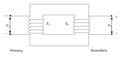
An ideal transformer has no losses i.e. its winding have no magnetic leakage and no ohmic resistance. Hence, an ideal transformer has only two purely inductive coils wound on a loss-free core.
Fig . Ideal Transformer
For above transformer when secondary is open and primary is having input sinusoidal voltage V1. An alternating current flows due to difference in potential. As primary coil is purely inductive so, Iµ current is drawn through it. This current is very small and logs V1 by 900.
The current Iµ produces magnetic flux φ and hence are in same phase. The flux is linked with both the windings and hence, self induced emf is produced E1 which is equal and opposite of V1. Similarly E2 is induced in secondary which is mutually induced emf E2 is proportional to rate of change of flux and number of secondary windings.
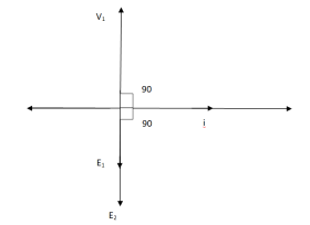
The phasor is shown below.
Phasor for Ideal Transformer
Emf Equation of Transformer :
N1 = No of primary turns
N2 = No of secondary turns
Φm = max flux in cone (wb)
Φm = Bm x A
f = Frequency of input(ac) Hz
Average rate of change of flux
= Φm / ¼
= 4 ΦmF volts
Average emf per turn = 4F ΦmV
As Φ varies sinusoidally rms value of induced emf is given as
Form factor = r.m.s value / average value = 1.11
r.m.s value of emf/turn = 1.11 x 4f Φm
= 4.44 f Φm volt
r.m.s value of induced emf in primary winding
= (induced emf/turn) x No of primary turns
E1 = 4.44 fN1 Φm
E1 = 4.44 fN1BmA
r.m.s emf induced in secondary
E2 = 4.44 fN2 Φm
E2 = 4.44 fN2BmA
E1/E2 = N1/N2 = K
K – voltage transformation
(i). If N2 > N1 i.e K > 1 STEP UP TRASFORMER
(II). If N1 > N2 i.e K<1 STEP DOWN TRASFORMER
FOR Ideal Transformer
V1 I1 = V2 I2 = 1/K
Hence, current is inversely proportional to the voltage transformation ratio.
Q1>. A 25 KVA transformer has 500 turns on primary and 50 on secondary. The primary is connected to 2000V, 50 Hz supply. Find full load primary and secondary currents, the secondary emf and max flux in core. Neglect leakage drop and no load primary current.
Sol : K = N2/N1 = 50/500 = 1/10
I1 = 25,000/2000 = 12.5 A
I2 = I1/K = 10 x 12.5 A = 125 A
Emf/turn on primary side = 2000/500 = 4 V
E2 = KE1
E2 = 4 x 50 = 200 v
E1 = 4.44fN1 Φm
2000 = 4.44 x 50 x 500 x Φm
Φm = 18.02 m Wb
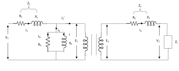
The basic transformer and its equivalent circuit both are shown below,
Fig. Equivalent Transformer Circuit
Iµ - magnetising component of current
Iw = working component
R0 – Non- inductive resistance
I0 – No load current
X0 = E1/I0. R0 = E1/Iw
E2/E1 = N2/N1 = K
E’2 = E2/K = E1
V’2 = V2/K
I’2 = K I2
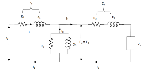
The total equivalent circuit is again given as,
But the above circuit is exact equivalent but harder to solve so, it can be further simplified as,
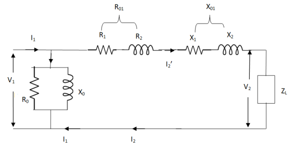
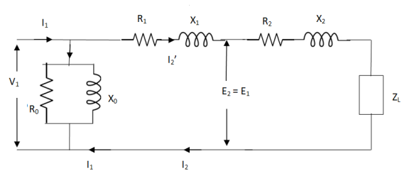
Z = Z1 + Zm || ( Z’2 + Z’L )
= Z1 + Zm(Z’2 + Z’L)/Zm + (Z’2 + Z’L)
Z’2 = R’2 + jX’2
Zm = impedance of exciting circuit
V1 = I1[ Z1 + Zm(Z’2 + Z’L) / Zm + (Z’2 + Z’L) ]
(1). Core or Iron Loss :
This includes both hysteresis loss and eddy current loss. Iron or core loss is found from open circuit test.
Hysteresis Loss(Wh) = nB1.6max f V Watt
Eddy current Loss(We) = P B2max f2 t2 Watt
(2). Copper Loss :
This is due to ohmic resistance of the transformer windings.
Total cu loss = I21 R1 + I22 R2
= I21 R01 + I22 R02
Cu loss α I2
The value of cu loss is found from short-circuit test.
Efficiency of transformer :
Basically efficiency is defined as
n = output/input
But for transformer there are small amount of losses so the improved way to find efficiency is
n = output/output + losses
n = output/output + cu loss + iron loss
Or n = Input – losses/Input
= 1 – Losses/Input
Condition for maximum efficiency :
For n to be maximum dn/dI1 = 0
(Ww) cu loss = I21 R01 or I22 R02
Iron loss = Hysteresis loss + Eddy current loss
= Wn + We = Wi
n = Input – losses/Input
Primary Input = V1I1 Cosφ1
n = V1 I1 Cosφ1 – losses/V1 I1 cos φ1
n = V1 I1 cos φ1 – I21 R01 – Wi / V1I1 cosφ1
= 1 – I1R01/V1cosφ1 – Wi/V1I1cosφ1
Differentiating w.r.t I1 both sides of above equation we have
Dn/dI1 = 0 – R01/V1cosφ1 + Wi/V1I21 Cosφ1
For max value dn/dI1 = 0
R01/V1cosφ1 = Wi/V1I21 cosφ1
Wi = I21 = I21 R01
Hence,
Wi = Wcu
Iron loss = copper loss
The value of output current for maximum efficiency will be
I2 = √Wi/R02
The maximum efficiency can also be given as,
nmax = full load x √ Iron loss / F.L .cu loss
Or
nmax = R’ x full load KVA x pf / R’ x full load KVA x pf + Wi + Wcu x 100
R’ = ratio of actual to full load KVA
Wi = iron loss (KW)
Wcu = copper loss (KW)
Q1). In a 50 KVA, 2200/200 V, 1-φ transformer, the iron and full-load copper losses are 400 W and 450 W respectively. Calculate n at unity power factor on (i). Full load (ii). Half-full load?
Sol. (i). Total loss = 400 + 450 = 850 W
F.L output at unity power factor = 50 x 1
= 50 KVA
n = 50 / 50 + .850 = 50/50.850 = 0.98 = 98%
(ii). Half full load, unity pf
= 50 KVA/2 = 25 KVA
Cu loss = 400 x (1/2)2 = 100 W
Iron loss is same = 450 W
Total loss = 100 + 450 = 550 W
n = 25/25 + 0.55 = 25/25.55 = 0.978 = 97.8 %
Q>. A 40 KVA 440/220 V, 1- φ, 50 Hz transformer has iron loss of 300 W. The cu loss is found to be 100 W when delivering half full-load current. Determine (i) n when delivering full load current at 0.8 lagging pf (ii) the percentage of full-load when the efficiency will be max.
Sol. Full load efficiency at 0.8 pf
= 40 x 0.8/(40 x 0.8) + losses
Full load cu loss = (440/220)2 x 100
= 400 W
Iron loss = 400 + 300
= 700 W
n = 40 x 0.8/(40 x 0.8) + 0.7 = 97.8 %
(ii). KVA for maximum / F.L KVA = √ iron loss / F.L cu loss
= √300/400 = 0.866
(1). Open circuit test
(2). Short circuit test
(1). OPEN CIRCUIT TEST :
Basically these tests are performed to find the basic parameters of transformers. The open circuit test is performed to determine no-load loss(core loss) and no-load current I0 which is helpful in finding X0 and R0.
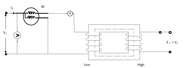
Fig. Open Circuit Test
In this test the high voltage winding is left open and the other is connected to supply.
A wattmeter W, voltmeter V and an Ammeter A are connected to L.V. Winding.
Due to applied voltage in primary, flux is set up in core, and hence normal iron loss occurs. This is recorded in Wattmeter. The current I0 is measured by Ammeter A.
Wattmeter reading represents core loss under no-load condition.
The wattmeter reading will be given as
W = V1 I0 cos φ0
Iµ = I0 Sin φ0
Iw = I0 cos φ0
X0 = V1/Iµ, R0 = V1/Iw
At no load I0 ≈ Iµ
I0 = V1 Y0
Y0 – Exciting Admittance
W = V21 G0
G0 – Exciting conductance
B0 = √ Y20 – G20
B0 – Exciting susceptance
(2). SHORT CIRCUIT TEST :
This test is used to determine
(i). Equivalent Impedance (Z01, Z02), leakage reactances (X01 or X02), Total resistance (R01, R02).
(ii). Cu losses are also calculated at full load.
(iii). The regulation of transformer can be determined as Z01, Z02 can be calculated.
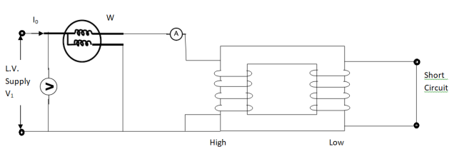
Here low voltage is short circuited. And the supply is through high voltage (primary here).
As applied voltage is small, hence the flux φ induced is also small.
As core losses are very small, the wattmeter reading is the cu-loss at full load for whole transformer.
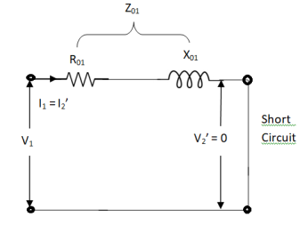
The equivalent circuit is shown below,
Z01 = Vsc/I1
Vsc = voltage to circulate rated load current
W = I21 R01
R01 = W / I21
X01 = √ Z201 – R201
R’2 = R01 – R1
Polarity test
The polarity test of a transformer can be done by measuring only voltage at no load. The basic connections are shown in below circuit.
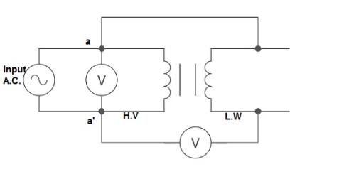
Fig: polarity Test
From above circuit input is applied for one winding. There is another voltage ‘V’ measured between one winding from each terminal. If voltage V’ > V, polarity is additive. If voltage V’ < V, polarity is subtractive.
Back to Back Test:
Sumpner's test or back to back test on transformer is another method for determining transformer efficiency, voltage regulation and heating under loaded conditions. Sumpner's test or back to back test is done with two identical transformers. Both transformers are connected to supply such that one transformer is loaded on another. Primaries of the two identical transformers are connected in parallel across a supply. Secondaries are connected in series such that emf's of them are opposite to each other. Another low voltage supply is connected in series with secondaries to get the readings, as shown in the circuit diagram shown below.
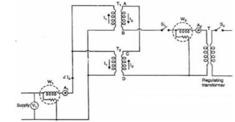
Fig: Back to Back Test
In above diagram, T1 and T2 are identical transformers. The secondaries are of opposite polarity the emf's cancel each other, as transformers are identical. In this case, as per superposition theorem, no current flows through secondary. The current drawn from V1 is 2I0, where I0 is equal to no load current of each transformer. Thus, input power measured by wattmeter W1 is equal to iron losses of both transformers. So, we can write
iron loss per transformer Pi = W1/2.
Now, a small voltage V2 is injected into secondary with the help of a low voltage transformer. The voltage V2 is adjusted so that, the rated current I2 flows through the secondary. In this case, both primaries and secondaries carry rated current. Thus, short circuit test is simulated and wattmeter W2 shows total full load copper losses of both transformers.
i.e. copper loss per transformer PCu = W2/2.
Q1>. The primary and secondary windings of a 30 KVA, 5000/330 V, 1- φ transformer having resistance of 15 Ω and 0.02 Ω. The reactance referred to primary is 34 Ω. Calculate primary voltage required to circulate full-load current when the secondary is S.C. Also calculate the pf?
Sol. K = 330/5000 = 33/500
X01 = 34 Ω
R01 = R1 + R2/K2 = 15 + 0.02(500/33)2 = 19.59 Ω
Z01 = √ R201 – X201
= √ 19.592 + 342
Z01 = 39.23 Ω
F. L I1 = 30,000/5000 = 6A
Vsc = I1 Z01 = 6 x 39.23 = 235.4 V
S.C. Power factor = R01 / Z01 = 19.59/39.23 = 0.5
Q.2). In no-load test of 1- φ transformer, the test data are
Primary voltage = 200 V,
Resistance of primary = 0.6 Ω
Secondary voltage = 100 V
Primary current = 0.6 A
Power input = 30 W
Find (a) Turns ratio (b) Magnetising component of no-load current (c) Working component (d) Iron loss
Sol>. (a). N1/N2 = 200/100 = 1
(b). W = V1 I0 cos φ0
Cos φ0 = 30/200 x 0.6 = 0.25, sin φ0 = 0.97
Iµ = I0 sin φ0 = 0.6 x 0.97 = 0.58 A
©. Iw = I0 Cos φ0 = 0.6 x 0.25 = 0.15 A
(d). Cu loss = I20 R1 = (0.6)2 x 0.6 = 0.216 W
Iron loss = 30 – 0.216 = 29.78 W
Q.3 Obtain the secondary voltage when delivered 10 KW at 0.8 PF.logging . The primary volt be 220v. The 300/600 v 50H2, 1- Transformer has following test results.
O.C test-:200v, 0.8A 70W-L.V side
S.C test-: 12V,10A 80W-HV side
Soln:- O.C TEST
W= COS
COS 
70=200*0.8*Cos
Cos = 0.436
Sin =0.899
 =
= COS
COS =0.8*0.436=0.35A
I =
= sin
sin = 0.8*0.899=0.72A
 =
= =
= =571.4
 =
= =
= =277.8𝛺
S.C TEST-:
 =
= =
= =1.2A
=1.2A
K= =2
=2
Z01= =
= =0.3
=0.3
I22 =W
=W
RO2= =0.7
=0.7
R01= =
= =0.175𝛺
X01=
= 
X01 = 0.244
Output KVA = =12.5
=12.5
I2= = 20.83A
Z02=1.2A R02=0.7𝛺
X02= =0.975𝛺
Total transformer drop refereed to secondary
= I2 (RO2COS + X02Sin
 )
)
= 20.83(0.7*0.8+0.975*0.6)
= 23.85v
 = 600 - 23.85=576.15v
The core loss of a transformer depends on the frequency and the maximum flux density when the volume and the thickness of the core laminations are known. The core loss comprises of two losses:
a) Hysteresis Loss Wh=P f
f
b) Eddy Current Loss We= Q f2 where Q is constant
Total core loss Wi= Wh+ We
= P f+ Q
f+ Q f2
f2
To find P and Q we need to carry out two different experiments at two different frequencies but with same maximum flux density. After having values of P and Q hysteresis and eddy current losses can easily be calculated.
As the supply is in 3-phase so we need this transformer. Its alternating voltage and currents differ in phase by 120 degrees.
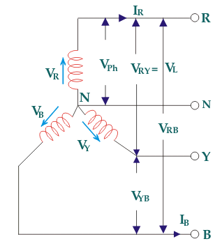
Fig: Three phase Transformer
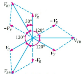
Fig: Line and phase voltage
Construction:
a) Core Type:
The construction of a core type three phase transformer is as shown in the figure. The core consists of three legs or limbs. The core is made up of thin laminated sheets to reduce eddy current losses. Each limb has primary and secondary windings in cylindrical shape (former wound) arranged concentrically. The construction is shown in the figure.
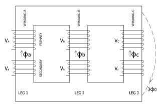
Fig: Core type 3-phase transformer
b) Shell Type:
In a shell type three phase transformer, three phases are more independent than they are in core type. Each phase has its individual magnetic circuit. The construction of shell type three phase transformer is illustrated in the figure at right. The construction is similar to that of three single phase shell type transformers kept on the top of each other.
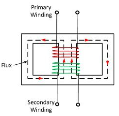
Fig: Shell Type 3-phase Transformer
Star – star or Y/Y connection: -
The below figure shows transformers connected in Y/Y on both primary and secondary sides. The ratio of line voltage and transformation ratio of line voltage and transformation ratio of both primary and secondary of each transformer in same. Hence the phase voltage VP =  . VLine (line voltage)
This connection works only if the load is balanced.
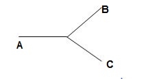
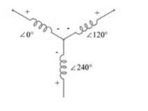
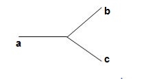
Fig: Three phase transformer Y-Y connection
- The effect of unbalanced load can be balanced by placing single load between a and n on secondary.
- Power to load is supplied by primary side A.
- As, A is in series with B and C and has b and c open on secondary, so it cannot supply required power.
- Now, B and C acts as high impedance in this condition, allowing very less flow of current in A.
- A low resistance can be connected between a and n which is approaching to short circuit. So, small current flows.
- Hence, EAN will reduce to zero but EBN and ECN will rise to full primary line voltage.
- The above shown connection is most economical for small, high-voltage transformers because the number of turns per phase and the amount of installation required is minimum.
- One more advantage is that the installation is stressed to the extent of line to neutral voltage i.e. 58% of line voltage.
- For having a sine wave voltage at output it is necessary that sine wave of flux should be in the core. To fulfil this we require third harmonic component of exciting current.
- To attain this if primary neutral is isolated then triple current cannot be attained. So, the best way is to provide a territory winding to each transformer of 1000 kVA rating.
Delta – Delta or Δ – Δ connection: -
- In this connection the ratio of transformation between both primary and secondary line voltage is same.
- There is no internal phase shift between phase and line voltages on either side as it was in Y-Y connection.
- The third harmonic component of current can flow in the Δ-connected transformer primaries.
- The balancing of load is easy unlike Y-Y connections.
- As the phases are 120˚ apart w.r.t. Third harmonic, the flux is sinusoidal which results in sinusoidal voltages.
- If anyone transformer becomes disabled. The system can continue to operate in open delta or V-V connection.
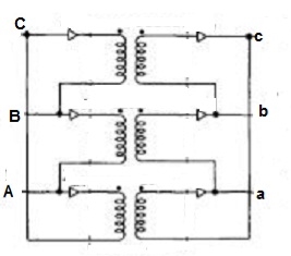
Fig: Δ-Δ connection
Wye / Delta or Y/Δ connections: -
- It is mainly used at the subtraction where the voltage is to be stopped down.
- Primary winding is Y connected and the ratio of secondary & primary line voltage is 1/
 .
. - There is 30˚Ø-shift between primary & secondary of line voltage.
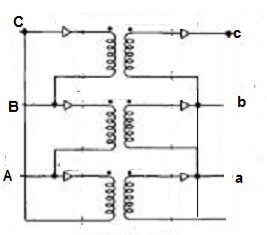
Fig: Y/Δ connection
Delta/Wye or Δ/Y connection:-
- It is used where we need to stop up the voltage.
- The primary and secondary line voltages and line currents are out of phase with each other by 30˚.
- The ratio of secondary to primary voltage is
 times of the transformation ratio of each transformer.
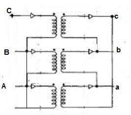
Fig: Δ-Y connection
Comparative features:
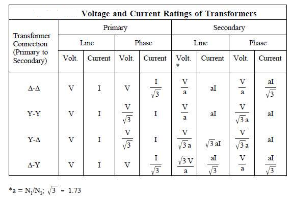
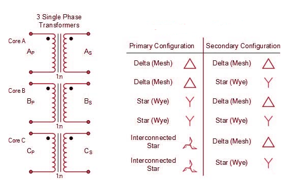
Que 1. A 3-Ø, 50Hz transformer has delta connected primary and star-connected secondary, the line voltage being 20,000 V and 500 V respectively. The secondary has a star connected balanced load at 0.8 lagging p.f. The line current of primary side is 5A. Determine the current in each coil of the primary and secondary line. Also find the output of the transformer?
→ Phase voltage on primary side = 20,000 V
Phase voltage on secondary =  V
V
K = 
Primary phase current = 
Secondary phase current = 
= 
= 200 A
Output =  VLILcosØ
= 
= 138.56 kW
Que 2. A 100 kVA, 3Ø, 50 Hz , 3500/500 V transformer is Δ – connected on the h. V side and Y-connected on the L.V. Side. The resistance of h.V. Winding is 3.5 Ω / phase and that of L.V is 0.02 Ω per phase. Calculate the iron losses of the transformer at normal voltage and frequency if its full load efficiently be 95.1 % at 0.8 p.f. ?
→ Full load output = 100 × 0.8 = 80 kW
Input =  kW
kW
Total loss = Input – Output
= 83.2 – 80
= 3200 kW
K = 
K = 
= 
RO2 = R2 + k2R1
= 
= 0.044 Ωs
Full-load secondary phase current I2
= 
= 115.4 A
Total Cu Loss = 3I22RO2
= 3 × 0.044 × (115.4)2
= 1760 W
Iron Loss = Total loss – Cu Loss
= 3200 – 1760
= 1440 W
Parallel operation of single phase transformer
If the present transformers are not capable of supplying any amount of additional load which is required, then the parallel connections are used to fulfil the requirement. The basic circuit for parallel transformer is shown below.
The condition required for parallel connections: -
- The primary windings of the transformer should be suitable for supply voltage and frequency.
- The connections w.r.t. Polarity of transformer should be proper.
- The voltage ratings of both primaries and secondaries should be identical.
- In order to avoid circulating current the ratio X/R and percentage impendences should be equal in magnitude.
- The transformer that have different KVA ratings should have equivalent impendences inversely proportional to individual KVA rating.
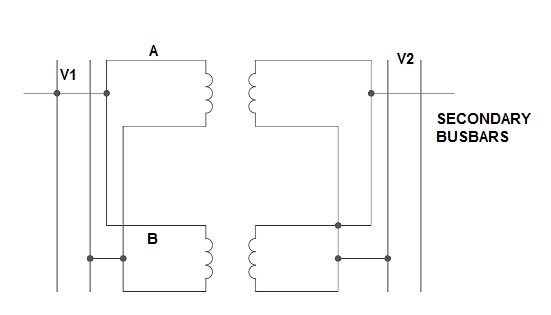
Fig. Parallel Connection of 1-ØTransformer
1) Ideal Case :-
Here both the transformers are considered to have same voltage ratio and impedance voltages triangles identical in size and shape.
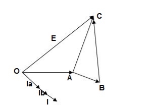
Fig. Phasor for ideal Case
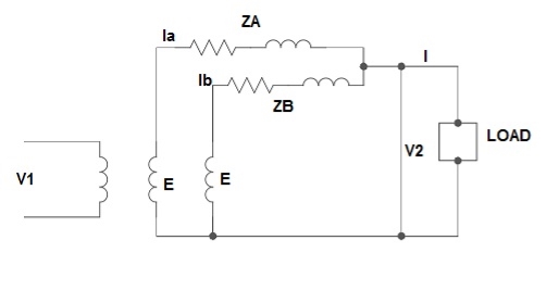
Fig: Ideal Case
I = IA + IB
V2 = E - IAZA
IAZA = IBZB
IA = 
IB = 
E – No load secondary voltage
V2 – Terminal voltage
IA , IB – Currents of each Transformer
2) Equal Voltage Ratio :-
Let No-load voltage of each secondary be same E = EA = EB. The change in the secondary is shown below.
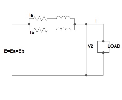
Fig: Equal Voltage Ratio
All values are considered referred to the secondary.
ZA , ZB = impedances of transformer
IA , IB = currents of transformer
V2 = common terminal voltage
IAZA = IBZB = IZAB
ZAB = ZA || ZB
ZA = IZABZA ,
IA = 
V2IA = 
V2IB = 
Let V2I × 10-3 = S (Combined Load KVA)
SA = 
SB = 
3) Unequal Voltage Ratios :-
Here the no load secondary voltages are unequal.
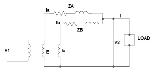
Fig.: Unequal Voltage Ratios
EA , EB = no-load secondary emp
Z1 = load impedance across secondary.
Here circulating current exist as the voltage are unequal (IC).
IC = 
EA = IAZA + V2
EB = IBZB + V2
V2 = IZL = (IA + IB)ZL -----------------(1)
EA = IAZA + (IA + IB)ZL -----------------(2)
EB = IBZB + (IA + IB)ZL -----------------(3)
EA – EB = IAZA – IBZB
IA = 
If ZA and ZB are smaller than ZL.
Substitute IA in equation (3) and solve
IA = 
IB = 
Neglecting ZA ZB in comparison with ZL(ZA + ZB)
We get above equations.
I = IA + IB
I = 
V2 = EA - IAZA and V2 = EB – IBZB
Parallel operation of 3-Ø Transformer
The conditions are same as in case of 1-Ø transformer.
- The voltage ratio must refer to the terminal voltage of primary and secondary.
- The phase displacement between primary and secondary voltages must be same for all transformers.
- The phase sequence must be same.
- All three transformers in 3-Ø transformer bank will be of same construction.
Que 1. What should be the kVA rating of each transformer in V-V bank when 3-Ø balanced load is 50 kVA. If a third transformer is connected for operation find % increase in rating?
→ kVA for each transformer has to be 15%
KVA per transformer = 
= 28.75
Δ-Δ bank rating = 28.75 × 3
= 86.75
Increase = 
= 72.5 %
Que 2. A balanced 3-Ø load of 120 kW at 1100V 0.866 lag p.f is supplied from 1500V , 3-Ø main through 1-Ø transformer connected – (i) Δ-Δ (ii) Y-Y
Find current in the windings of each transformer and p.F at which they operate in each case.
→ (i) Δ-Δ
 VLILcosØ = 120,000
 × 1100 × IL × 0.866 = 120,000
IL = 72.73 A
Secondary line current = 72.73 (= IL)
Secondary phase current =  = 41.99 A
K = 
Primary phase current =  = 20.99 A
(ii) Y-Y connection
 × 1100 × I × 0.866 = 120,000
I = 72.73 A
Secondary phase current = 72.73 A
Primary phase current =  = 41.99 A
Transformer p.f = 86.6 % of 0.866
= 0.75 (lag)
Que 3. Two transformers are required for a Scott connection operating from 410 V 3-Ø supply for supplying two 1-Ø furnaces at 200 V on the two-phase side. If total output is 130 kVA, calculate secondary to primary turn ratio and the winding of each transformer?
→ For main Transformer
Primary voltage = 410 V
Secondary voltage = 200 V

Secondary current =  = 325 A
Primary current = 325 × 
= 153.54 A
For teaser Transformer
Primary volts =  = 355 V
Secondary volts = 200 V

It is a transformer in which only one winding is common it both primary and secondary because it has one windy it uses loss copper and is cheaper.
It can be step -up and step down auto-transformer. The circuit for both is shown below.
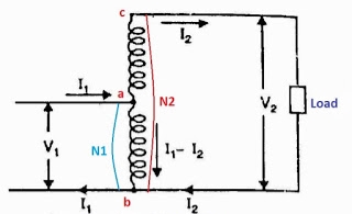
Fig a: Step up auto transformer
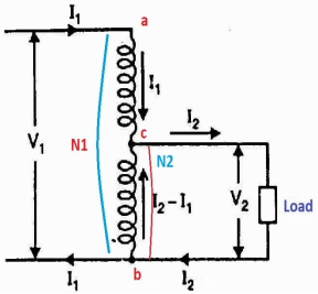
Fig b: Step Down Autotransformer
CB-Primary winding
BA- Secondary windings
Negating iron loss and no-load current-
 =
= =
= =K
=K
The current in AB( ) is vector difference (
 -
- )
)  >
>
An auto transformer when compared to as ordinary 2- winding transformer having same output, given higher efficiency and is smaller in size with superior voltage regulation.
FOR AUTO TRANSFORMER :-
From above fig (a)& (b)
Weight of copper in AC  (N1-N2)I1
Weight of copper in BA (N2(I2-I1)
Total weight of copper  (N1-N2) I1+N2(I2-I1)
  auto transformer
For 2- winding transformer:-
Weight of  on primary
  N1I1
N1I1
Weight of  on primary
  N2I2
N2I2
Total weight of  N1I1+N2I2

 =
=
=  = 1-
= 1- =1-k
=1-k
 = K ,
= K ,  =
=
Weight  in auto transformer =(1-k)*(weight of
  in ordinary transformer)
Saving = Wo-Wa
= W0-(1-k)W0
Saving = Kwo
Power transformer inductively =(1-k) input hence, saving will increase at K approaches unity.
Q. An auto transformer suppliers load of 4KW at 100v at unity pf. IF the applied primary voltage is 220v. Calculating power transferred to load (a) Inductively (b) conductively.
Soln, Power transferred inductively = Input(1-k)
Power transferred conductively = K* Input
K=  =
=
Input= Output =4KW
Inductively transferred power =4( )
)
=3.82KW
Conductively transferred power =  *4
*4
= 0.182 kw
Magnetizing current is the term used to denote the total current that flows into the primary of a transformer when the transformer is energized at a specific voltage and frequency, with the secondaries open circuited. Although known as magnetizing current it is actually the combination of the current required to magnetize the core (I1) and the current required to supply the losses in the core (I2).
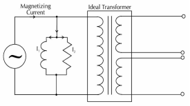
We know from Biot-Savart’s law that a current carrying conductor produces magnetic field. Magnetic field strength H is proportional to the current which produces the field. From Ampere’s Circuital law, it can be proved that H is proportional to current I. If a current carrying coil produces magnetic flux which traverses an average length of l in complete flux path, then
Hl = NI
In a magnetic circuit, this field is represented by magnetomotive force. It is analogous to the electromotive force in electrical circuit. This field is responsible to “set up” certain flux, which in turn gives rise to certain flux density B. Note that, here H is cause and B is its effect. The amount of flux which can be setup in a material is determined by an inherent property of the material, called as permeability, denoted by µ.
B = µH
When external magnetic field H is applied to a material, all the domains align in a particular direction, setting up net flux in the material. Due to domain alignment B (i.e. the magnitude of B) increases. However, after a certain value of B, the slope of B − H curve starts reducing as shown in Figure below
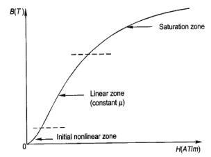
Fig: Magnetization curve
B-H Curve:
We cannot measure B and H directly. Further if we have transformer, we only have terminal measurements are with us. Hence, it is required to process the signals to get values of B and H. From Faraday’s law, V = N dφ/dt . Also, B is directly proportional to flux φ.
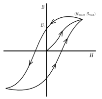
Fig: B-H curve
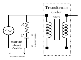
Fig: Circuit for B-H curve
Harmonics in transformers cause an increase in the iron and copper losses. Voltage distortion increase losses due to hysteresis and eddy currents and causes overstressing of the insulation material used. The primary effect of power line harmonics in transformer is, thus the additional heat generated. Other problems include possible resonance between the transformer inductance and the system capacitance, thermal fatigue due to temperature cycling and possible core vibrations.
Scott connection or T-T connection
For making 3-Ø to 3-Ø transformation from two transformers we use this connection.
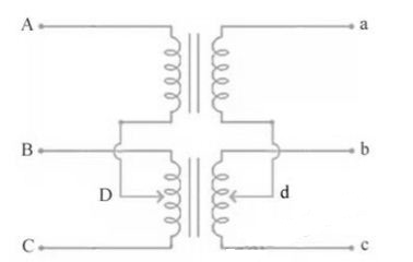
Fig. : Scott Connection
- The above figure shows that the centres of one transformer are tap, and has 0.866 tap and is known as Leaser Transformer.
- One ends of both the primary and secondary of Leaser transformer are joined to centre tap on both primary and secondary of main transformer.
- There is one transformer having its centre taps on both primary and secondary and is known as main transformer.
The voltage diagram is shown below
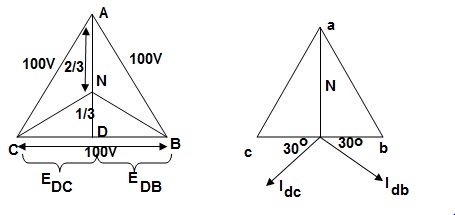
Fig. : Voltage and Phase diagram
- EDC and EDB are each 50 V and 180˚ out of phase because coils DB & DC are on same circuit but in opposition.
- EDA is equal to 86.6 V
 and lags behind the voltage across main by 90˚.
 - Idb lags behind voltage Edb by 30˚ and Idc leads Edc by 30˚.
- The teaser transformer and each half of the main transformer all operate at different power factors.
- Full rating of transformer is not utilized. The teaser transformer operate at 0.866 of its rated value and main transformer coil operates at cos 30˚ = 0.866 p.f
Three to six phase conversion:
A greater number of phases results in the reduction of harmonics in the alternating current. Therefore, 6-phase is preferred to 3-phase for rectification. There are several methods of connecting transformers for obtaining 3-to-6-phase transformation. A simple arrangement known as the 6-phase star connection is shown in Fig.
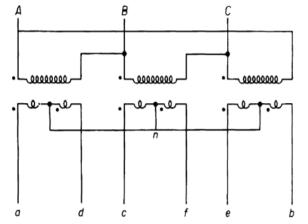
Fig: 3-phase delta to six phase star connection

Fig: Phasor of primary and secondary voltages
The secondaries are provided with centre taps, which are connected together to form the neutral of the 6-phase side. The primaries are shown connected in delta but they may also be connected in wye. The 6-phase forked-wye or double-zigzag connection is shown in Figure below. In this arrangement, each secondary winding is divided into three equal parts and the portions that are shown parallel to each other. A 6-phase transformation may be affected by means of three single-phase transformers.
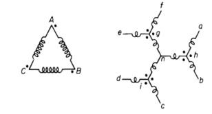
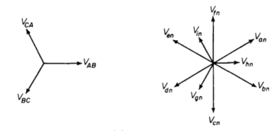
Fig: Six phased forked-wye connection
On-Load Tap changing:
For uninterrupted supply we use on-load tap changing transformer. Such a transformer is known as a tap-changing under load transformer. While tapping, two essential conditions are to be fulfilled.
- The load circuit should not be broken to avoid arcing and prevent the damage of contacts.
- No parts of the windings should be short–circuited while adjusting the tap.
The tap changing employing a centre tapped reactor R show in the figure.
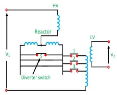
Fig: On load Tap changing
Here S is the diverter switch, and 1, 2, 3 are selector switch. The transformer is in operation with switches 1 and S closed. To change to tap 2, switch S is opened, and 2 is closed. Switch 1 is then opened, and S closed to complete the tap change. It is to be noted that the diverter switch operates on load, and no current flows in the selector switches during tap changing. It is to be noted that the diverter switch operates on load, and no current flows in the selector switches during tap changing. During the tap change, only half of the reactance which limits the current is connected in the circuit.
No-Load Tap Changing:
The cheapest method of changing the turn ratio of a transformer is the use of Off Load Tap Changer. As the name indicates, it is required to deenergize the transformer before changing the tap. A simple Off Load Tap Changer is shown in Figure below
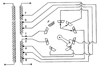
Fig: No-Load Tap Changing
It has eight studs marked one to eight. The winding is tapped at eight points. The face plate carrying the suitable studs can be mounted at a convenient place on the transformer such as upper yoke or located near the tapped positions on the windings. The movable contact arm A may be rotated by handwheel mounted externally on the tank.
If the winding is tapped at 2% intervals, then as the rotatable arm A is moved over to studs 1, 2; 2, 3; . . . 6, 7; 7, 8 the winding in circuit reduces progressively by it from 100% with arm at studs (1, 2) to 88% at studs (7, 8). The stop F which fixes the final position of the arm A prevents further anticlockwise rotation so that stud 1 and 8 cannot be bridged by the arm.
As the name suggests this transformer can be made by adding one additional winding. The main use of this type of transformer is for interconnections with the transmission line at various voltages, for measuring voltages of an H.V side transformer, synchronous condensers can be connected to this winding to inject reactive power in system for voltage control. Below is shown the figure which explains how the tertiary winding can be used for stabilization.

Figure: Tertiary winding for stabilization
The unbalanced load cab be divided into three phase sets i.e. positive, negative and zero sequence component. The star-star connection unbalanced load provides high reactance between line and neutral. The zero-sequence current component on secondary side cannot be balanced by primary current and hence magnetic flux is developed on the secondary side. Then the delta connected tertiary allows the circulation of zero-sequence current in it, as shown in the above figure. The equivalent circuit of the three winding transformer is shown below. There are three terminals primary (1), secondary (2), and tertiary (3) and one common terminal, neglecting the exciting current.
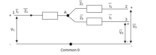
Figure: Single phase equivalent circuit of three winding transformer
The impedance can be calculated by the short circuit test. If  is the short circuit impedance of winding 1 and 2 with winding 3 open, then we can write
 =
=  +
+


The above three equations can also be written as


The core loss, magnetizing loss and turn ratio can be determined by open circuit test on any one of the three windings.
The main source of heat generation in transformer is its copper loss or I2R loss. If this heat is not dissipated properly, the temperature of the transformer will rise continually which may cause damages in paper insulation and liquid insulation medium of transformer. So, it is essential to control the temperature with in permissible limit to ensure the long life of transformer by reducing thermal degradation of its insulation system.
1) ONAN (Oil Natural Air Natural):
This is the simplest transformer cooling system. In this the natural convectional flow of hot oil is utilized for cooling. In convectional circulation of oil, the hot oil flows to the upper portion of the transformer tank and the vacant place is occupied by cold oil. This hot oil which comes to upper side, will dissipate heat in the atmosphere by natural conduction, convection and radiation in air and will become cold. In this way the oil in the transformer tank continually circulate when the transformer put into load.
As the rate of dissipation of heat in air depends upon dissipating surface of the oil tank, it is essential to increase the effective surface area of the tank. So additional dissipating surface in the form of tubes or radiators connected to the transformer tank. This is known as radiator bank of transformer.
2) ONAF(Oil Natural Air Forced):
The Heat dissipation can be increased, if dissipating surface is increased but it can be made further faster by applying forced air flow on that dissipating surface. Fans blowing air on cooling surface is employed. Forced air takes away the heat from the surface of radiator and provides better cooling than natural air. As the heat dissipation rate is faster and more in ONAF transformer cooling method than ONAN cooling system.
3) OFAF(Oil Forced Air Natural):
In OFAF cooling system the oil is forced to circulate within the closed loop of transformer tank by means of oil pumps. The main advantage of this system is that it is compact system and for same cooling capacity OFAF occupies much less space than farmer two systems of transformer cooling. Actually in oil natural cooling system, the heat comes out from conducting part of the transformer is displaced from its position, in slower rate due to convectional flow of oil but in forced oil cooling system the heat is displaced from its origin as soon as it comes out in the oil, hence rate of cooling becomes faster.
4) OFWF(Oil Forced Water Forced):
In OFWF cooling system of transformer, the hot oil is sent to water heat exchanger by means of oil pump and there the oil is cooled by applying sowers of cold water on the heat exchanger’s oil pipes.
5) ODAF(Oil Directed Air Forced):
The forced circulation of oil directed to flow through predetermined paths in transformer winding. The cool oil entering the transformer tank from cooler or radiator is passed through the winding where gaps for oil flow or pre-decided oil flowing paths between insulated conductor are provided for ensuring faster rate of heat transfer. This cooling method is generally used in very high rating transformer.
6) ODWF(Oil Directed Water Forced):
This is just like ODAF only difference is that here the hot oil is cooled in cooler by means of forced water instead of air. Both of these transformer cooling methods are called forced directed oil cooling of transformer.