UNIT 5
FREE BODY DIAGRAM
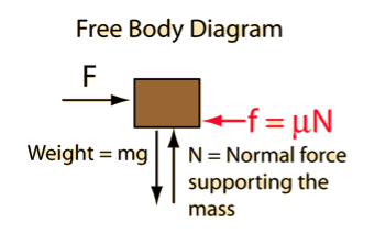
A free-body diagram is a sketch of an object of interest with all the surrounding objects stripped away and all of the forces acting on the body shown. The drawing of a free-body diagram is an important step in the solving of mechanics problems since it helps to visualize all the forces acting on a single object. The net external force acting on the object must be obtained in order to apply Newton's Second Law to the motion of the object.
A free-body diagram or isolated-body diagram is useful in problems involving equilibrium of forces. Free-body diagrams are useful for setting up standard mechanics problems.

Process to Draw a Free-Body Diagram
To construct a free body diagram, the following three steps are necessary.
- Draw Outlined Shape.
Imagine that the particle is to be isolated from its environments by drawing its outlined shape.
b. Show All the forces.
Then on this sketch, show all the types of forces. Identify Each Force that are known and unknown and display them.
c. Identify each force
Known forces are displayed with magnitude and direction. Letters are used to represent the magnitudes and directions of forces that are unknown.
For understanding the free-body diagram, we will consider the following example:

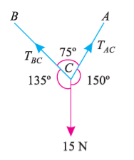
Suppose, in this example there are two strings (AC and BC) attached to an object at point C. Thus, the first step involves drawing a simple diagram representing the outline of all components.
Then, we need to show all the forces that are contributing in the given diagram. Here, there is 15 N force acting at point C, and there is tension in strings BC and AC due to 15 N force acting at C. Thus, identifying and displaying these forces onto the outline diagram is the second step.
The third step is finding the magnitude and direction of the forces and displaying them on the outline diagram. Using these steps, we can draw the free-body diagram as shown below.

Types of Support
- Roller Support: -
 Roller support is show in two ways as shown:
 A free body diagram of roller support is shown in figure given below
- Roller support offers only one reaction; which is always perpendicular to the base or plane of roller.
- All the steel trusses of the bridges have one of their ends supported on roller.
- Main advantages of the support are that beam can easily move towards left or right due to expansion & contraction.
2. Hinge support

- In this case, end of the beam is hinged to the support as shown in figure above.
- This type of support offers two reactions, one is parallel to base and perpendicular to the base
- All the steel trusses of the bridges have one of their end roller supported & other end is hinged
- Main advantage of this support is that beam remains stable.
- If both ends of the beam are roller supported, then beam can not be stable. Thus, one support of beam is made roller supported and other is hinged.
3. Internal Hinge: -
 When two members are connected by the hinge then this type of support is called as internal Hinge.


Internal Hinge
Reactions at internal Hinge
4. Fixed support: -
Fixed support offers three reactions as shown in figure below.
- Reaction in horizontal direction.
- Reaction in vertical direction.
- Moment (fixing moment)

Fixed Support
Kinematic Joints
Kinematic joints (or simply joints) are critical parts of a mechanism. The resultant motion in operating a mechanism is largely determined by the kinematic joints connecting the members of the mechanism. The kinematic joints allow motion in some directions and constrain it in others. The types of motion allowed and constrained are related to the characteristics and intended use of the joint, which can be usually characterized by the degrees of freedom it allows.
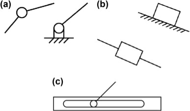
For a planar mechanism, there are two kinds of joints: planar J1 joints that allow one DOF (restrict two DOF); and planar J2 joints that allow two DOF (restrict one DOF). The revolute and slider joints discussed before are J1 joints and the pin-in-slot is a J2 joint, as shown in Figure 8.9. Three-dimensional or spatial joints are classified into two categories based on the type of contact between the two members making a joint: lower pair joint and higher pair joint. The contact can be point, line, or area. A third category of kinematic joint comprises the joints formed by combining two or lower pair and/or higher pair joints. Such joints are termed compound joints.

Figure 1.Planar joints.
(a) J 1: revolute/hinge/pin joint, (b) J1: prismatic/slider, and (c) J2: pin-in-slot.
The two members forming a lower pair joint have area contact between the two mating surfaces. The contact stress is thus smaller for lower pair joints as compared to higher pair joints. Lower pair joints have a long service life because the wear and stress are spread over a larger surface area of contact, and they allow better lubrication. The degrees of freedom for a lower pair joint are usually fewer, as the requirement for area contact between the members constrains the joint geometry.
Some of the lower pair joints we commonly see in mechanical systems are shown in Figure 4.9. Different joints allow different kinds of motion. For example, a revolute (or hinge or pin) joint allows the rotation of one rigid body with respect to another rigid body about a common axis. Therefore, a revolute joint eliminates a total of five DOF: three translational and two rotational.
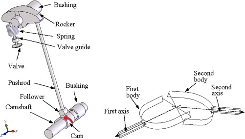
The contact between the two members of a higher pair joint has point or line geometry. The contact stress for a higher pair joint is large because the contact area is very small. If there is pure rolling contact between the members, then there is no relative sliding between the contact surfaces and thus friction and wear are minimal. The number of degrees of freedom for a higher pair joint can be large as the point or line contact allows for less constrained motion of members. A cam-follower, as shown in Figure 8.10, is a good example of higher pair joints, where a line contact is observed between the cam and the follower. A cam-follower allows two DOF, one rotational and one translational, along the center axes of the cam and the followers that are in parallel.

Figure 2. Higher pair joint: a cam-follower in the mechanism of an engine inlet or outlet valve.
Lower pair and/or higher pair joints are combined as per the design requirement to obtain compound joints. Compound joints composed of higher pair joints can be kinematically equivalent to lower pair joints and vice versa. By such combinations desirable features from the combining joints are retained to achieve robust joints.
A good example of a composite joint is a ball or roller bearing. The actual members in contact are balls or rollers with the inner and outer face. This is a rolling contact, which is a higher pair. However, the overall joint has the motion geometry of a revolute joint, a lower pair. A ball bearing has the low friction properties of rolling contacts and the high load capacity of revolute joints. Ball or roller bearings are kinematically equivalent to simple revolute joints. Another example is the universal joint shown in Figure 4.9(f). This is a combination of revolute joints and has two rotational degrees of freedom.
Kinematic Constraints
Two or more rigid bodies in space are collectively called a rigid body system. We can hinder the motion of these independent rigid bodies with kinematic constraints. Kinematic constraints are constraints between rigid bodies that result in the decrease of the degrees of freedom of rigid body system.
The term kinematic pairs actually refers to kinematic constraints between rigid bodies. The kinematic pairs are divided into lower pairs and higher pairs, depending on how the two bodies are in contact.
Lower Pairs in Planar Mechanisms
There are two kinds of lower pairs in planar mechanisms: revolute pairs and prismatic pairs.
A rigid body in a plane has only three independent motions -- two translational and one rotary -- so introducing either a revolute pair or a prismatic pair between two rigid bodies removes two degrees of freedom.

Figure A planar revolute pair (R-pair)

Figure A planar prismatic pair (P-pair)
Lower Pairs in Spatial Mechanisms
There are six kinds of lower pairs under the category of spatial mechanisms. The types are: spherical pair, plane pair, cylindrical pair, revolute pair, prismatic pair, and screw pair.

Figure A spherical pair (S-pair)
A spherical pair keeps two spherical centers together. Two rigid bodies connected by this constraint will be able to rotate relatively around x, y and z axes, but there will be no relative translation along any of these axes. Therefore, a spherical pair removes three degrees of freedom in spatial mechanism. DOF = 3.

Figure A planar pair (E-pair)
A plane pair keeps the surfaces of two rigid bodies together. To visualize this, imagine a book lying on a table where is can move in any direction except off the table. Two rigid bodies connected by this kind of pair will have two independent translational motions in the plane, and a rotary motion around the axis that is perpendicular to the plane. Therefore, a plane pair removes three degrees of freedom in spatial mechanism. In our example, the book would not be able to raise off the table or to rotate into the table. DOF = 3.

Figure A cylindrical pair (C-pair)
A cylindrical pair keeps two axes of two rigid bodies aligned. Two rigid bodies that are part of this kind of system will have an independent translational motion along the axis and a relative rotary motion around the axis. Therefore, a cylindrical pair removes four degrees of freedom from spatial mechanism. DOF = 2.

Figure A revolute pair (R-pair)
A revolute pair keeps the axes of two rigid bodies together. Two rigid bodies constrained by a revolute pair have an independent rotary motion around their common axis. Therefore, a revolute pair removes five degrees of freedom in spatial mechanism. DOF = 1.

Figure A prismatic pair (P-pair)
A prismatic pair keeps two axes of two rigid bodies align and allow no relative rotation. Two rigid bodies constrained by this kind of constraint will be able to have an independent translational motion along the axis. Therefore, a prismatic pair removes five degrees of freedom in spatial mechanism. DOF = 1.

The screw pair keeps two axes of two rigid bodies aligned and allows a relative screw motion. Two rigid bodies constrained by a screw pair a motion which is a composition of a translational motion along the axis and a corresponding rotary motion around the axis. Therefore, a screw pair removes five degrees of freedom in spatial mechanism.