Unit - 1
Introduction to Signals and Systems
With the advancement in technology there seems to be an improvement in the field of information sources such as audio(speech , acoustics , music and so on), image(video, multimedia, medical scans), medical signals(heart rate, blood pressure ,brain activity) and remote sensing data(geophysical,radar,sonar).
Some of the examples of system that manipulate signals are speech recognition, video streaming, cellular networks, and medical scans. The disciplines of signal and image processing are concerned with the analysis and synthesis of signals and their interactions with systems.
In communications the objective is to transfer information from one or many sources to one or many destinations which require design of transmission schemes. In mathematical tool it is used for analysis of deterministic and random signals and application to digital signal processing, digital image processing and digital/analog communications.
Key Take Aways:
Signals and Systems finds its application from basic to advancement technology.
Signal Properties
1.1.1 Periodicity
The signal’s behaviour/graph repeats after every T. Therefore,
x(t) = x (t + nT) or
x(t) = x (t – nT)
where, T is the fundamental period. So we can say that the signal remains unchanged when shifted by multiples of T.
Find the fundamental period T of the following continuous time signals
x(t) = sin 50 π t where Ωo = 50 π.
Time period T = 2 π/ Ωo = 2 π/50 π = 1/25. Sec
2. x(t) = 20 cos (10 πt + π/6) Ωo = 10 π
T = 2π/ Ωo = 2π/10 π = 1/5 sec.
Check whether the following signals are periodic or not
x(t) = 2 cos (10t+1) – sin(4t-1)
Time period 2 cos (10t+1) is T1 = 2 π/10 = π/5
Sin(4t-1) T2 = 2π/4 = π/2
T1/T2 = π/5/ π/2 = 2/5.
Since it is rational number the signal is periodic with period T = 2T2 =5 T1
= π sec.
x(t) = sin2t
= 1-cos2t
2
Period of the signal is T = 2 π/ Ω0 = 2 π/ 2= π
Signal is periodic.
x(t) = ej2 π/3n + ej 3 π/4n
Time period for ej2 π/3n
N1 = (2 π/ (2 π/3)) = 3m Here m=1 N1=3
Time period for ej 3 π/4n
N2 = (2 π/ (3 π/4)) = 8/3m here m=3 N2=8
N1/N2 = 3/8
8 N1 = 3 N2
N = 8N1=3N2 = 24.
N=24.
1.1.2 Absolute Integrability
Absolute integrable term refers to a function of a continuous variable.
Let us consider continuous time signals. We take a signal x (t), then take its absolute value and integrate it with respect to 't’. The limits of integration should be all possible values of 't'. In this case time 't' is a real variable. We plot the graph of 't' from -infinity to +infinity, that is entire time span possible.
Suppose we have a strictly time limited signal that is a rectangular pulse, so obviously this curve has a finite area under it. Therefore, we can say this signal is absolutely integrable.
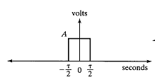
Figure 1. Band limited signal
1.1.3 Determinism and Stochastic character
Deterministic
A signal is said to be deterministic if there is no uncertainty with respect to its value at any instant of time or the signals which can be defined exactly by a mathematical formula are known as deterministic signals.
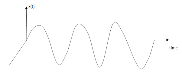
Figure2. Deterministic signal
Random
A signal is said to be non-deterministic(stochastic) if there is uncertainty with respect to its value at some instant of time. Non-deterministic signals are random in nature hence they are called random signals. Random signals cannot be described by a mathematical equation. They are modelled in probabilistic terms.

Figure 3. Random signal
Key Take Away
A periodic signal is one that repeats the sequence of values exactly after a fixed length of time, known as the period.
1.2.1 Unit Step
Unit step sequence:
The unit step sequence is defined as:
u(n) = 1 for n 
=0 for n<0
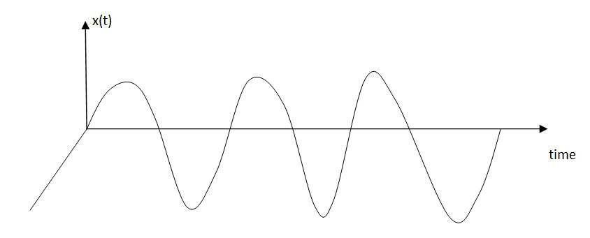
Figure 4. Unit Step Signal
1.2.2 Unit Impulse
The impulse function occupies an important place in signal analysis. It is defined as
 dt =1
dt =1
and
δ(t) =0 for t
The impulse function has zero amplitude everywhere except at t=0. At t=0 the amplitude is infinity such that the area under the curve is equal to one. The unit impulse function can be obtained by using limiting process on the rectangular pulse as shown in figure.
Note that the area under the rectangular pulse is equal to unity.

Figure 5. Impulse function
The rectangular pulse function of the figure can be expressed as
x(t) = 1/ ∆ [ u(t) – u(t-∆)] …………………………………. (1)
The impulse function can be obtained when the width ∆ ->0 that is
δ(t) = limp ∆-> 0 x(t)
= limp ∆-> 0 1/ ∆ [ u(t) – u(t-∆)]
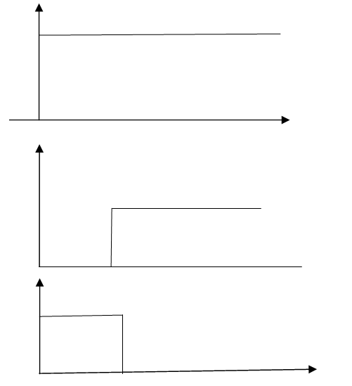
Figure6. Unit impulse with delay function
The delayed unit impulse function is defined as
 =1 for t=a
and  =0 for t
 a
a

Figure 7. Impulse function
1.2.3 Sinusoid
The discrete time sinusoidal signal is given by
x(n)= A cos (won + ɸ) ---------------------------(1)
where wo is the frequency and ɸ is the phase
Using Euler’s identity, we can write
A cos (won + ɸ) = A/2 e jɸ . e j won + A/2 e-jɸ e -jwon ---------------------(2)
Since | e jwon | 2 =1
The energy of the signal is infinite and the average power of the signal is 1.
An example of discrete time sinusoidal signal is shown in figure.

Figure 8. Sinusoidal sequence
1.2.4 Complex Exponential
The discrete time complex exponential signal is given by
x(n) = a n e j (won + ɸ) ------------------------------------(1)
= a n cos (wo + ɸ) + j a n sin (won + ɸ).
For |a| =1 the real and imaginary parts of complex exponential sequence are sinusoidal.
For |a| < 1 the amplitude of sinusoidal sequence decays exponentially
For |a| > 1 the amplitude of the sinusoidal sequences increases exponentially. Examples of these signals are given in figure.
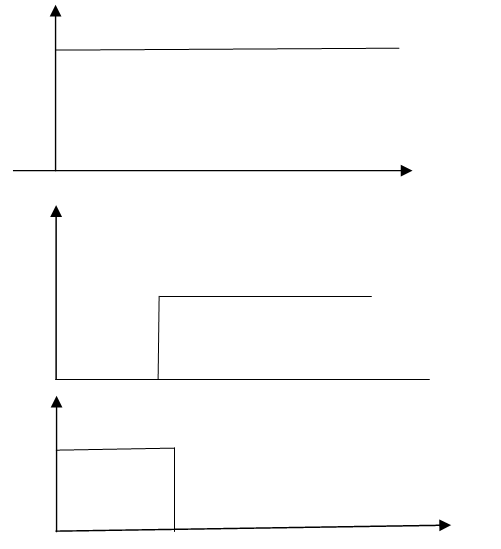
Figure 9. Complex exponential sequence
Key Take Always:
A signal is a way of conveying information
1.3.1 Continuous and Discrete time signal
A continuous time system is one which operates on the continuous time input signal and produces a continuous-time output signal.
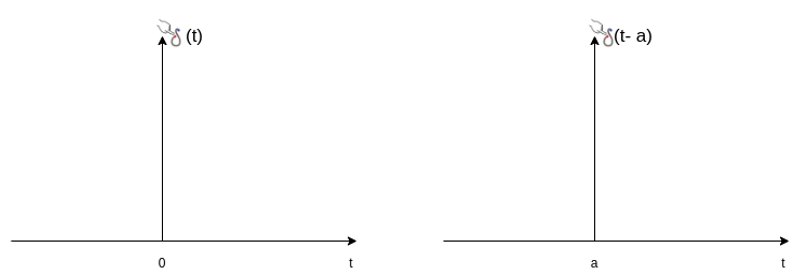
Figure 10. I/O of continuous time signal
If the input is x(t) and output is y(t) then
y(t) = T{x(t)}
That is x (t) is transformed to y(t).
Example: Amplifiers, filters, motors etc
Discrete time system is one which operates on discrete time input signal and produces a discrete-time output signal.
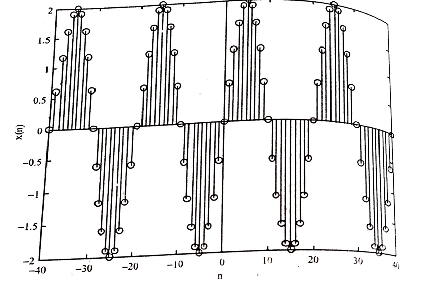
Figure 11. I/O of Discrete time signal
If the input is x(n) and output y(n) then
y(n) = T[x(n)]
1.2.5 Continuous and Discrete amplitude signals
Continuous-time discrete amplitude signals are basically digital signals.
Discrete amplitude is one which we get through quantization process and it depends how many levels of quantization one wants. In simple words, quantization means assigning the amplitude values of any analog signal to certain discrete levels, equidistant of each other based on certain criteria.
A square wave is a continuous-time discrete amplitude signal. For binary signals, there are only two quantization levels (0,1).
Some examples of continuous-time discrete amplitude signals:


Figure 12. Continuous and Discrete Amplitude Signals
Key Take Always:
Quantization means assigning the amplitude values of any analog signal to certain discrete levels
1.4.1 Linearity
Constitutes two properties:
Additivity/ Super position
If x1(t) -> y1(t)
and x2(t) -> y2(t)
then
x1(t) + x2(t) -> y1(t) + y2(t)
Property of scaling
if x1(t) -> y1(t)
a * x1(t) -> a * y1(t)
If both are satisfied, then system is linear
y(t) = x2(t)
The responses due to inputs x1(t) and x2(t) are given by
y1(t) = x1 2(t)
y2(t) = x2 2(t)
The output due to weighted sum of inputs is
y3(t) = T[ax1(t) + bx2(t)] = [ax1(t) + bx2(t)]2
The weighted sum of inputs
a y1(t) + by2(t) = ax12(t) + b x2 2(t)
y3(t) ≠ ay1(t) + by2(t)
System is non-linear.
1.2.6 Additivity and Homogeneity
Homogeneity
Homogeneity means change in input signals amplitude results in a corresponding change in the output signal’s amplitude.
That is a change in x[n] will result in a change in y [n]
Also, a change in k x[n] will result in a change in k y[n]
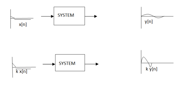
Figure13. Homogeneity
Additivity
Consider a system where input x1[n] produces an output y1[n]. Similarly, x2[n] produces y2[n].
The system is additive when
x1[n] + x2[n] = y1[n] + y2[n]
In other words, signals added at the input will produce signals added at the output.
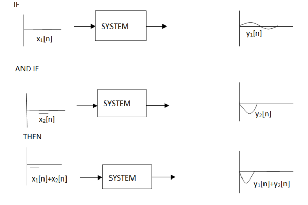
Figure14. Additivity
1.2.7 Shift Invariance
Shift invariance means that a shift in the input signal will result in an identical shift in the output signal
If x[n] -> y[n]
Then x[n’s] ->y [n +s] for any constant s
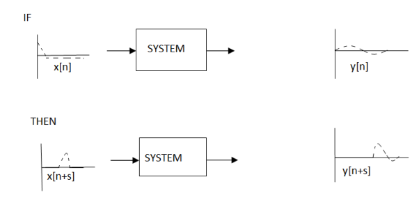
Figure.15 Shift Invariance
1.2.8 Causality
Examples of casual system:
y(t) = x(t) + x(t-1)
y(n) = n x(n) + x(n-3)
Examples of non-casual system
y(t) = x(t+3) + x 2 (t)
y(n) = x(2n)
For example
y(t) = 2 x(t) + 3 x(t-3)
let t=1 therefore y (1) = 2 x (1) + 3 x (-2)
The system output only depends upon present and past inputs. Hence, the system is causal.
y(t) = 2 x(t) + 3 x (t – 3) + 6 x(t+3)
let t=1 the system output is
y (1) = 2x (1) + 3 x (-2) + 6 x (4)
Here the output depends future input. Hence non –casual.
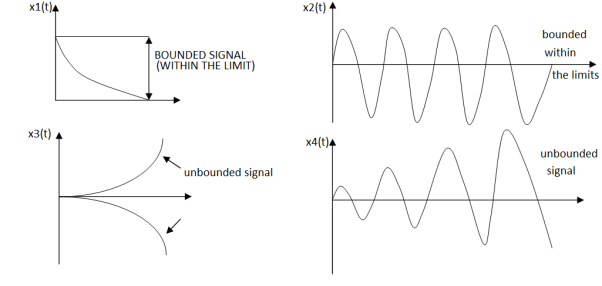
Figure 16. Stability of the system
An input signal x(t) is said to be bounded if it satisfies the condition |x(t) |≤Mx < ∞ for all t.
Similarly, the output signal is bounded if it satisfies the condition |y(t)| ≤My < ∞
The example for bounded and unbounded signals is as shown in the figure.
Note: For a bounded signal, the amplitude is finite.
Example 1: y (t) = x2(t)
Let the input is u(t) that is unit step then output y(t) = u2(t) = u(t) = bounded output.
Hence, the system is stable.
Example 2: y (t) = ∫x(t)dt∫x(t)dt
Let the input be u (t) then
output y(t) = ∫u(t)dt but ∫ u(t)dt = ramp signal
It is unbounded because the amplitude of ramp is not finite and tends to become infinite when t →infinite
Hence, the system is unstable.
1.2.10 Realizability
y(t)=x(t−1)y(t)=x(t−1) is a causal system, because its output is a time-delayed version of the original signal.
On the other hand, the second system y(t)=x(t+1)y(t)=x(t+1), is non-causal.
This system returns a time-advanced version of the input signal. This means, that for example at the output time t=0, the system requires access to the value of the input signal at time t=1. Clearly, this is impossible in a realizable system, as nobody can predict the future.
Key Take Aways:
A system that is linear and time-invariant. BIBO stability- The bounded input bounded output stability. Causality- Causal signals are signals that are zero for all negative time.
References:
1 Signals and Systems by Simon Haykin
2 Signals and Systems by Ganesh Rao
3 Signals and Systems by P. Ramesh Babu
4 Signals and Systems by Chitode