Unit – 1
Performance of Transmission Line
Pre-requisite
Transmission lines less than 80 km long and short lines. Medium length lines are roughly between 80 km and 240 km long. Lines longer than 240 km requires calculations in terms of distributed constants if a high degree of accuracy is required, although for some purposes a lumped parameter representation can be used for lines up to 320 km long.
A transmission line on a per phase basis can be regarded as a two ports network wherein the sending end voltage Vs and current Isare related to the receiving end voltage VRand current IR through ABCD constants.
 where AD – BC = 1
These constants can be determined easily for short and medium length lines by suitable approx., lumping the line impedance and shunt admittance. For long lines exact analysis has to be carried out by considering the distribution of resistance, inductance and capacitance parameters and the ABCD constants of the line are determined there from.
Following nomenclature has been adopted:
z= Series impedance / unit length / phase
y = shunt admittance / unit length / phase
r = resistance / unit length / phase
L = inductance / unit length / phase
C = capacitance / unit length / Phase to neutral
l = transmission line length
Z = zl = total series impedance / phase
Y = yl = total shunt admittance / Phase to neutral
Subscript S stands for sending end, R stand for receiving end quantity.
1) Short Transmission Line
The equivalent circuit of a transmission line is as shown:
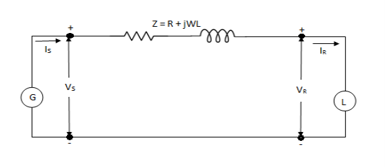
IS = IR
The voltage at the sending end is
VS = VR + IRZ
Where Z is zl, the total series impedance of the line.
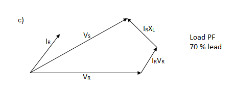
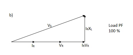
The effect of the variation of the power factor of the load on the voltage regulation of a line is mosteasily understood for the short line.
Voltage regulation of a transmission line is the rise in voltage at the receiving end, expressed in percent of full load voltage when full load at a specified power factor is removed while the sending end voltage is held constant.
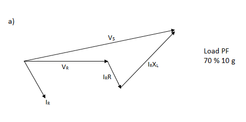
Percent Regulation =
2) The medium length line
The shunt admittance, usually pure capacitance is included in the calculations for a line of medium length.
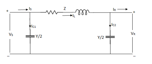
If the total shunt admittance of the line is divided into two parts at the sending and receiving ends of the line, the circuit is called a nominal π.


Substituting 1 in 2,


These ABCD constants are sometimes called the generalized circuit constants of the transmission line. In general, they are complex numbers.
A and D are dimensionless and equal to each other if the line is the same when viewed from either end. The dimensions of B and C are ohms and mhos respectively.
Nominal T- method
In this method, the capacitance of each conductor is represented by an equal capacitance shunted between the conductor and neutral midway along the line.
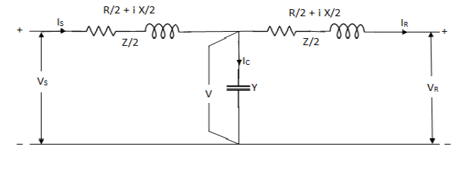
Z = R + i X


VS=Vr(1+YZ/2)+Ir(Z(1+YZ/4))-----------(2)
From eqn. 1 and 2,

 ohm
ohm

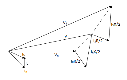
Phasor diagram for Nominal TT Method
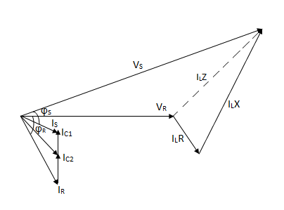
Phasor diagram for Nominal T Method
3) The long transmission line
In case of long transmission line, the expressions for voltage and current at any point on the line are derived. Then based on these equations an equivalent model is obtained for the long line. Let us consider 1 phase of a distributed line of length l km.
Consider a small segment of line∆x at a distance x from the receiving end of the line.
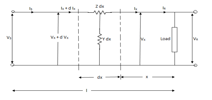


Differentiating eq. 1 wrt x,

Substituting the value of eq. 2 in 3

Eq. 4 is a linear differential eqn. Whose general soln. Can be written as follows:

C1 and C2 are arbitrary constants to be evaluated. Ar = √YZ Propagation constant.
Differentiating eq 5 wrt x


Where Zc = 
The constants C1 and C2 may be evaluated by using the end conditions i.e.
When x = 0, Vx = VR and Ix = IR
VR = C1 + C2


Thus eq 5 and eq 6 can be written as


Here, Zc is called the characteristic impedance of the line and r is called the propagation constant.
Rearranging,


Ix=IR coshrx + VR (1/Zc )sinhrx
Where x = l, Vx = Vs , Ix = Is

Here, A=D=coshrl
B=Zc sinhrl
C =  sinhrl


 after inverting
It must be noted that r = √YZ is in general a complex number and can be expressed as
r =
Consider a single phase load fed from a source


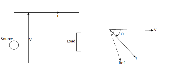
When  is positive, the current lags behind voltage. This is convenient choice of sign of
  in power systems where loads have mostly lagging power factors.
S=VI*
=|V||I|<
=|V||I|cos +i|V||I|sin
=P+iQ


Signifies rating of equipments (Gen, Tran.)
P==|V||I|cos =real power (watts,kW,MW)
Q=|V||I|sin = reactive power (VAR,KVAR,MVAR)
The reactive power is positive for lagging current and negative for leading current.
 = positive for lagging current
= negative for leading current.
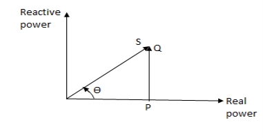
For complex power fed to three phase load,


Where  = power factor angle
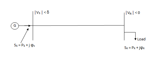
Since loads are more often expressed in terms of real and reactive power, it is convenient to deal with transmission line equations in the form of sending and receiving end complex power and voltages.
Let us take the receiving end voltage as a reference phasor (VR = |VR|<0°) and let the sending end voltage lead it by an angle  (Vs =|Vs|<
 ).
).
The angle  is known as torque angle.
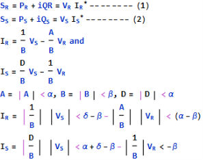
From eqn. 1,


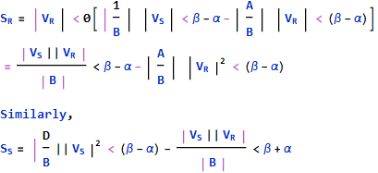 -----------------(4)
In eq 3 and 4, SR, Ss are per phase complex Voltamperes while VR, Vs are expressed in volts per phase.
If VR and VS are expressed in kV line, then the three phase receiving end complex power is given by

From eq. 3 we can write real and reactive powers at the receiving end as


Similarly, from eq 4,


The received power PR will be maximum at

Such that

The corresponding QR (at max PR) is

Thus, the load must draw this much leading MVAR in order to receive the maximum real power.
Consider a short line with a series impedance Z,
A=D+1<0, B=Z=|Z|<


The above short line eqn. Will also apply for a long line when the line is replaced by its equivalent π and the shunt admittances are lumped with the receiving end load and sending end generation.
Thus,


Hence, 
Normally, resistance of a transmission line is small compared to its reactance (since it is necessary to maintain a high effect of transmission) so that 
Where Z=R+iX .The receiving end eqn. Can be approximated as


Assuming  ,
,

|Vs|-|VR| =∆V , the magnitude of voltage drop across the transmission line.

Several important conclusions are:
i) For R=0, the real power transferred to the receiving end is proportional to sin , while the reactive power is proportional to the magnitude of the voltage drop across the line.
Ii) The real power received is maximum for =90˚ and has a value |VS||VR|/ X.
Iii) Maximum real power transferred for a given line (fixed X) can be increased by raising its voltage level.
For very long lines voltage levels cannot be raised beyond the limits, so to increase power transmitted in such cases, the only choice is to reduce the line reactance. This is accomplished by adding series capacitors in the line.
Iv) To maintain a desired voltage profile, the VARS demand of the load must be met locally by employing positive VAR generators.
When the line loaded by terminated impedance equal to its characteristic impedance, the receiving and current is


For a lossless line Zc is purely resistive. The load corresponding to the surge impedance at rated voltage is known as the surge impedance loading given by

Since VR = VL rated / , SIL in MW becomes

It is defined as the load (of Unity power factor) that can be delivered by the line of negligible resistance.
This is useful to give a limit of the maximum power that can be delivered by a line and is useful in the design of Transmission lines. This can be used for the comparison of loads that can be carried on the transmission lines at different voltages.
The power transmitted through a long transmission line can be increased either by increasing the value of receiving end line voltage (VrL) or by reducing Surge impedance or characteristic impedance.
Receiving end power circle diagram for transmission line (assuming ABCD constants are already given) –
The sending end voltage Vs and current Is can be determined if receiving end voltage VR and
Receiving end current IR are known. Such circuits when operated on a fixed frequency, they behave according to a circular function.
The complex power at the receiving end and sending end of a transmission line are given by-
SR = PR + iQR

And Ss = Ps + iQS

The equation 1 can be written for receiving end true and reactive power components as


Squaring and adding above two equations,

Or

The coordinate of the centre of circle and radius of the circle given by the above eqn. Are
x-coordinate of the centre of circle =
y-coordinate of the centre of circle =
Radius of the circle =
At first, the centre of the circle is plotted on a suitable scale. From the centre, an Arc is drawn with the calculated radius. The load line OP is drawn from the origin inclined at an angle  (load power factor angle) with the horizontal.
If the voltages and are taken phase voltages in volts, then the powers indicated on x-axis and y-axis will be in Watts and VARS per phase respectively.
To determine the maximum power, horizontal line is drawn from the centre of the circle intersecting vertical axis at the point L and the circle at the. M.
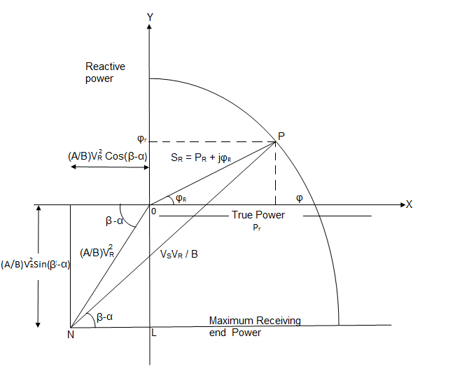
Distance alarm represents the maximum power for the receiving end.
Receiving – End Power Circle Diagram
Numerical
1. A 3 132kV overhead line delivers 50MVA at 132kV and power factor 0.8 lagging at its receiving end. The constants of line A=D+0.98<3˚ and 8=110<75˚ ohm, c = 0.0005<88˚ mho.
Find i) sending end voltage, current, PF and power angle
Ii) sending end active and reactive power.
Soln.
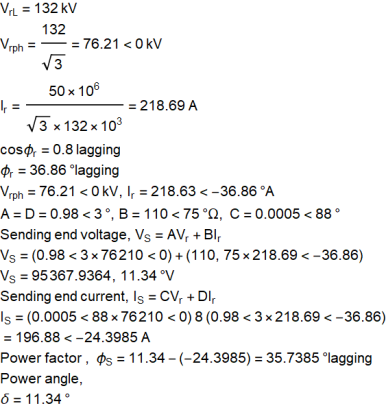
Sending end active and reactive power


2. A 33kV single circuit, 3 phase transmission line has the ABCD parameters A=D=1<0˚, B=11.18<63.43˚ ohm. The line is to believer 7.5 MVA at 0.85 pf lagging at the load end. The receiving end voltage is 32kV (line to line). How much active and reactive power is to be despatched from the sending end?
Soln. Taking receiving and phase voltage a5 ref.


Line parameters,


Sending end current,
IS = CVR+DIR
=0+1<0˚×135.32<-31.8
=135.32<-31.8˚A
Phase angle
 S =2.3˚-(-31.8)=34.1˚
Active Power despatched 

Reactive Power despatched = 
=
3. A typical line has following parameters
A=D=0.96<1.0° and B=100<80° ohm.
a) If the line supplies a load of 30MW at 0.8 pf lag, 110kV, find the sending end voltage and hence the regulation of the line.
b) For a load of 50MW at 0.8 pf lag, 110kV, find the reactive power supplied by the line and by synchronous capacitors if the sending end voltage is 120kV. Also determine the power factor of the line at the receiving end.
c) Find the maximum power that can be transmitted if the sending and receiving end voltages are as in (b).
d) Find the power and pf of the load if the voltages at the two ends are 110kV and having a phase difference of 20°.
Soln. Receiving end phase voltage,

 2A
2A


Sending end phase voltage,


Voltage regulation =
b) Receiving end true power,


Receiving end reactive power,

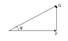

Thus, for VSL = 120kV, VRL = 110kV and PR =50 MW leading MVAR of 3.47 must be drawn from the line along with the true power of 50MW, since the load requires lagging MVAR of 50 tan (cos -1 0.8) i.e. 37.5, the synchronous capacitors must deliver 37.5+3.47 = 40.97 MVAR.
Power factor of the line at the receiving end,

c) For the given values of sending and receiving end voltages, the power transfer will be maximum for . Thus, maximum power transmitted is given as-


d) 


=60.5-22.164 = 38.336 MW
And

=104.789-114.026
=-9.237 MVAR
Load angle, 

The performance of transmission lines, especially those of medium length and longer can be improved by reactive compensation of a series or parallel type.
- Series compensation - It consists of a capacitor bank placed in series with each phase conductor of the line.
Series compensation reduces the series impedance of the line, which is the principle cause of voltage drop and the most important factor in determining the maximum power which the line can transmit.


X= 1 - 
2. Shunt compensation - It refers to the placement of inductors from each line to neutral to reduce partially or completely the shunt susceptance of a high voltage line, which is particularly important at high loads when the voltage at the receiving may otherwise become very high.
3. Synchronous phase modifiers - The synchronous motor can be made to take either a lagging or leading current from the line by altering its excitation.
An idle running synchronous motor can be used for voltage regulating purposes by connecting it in parallel with the load at receiving end of the line.
Depending upon load conditions, the machine runs part of the time with leading current and part of the time with lagging current for voltage regulation.
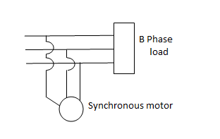
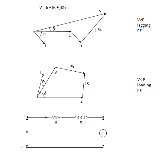
4.Synchronous condenser - The synchronous machines used for power factor improvement are usually referred to as synchronous condenser as they are always required to take a leading current.
Example -
A 100 km, 50Hz, 3 phase line with r = 0.03ohm, X= 0.10 ohm and C = 0.01  F per km of line length has a load of 2 MW at 0.8 power factor lag at the receiving end. The receiving end is maintained at 11kV by connecting at receiving end a bank of static capacitors rated 1 MVAR at 11kV. Calculate using nominal π-method, the voltage and current at the sending end of the line.
Soln. 

For a nominal π-network, the generalised ckt. Constants are


Capacitor current,

Receiving end current,

Sending end voltage,


Sending end current,


Example-
A 200 km, 3 phase, 50Hz transmission line has the following data.
A=D =0.938<1.2°, B=131.2<72.3 ohms/phase, C=0.001<90° siemens/phase. The sending end voltage is 230kV. Determine a) the receiving end voltage when the load is disconnected. b) the line charging current
c) the maximum power that can be transmitted at a receiving end voltage of 220kV and the corresponding load reactive power required at the receiving end.
Soln. Sending end phase voltage,

When the load is disconnected,
Ir = 0
Vs = AVr + BIr
192790<0=(0.938<1.2)×Vr + B×0

Vr = 141570<-1.2V
Vrl =  r =
r =  × 141570 = 245200 V
Line charging current,
Ic = C Vr
=0.001<90˚×141570<-1.2=141.57,88.8 A
Maximum power that can be transmitted for Vrl = 220kV and Vs = 230 kV


Corresponding reactive power required at the receiving end,

Example-
A 3 phase transmission line has a resistance per phase of 5 ohm and an inductive reactance of 15 ohm per phase. Determine the load which the line will be supplying at 132kV and 0.8 pf lagging. The sending end voltage is 140kV.
If a synchronous phase modifier is connected in parallel with the load to improve the power factor to 0.95 lagging, determine the leading MVAR supplied by the synchronous phase modifier. Receiving end voltage and load remain unchanged.
Soln. Power factor of the load, 
Load power factor angle, 
For short transmission line, A=1


For receiving end power circle diagram
Radius of circle = 
Coordinates of the centre of the power circle are
Horizontal coordinate = 

Vertical Coordinate =

Take scale 1 cm = 200MW horizontally and 1cm = 200MVAR vertically.
Radius of the circle = 1168.8 / 200 = 5.85 cm
Horizontal coordinate = -347.8 / 200 = -1.74 cm
Vertical coordinate = -1045.6 / 200 = -5.23 cm
And draw circle diagram.
From origin 0, draw a line OP inclined at an angle cos-1 0.8 =36.9° with the horizontal cutting the circle at pt. b.
From point b, draw a perpendicular ba on the horizontal axis.
Power supplied at 0.8 pf lagging = Oa = 0.3×200 = 60 MW
Now draw another line OP' inclined at angle cos-1 0.95 = 18.2° with the horizontal cutting the vertical line ba at c.
Total leading MVAR supplied by the synchronous phase modifier
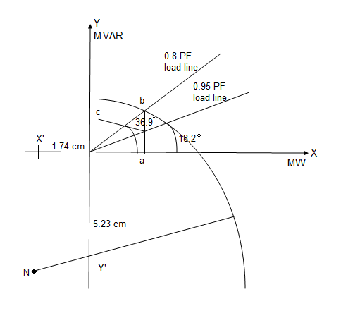
=bc = 0.1 ×200 = 20 MVAR
Example
A 132 kV, three phase line has the following line parameters.
A=0.98<30°, B=110<75° ohm per phase. If the receiving end voltage is 132kV, determine sending end voltage and power angle if a load 50MVA at 0.8 pf lagging is being delivered at receiving end.
Soln. Given data, VrL = 132 kV A = 0.90<30˚ B=110<75˚ S = 50 mVA
P.F cos =0.8 lagging Vs= ?
Vs = AVr + BIr -----------(1)
Is = CVr + DIr -----------(2)
Sending end voltage (Vs) = AVr + BIr
Vrp = 


Example-
Determine sending end complex power of a transmission line delivering 50mVA at 132kV, 50Hz and 0.8 pf lagging. The ABCD constants of transmission line are A=D=0.9855<0.32, B=67.68<68.6g ohm.
Soln. Given data-
S=50 MVA
VL = 132kV
f = 50 Hz
p.f. = 0.8 lagg
A = D = 0.9855<0.32
B = 67.68 < 68.69 ohm


OR


AD – BC =1


=


Reference Books :
- [R1] H. Hadi Sadat: Power System Analysis, Tata McGraw-Hill New Delhi.
- [R2] G. W. Stagg and El- Abiad – Computer Methods in Power System Analysis – Tata McGraw
Hill, New Delhi.
3. [R3] M.E.El-Hawary, Electric Power Systems: Design and Analysis, IEEE Press, New York.
4. [R4] Rakash Das Begamudre, “Extra High voltage A.C. Transmission Engineering”, New age
Publication.
5. [R5] M.A.Pai, Computer Techniques in Power System Analysis, Tata McGraw Hill Publication.
6. [R6] Stevenson W.D. Elements of Power System Analysis (4th Ed.) Tata McGraw Hill, New
Delhi.
7. [R7] K.R.Padiyar: HVDC Transmission Systems, New Age International Publishers Ltd, New
Delhi.
8. [R8] Olle I. Elgard – Electric Energy Systems Theory – Tata McGraw Hill, New Delhi.
9. [R9] V. K. Chandra, Power Systems, Cyber tech Publications.
10. [R10] NPTEL Web course and video course on power system analysis.