Unit - 1
Basics of Control System
A control system is a set of mechanical or electronic devices which control the other devices. In control system behaviors of the system is desired by differential equations.
- Open Loop control System:
This is the loop of control system without any feedback. In this the control action is not dependent on the desired output.

Fig. Open loop control system
Example of open Loop systems are the traffic signals, Automatic washing machine and in fields control d.c motor.
- Closed Loop control system:
This is a type of control system with feedback. In this type of system, the control action is dependent on the desired output.

Fig. Closed Loop control system
The error signal is again fed to controller to the error and get desired output
- Feedforward System:
The feedback system is which work to reduce the error it’s the system. In some system where the disturbances input can be provided beforehand, its effect can be eliminated by feedforward system.
- Tracking System:
The main objective of such system is to trace any particular location as direction of a target id value on continuous basic. The basic examples of tracking, Range tracking, Tracking in phased array radars.
- Regulator System: The main objective of such systems is to maintain a designated characteristic they try to maintain a range of values is a machine for ex. Voltage regulator etc.
The transfer function of a linear time invariant system is the ration of Laplace transform of the output to input.
(a) For open Loop system

G(s) = c(s)/R(s) -------(1)
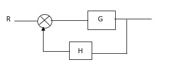
(b) For closed Loop system

G(s) – forward amplification
H(s) _ Reverse amplification
Above system is with negative feedback.
Positive feedback are used only in oscillators and other use is not known as discussing only negative feedback.
[ R(s) – c(s) H (S) ] G(s) = c(s)
R (s) G(s) = [1+G(s) H(s)] c(s)
C(s)/R(S) = G(S)/1+G(s) H(s)
So, the transfer function of closed Loop system is
C(s)/ R(S) = G(s)/ 1+G(S) H(S) --------(2)
If numerator of above equation (2) is equalized to zero we get zeros of closed Loop Transfer function [G(S) = 0]
If dominator of equation (2) is equaled to zero we get polls of the closed loop transfer function [ 1+G(s) H(S) = 0]
1+ G(S) H(s) = 0 [ characteristic Equation]
Stability of the system is determined by the location of its poles.
The transfer function of a linear time invariant system is the ratio of Laplace Transform
The transfer function can be represented by the ratio of two polynomials
G (S) = a0sn+a1 sn-1-------+an/b0sm+b1sm-1+-----+bn
a0—an ---- constants
G(S) = K(s+z1) (s+z2) (as2+bs+c)/(S+A) (s+p2) (As2+Bs +c)
K= a0/b0 (Gain of system)
For poles –They are the values of s for which
G(S)
(S+p1)(S+p2)(A
S= p1, -p2 ,-B± B2-4Ac/2A
The transfer function can be represented by the ratio of two polynomials
G (S) = a0sn+a1 sn-1-------+an/b0sm+b1sm-1+-----+bn
a0—an ---- constants
G(S) = K(s+z1) (s+z2) (as2+bs+c)/(S+A) (s+p2) (As2+Bs +c)
K= a0/b0 ( Gain of system)
For ZEROS – They are the values of s for which
G(S)
S=-z1, -z2 ,-b± b2-4ac/2a
(1) Location of poles and zeros in s place determines the reliability of the system
(2) There can be multiple poles and zeros
(3) The numerator of transfer function when equalized to zero gives zero of system
(4) The denominator of transfer function which equalized to zero gives poles of system.
Mechanical System
(a) Translational system
(b) Rotational system
(a) Translational system
The motion that takes place along a straight line is called translational the forces that resist motion are
(i) Inertia: A body with mass ‘N’ acceleration ‘a’ will produce inertia fm(t)= malt N’ acceleration ‘a’ will produce inertia
fm(t)= M a(t)
In terms of velocity
Fm(t) = M dv(t)/dt
In terms of displacement
Fm(t)= Md2/dt2µt
(ii) Damping force: The damping force is proportional to velocity for vis case function
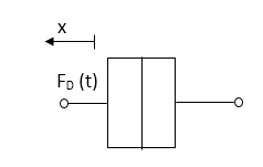
F0(t) = B(t) = B dx(t) /dt
B Damping coefficient N/M sec
(iii) Spring force: A spring stores potential energy. The releasing force of a string is proportional to the displacement.

Fk(t)  x(t)
x(t)
Fk(t) = k x (t)
Fk(t) = k 
K = string constant N/m.
(b)Rational System: The motion of a body about a fixed axis is called as Rotational motion The types of torques which can resist the motion are
i) Inertial Torque: The inertial torque is the product of moment of inertia I and angular acceleration.
TI(t) = J (t)
(t)
TI(t) = Jd/dt w(t)
TI(t) = Jd2ø(t)/dt2(N-m)
W (t) – Angular velocity
Ø(t) = Angular displacement
(ii) Damping Torque: it is product of damping efficient B and angular velocity w
T0 (t) = B w(t)
T0(t) = B d/dt ø(t)
(iii) Spring Torque: It is the product of torsional stiffness and angular displacement
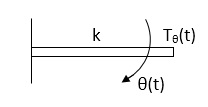
Tø(t) = k ø(t)
K = N.m/rad
Electrical System
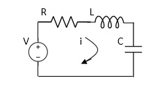
Applying Kirchoff’s voltage Law
V= Ri +Ldi/dt +1/c
V= Rdq/dt + L d2q/dt2+q/c
Now By kirchoff’s current low
I= V/R+ 1/L  + cdv/dt
But V= dø/dt
I= 1/R dø/dt + 1/L ø+cd2ø/dt2
But v= dø/dt
I= 1/R dø/dt+ 1/L. ø+c d2ø/dt2
Force -voltage | Force -current | Mechanical Translatory | Mechanical Rotational |
1.Voltage (v) | Current | Force (f) | Torque (T) |
2.Charge(q) | Flux (ø) | Displacement(x) | Angular Displacement(ø) |
3.current. | Voltage | Velocity v(t) | Angular velocity(w) |
4.Inductance(l) | Capacitance(c) | Mass (m) | Moment of inertia (J) |
5. Resistance(R) | Conductance G= (1/R) | Damping coefficient (B) | Damping Coefficient (B) |
6.Reciprocal of capacitance(1/c) | Inverse of Inductance (1/L) | Stiffness (K) | Stiffness(K) |
- Block in cascade

- Moving summing point after a block

2. Moving summing point ahead of block

3. Moving take off point after a block

4. Moving take off point ahead a block

5. Eliminating a feedback Loop

Block Diagram

SFG
Q:
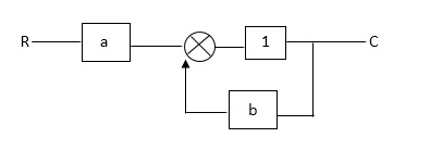
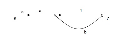
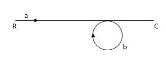
Ra+cb =c
c/R= a/1-b
RULES:
1) The signal travels along a branch in the direction of an arrow.
2) The lip signal is multiplied by the transmittance to obtain the o/p.
3) I/p signal at a node is sum of all the signals entering at that node.
4) A node transmits signal at all branches leaving that node.
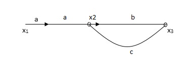
Q. The SFG shown has forward path and singles isolated loop determine overall transmittance relating X3 and X1?
Sol:
X1- I/p node
X2-Intenmediale node
X3- o/p node
Ab- forward path (p)
Bc- 1 loop (L)
At node XQ:
X2 = x1a + x3c [Add i/p signals at node]
At node x3:
x2b =x3
(x1a+x3c) b = x3
X1ab = x3 (1-bc)
X1 = x3 (1-bc)/ab
Ab/(1-bc) = x3/x1
T= p/1-L

X1:- I/p node x2, x3,x4,x5,Qnlexmedili node
X0:- o/p node abdeg:- forward path
Bc, ef :- Loop [isolated]
x2 = ax1+c x3
x3= bx2
x4 = d x3+f x5
x5 = e x4
x6= g x5
x6 = g(e x4) = ge [dx3+ e f x5]
xb = ge [d (bx2) + f (e x4)]
xb = ge [ db (ax1+cx3) + fe (dx3+ fx5)]
xb = ge [db (ax1+cb (ax1+x3) +fe[cdbx2]+
f( e [db (ax1+ cx3)
x2 = ax1 + cb (x2) x4 = d bx2 + f exq
x2 = ax1 + cbx2 = db (d4) + fe/1-cb
x2 = ax1/(1-cb) xy = db x2 + f x6/g
xy = db [ax1]/1-cb + f xb/g
x5 = c db( ax1)/1-cb + efxb/g
xb = gx5
= gedb (ax1)/1-cb + g efxb/g
Xb = gx5
Gedb (ax1)/1-cb + g efxb/g
(1- gef/g) xb = gedb ax1/1-ab
Xb/x1 = gedb a/ (1- ef – bc + beef
Xb/x1 = p/ 1- (L1+L2) + L1 L2 for isolated loops
T= 
The overall transmittance Coverall gain can be determined by Masks formula.
Explanation:
Pk forward path transmittance of k+n path from a specified i/p node to n o/p nods
While calculating ipnode to n o/p nods.
While calculating ip no node should be encountered (used) more than ones.
 it is the graphics determined which involves of transmittances and multiple increases b/w non touching loops.
 = 1- [sum of all individual loop transmitting]
+[ sum of loop transmittance product of all possible non- touching loops]
-[sum of loop transmittance of all possible triples of non- touching loops]
 path factor associated with concerned path & involves all a in the graphic which are isolated from forward path under consideration.
The path factor  for kth is equal to graph determinant of SFG which effect after erasing the kth path from the graph
Q.
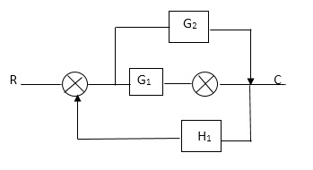
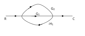
P1= G1 p2 =G2 Delta1 =1
L1= -G1 H1
 = 1-(-G1H1)
= 1+G1H1
T= G1+G2/1+G1H1
Ques: Determine overall gain reliably x5 and x1 Draw SFG
X2 = ax1+ f x2
X3= bx2 +exy
X4 = cx3+hx5
X5 =dx4 + gx2
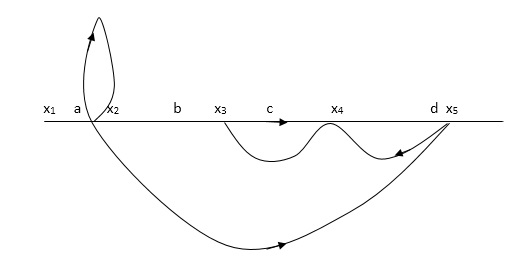
P1 = abcd p2 = ag
L1 = f L2 = ce, L3= dh
 1 = 1
1 = 1
 2= 1-ce
 = 1-[L2+L2+L3] + [L1 L2 +L1 L3]
= 1-[f+ le = dh] + [fce +fdh]
1-T= abcd+ ag (1-ce)/1-[ftce + dh ] + (fce + fdh)
References:
1) B. C. Kuo, “Automatic Control System”, Wiley India, 8th Edition, 2003.
2) Richard C Dorf and Robert H Bishop, “Modern control system”, Pearson Education, 12th edition, 2011.
3) D. Roy Choudhary, "Modern Control Engineering", PHI Learning Pvt. Ltd., 2005.