Unit - 5
Capacitance of Transmission Line
Consider long straight cylindrical conductor A of radius r metres. Let the conductor operate at such a potential (VA) that charge QA coulombs per metre exists on the conductor. It is desired to find the expression for VA. The electric intensity E at a distance x from the centre of the conductor in air is given by:
E = QA/ 2π x  volts/m
QA= charge per metre length
 = permittivity of free space
As x approaches infinity, the value of E approaches zero. Therefore, the potential difference between conductor A and infinity distant neutral plane is given by :
VA =  / 2π x
  dx = QA/ / 2π

Key Takeaways:
Since the electric field is equal to the rate of change of potential, this implies that the voltage inside a conductor at equilibrium is constrained to be constant at the value it reaches at the surface of the conductor.
Consider a group of long straight conductors A, B, C etc. operating at potentials such that charges QA, QB, Qc etc. coulomb per metre length exist on the respective conductors
Let us find the potential at A VA in this arrangement.
Potential at A due to, its own charge (i.e. QA)
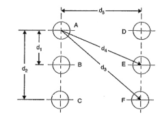
Figure 1. Potential at conductor
=  A/ 2π x
  dx ---------------------------------(i)
Potential at conductor A due to charge QB
 B/ 2π x
  dx ---------------------------------------(ii)
Potential at conductor A due to charge Qc.
 / 2π x
  dx --------------------------------------(iii)
Overall potential difference between conductor A and infinite neutral plane is
VA = (i) +(ii) +(iii)
=  A/ 2π x
  dx +
dx +  B/ 2π x
  dx +
dx +  / 2π x
  dx
dx
= 1/ 2π  [ QA( log e ∞ - log e r) + QB( log e ∞ - log e d1) + Qc(log e ∞ - log e d2) +………………………]
= 1/ 2π  [ QA log e 1/r + QB log e1/d1 + Qc log e 1/d2+ log e (QA+QB+QC) +……..]
Key Takeaways:
The potential at a point on the surface is created by the charge distribution of all the other points on the surface.
Consider the single-phase line consisting of two round conductors as shown in Figure. The separation between the conductors is D .
Let us assume that conductor 1 carries a charge of q1 C/m while conductor 2 carries a charge q2 C/m. The presence of the second conductor and the ground will disturb field of the first conductor. However we assume that the distance of separation between the conductors is much larger compared to the radius of the conductor and the height of the conductor is much larger than D for the ground to disturb the flux.
Therefore, the distortion is small and the charge is uniformly distributed on the surface of the conductor.
Assuming that the conductor 1 alone has the charge q1 , the voltage between the conductors is
V12(q1) = q1/ 2 π  o ln D / r1 ---------------------------------------------------------(1)
Similarly if the conductor 2 alone has the charge q2 , the voltage between the conductors is
V21(q2) = q2/ 2 π  o ln D / r2
The above equation implies that
V12 (q2) = q2/ / 2 π  o ln r2/D --------------------------------------------------(2)
From the principle of superposition we can write
V12 = V12(q1)+V12(q2) = q1/ 2 π  o ln D / r1 + q2/ / 2 π
  o ln r2/D ------------(3)
For a single-phase line let us assume that q1 (= -q2 ) is equal to q . We therefore have
V12 = q/ 2 π  o ln D / r1 - q/ / 2 π
  o ln r2/D = q/ 2 π
  o ln D 2 / r1 r2 -------------(4)
Assuming r1 = r2= r3, we can rewrite (4) as
V12 = = q/ π  o ln D / r ----------------------------------------------------(5)
Therefore the capacitance between the conductors is given by
C12 = π  o ln D / r F/m -----------------------------------------------------(6)
The above equation gives the capacitance between two conductors.
For the purpose of transmission line modeling, the capacitance is defined between the conductor and neutral. This is shown in Figure. Therefore, the value of the capacitance is given from Figure as
C=2C12 =2 π  o/ ln (D / r) F/m ------------------------------------------------(7)

Figure 2.Fig (a) Capacitance between two conductors (b) Equivalent capacitance to ground
Capacitance of single phase line with effect of earth’s surface on electric field.
Assume conductors A’ and B’ as image conductors of conductors A and B respectively, as shown in Figure. Let the height of conductors be h metres above the earth and charge of +q coulombs per metre length and -q coulombs per metre length on the conductors A and B respectively.
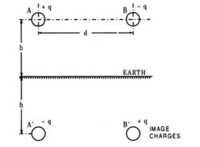
Fig 3. Single phase transmission lines
The equation for the voltage drop VAB as determined by two charged conductors A and B and their images A’ and B’ may be written as follows:
VAB = 1/ 2π [ qa log e d/r + qb log e r/d + qa’ log e √4h2 + d2 / 2h + qb’ log e 2h/ √4h2 + d2 ] ----------------------------------------------------(8)
Substituting qA = q’B = + q and q’A = qB = -q we have,
VAB = q/ π log e 2hd/ r √ 4h2 + d2
Capacitance between conductors A and B,
CAB = q/VAB = π / log e d/ r√ 1+ d2/4h2 -----------------------(9)
The above expression for capacitance reveals that the presence of earth modifies the radius of conductor r to r √ ( 1 + d2 / 4 h2 )
The effect of earth on the capacitance of the system is to increase it. However, normally the distance of separation between the conductors is much smaller than the height of the conductor from the ground, therefore, r √ ( 1 + d2 / 4 h2 ) ≈ r and for all practical purposes the effect of earth on line capacitance can be neglected.
Key Takeaways:
For transmission line modelling purpose the capacitance is defined between the conductor and neutral
GMD & GMR stands for Geometrical Mean Distance and Geometrical Mean Radius. This concept is useful in Power System for the calculation of Inductance and Capacitance of Transmission Line.
Let us assume two composite conductors used in Transmission Line as shown in figure below.
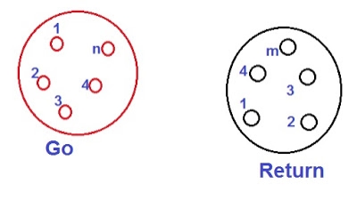
Figure4. Composite conductors
As shown in the figure above, one conductor is Go and another is Return for current for single phase line. The current is assumed to be equally divided among all the strands of a conductor.
Therefore,
Current carried by each strand in Go conductor = I/n
Current carried by each strand in Return conductor = -I/m
Here I is the total current carried by each conductor.
To calculate the GMD and GMR for the configuration of the conductors shown in figure above.
For getting the GMD, first we need to calculate the distance between the strands of Go and Return conductors.
Let,
D11 = Distance between the 1ststrand of Go and Return conductor
D12 = Distance between the 1ststrand of Go and 2nd strand of Return conductor
D21 = Distance between the 2nd strand of Go and 1st strand of Return conductor
Dmn = Distance between the mthstrand of Go and nth strand of Return conductor
Thus, the geometrical mean of above distances that is GMD
= mn √ (D11D12…….D1m)(D21 D22….D2m) (D31 D32….D3m) …..(Dn1Dn2…Dnm)
Geometrical Mean Radius of a solid conductor or a strand of radius R is defined as the factious radius R’ having no internal flux linkage but having the same inductance as the original conductor of radius R.
R ‘ = 0.7788R
Method for Calculating GMR of a Composite Conductor :
For calculating GMR, first we find the distance between the individual strands. Thus, if there are n strands in a composite conductor then obviously there will be n2 distances between the strands.
Thus GMR of Go conductor
= n2 √ (R’ D12 D13…..D1n) (R’D21 D22 D23 ….D2n) …..(R’Dn1Dn2….D(n-1)n)
As shown in figure below, go conductor contain three strands of radius 2.5 mm while the return conductor contains two of radius 5mm.
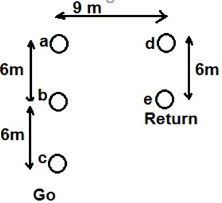
Figure5. Conductor strands
GMR of individual strands in Go conductor R’ = 0.7788xR
= 0.7788×2.5
= 1.947mm
GMR of Go Conductor
= [(1.947x6x12)(1.947x6x6)(1.947x6x12)]1/9
= 0.4809m
Similarly,
GMR of individual strands in Return conductor R’ = 0.7788xR
= 0.7788×5 mm
= 0.003894 m
Hence, GMR of Return Conductor
= [(0.003894×6)(0.003894×6)]1/4
= 0.1528 m
Now, distance between strand a and e Dae = [92+62]1/2
= 10.81 m
Distance between strand c and d, Dcd = [92+122]1/2
= 15 m
Therefore,
GMD for the configuration,
= [9×10.81×10.81x9x15x10.81]1/6
= 10.74 m
Need for transposition for capacitance solutions:
The basic definition for transposition of transmission line is to rotate the conductors which result in the conductor or a phase being moved to next physical location in a regular sequence. In electrical power transmission lines, the conductor arranges unequal space. So, the voltage drops are not same as one place to another.
To eliminate this effect, we can simply do by interchange the conductor position which is known as transposition. The transposition arrangement is necessary when there is a capacitance between the power conductor.
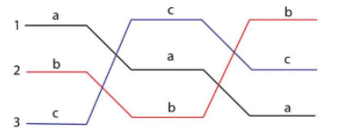
Figure6 . Transposition
Key Takeaways:
GMD and GMR
This concept is useful in Power System and used for calculation of Inductance and Capacitance of Transmission Line. To get GMD,we need to calculate the distance between the strands of Go and Return conductors.
Figure shows the three identical conductors of radius r of Capacitance of Three Phase Line Unsymmetrical Spacing.
It is assumed that the line is fully transposed. As the conductors are rotated cyclically in the three sections of the transposition cycle, correspondingly three expressions can be written for Vab. These expressions are:
For the first section of the transposition cycle
Vab = 1/ 2 πk (qa1 ln D12/r + qb1 ln r/ D12 + qc1 ln D23/ D31 )--------(a)
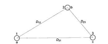
Figure7. Cross section of three phase line with asymmetrical spacing (fully transposed)
For the second section of the transposition cycle
Vab = 1/ 2πk (qa2 ln D23/r + qb2 ln r/D23 + qc2 ln D31/D12) -----------(b)
For the third section of the transposition cycle
Vab = 1/ 2 πk (qa3 ln D1/r + qb3 ln r/ D31 + qc3 ln D12/D23) -----------------(c)
If the voltage drop along the line is neglected, Vab is the same in each transposition cycle. On similar lines three such equations can be written for Vbc = Vab ∠ –120°. Three more equations can be written equating to zero the summation of all line charges in each section of the transposition cycle.
From these nine (independent) equations, it is possible to determine the nine unknown charges.
With the usual spacing of conductor’s sufficient accuracy is obtained by assuming
Qa1 =qa2=qa3=qa; qb1=qb2=qb3=qb; qc1=qc2=qc3=qc
This assumption of equal charge/unit length of a line in the three sections of the transposition cycle requires, on the other hand, three different values of Vab designated as Vab1, Vab2 and Vab3 in the three sections. The solution can be considerably simplified by taking Vab as the average of these three voltages, i.e.
Vab (avg) = 1/3 (Vab1 + Vab2 + Vab3)
Vab = 1/ 6πk[ qa ln (D12 D23 D31/ r3 ) + qb ln ( r3 / D12 D23 D31) + qc ln ( D12 D23 D31/ D12 D23 D31)]
= ½ πk(qa ln Deq/r + qb ln r/ Deq) ------------------------------------(1)
Deq = (D12D23D31) 1/3
Vac = 1/ 2 π k ( qa ln Deq/r + qc ln r/ Deq) -----------------------------(2)
Adding Eqs. (1) and (2), we get
Vab + Vac = 1/ 2 π k ( qa ln Deq/r + (qb+qc) ln r/ Deq)-------------(3)
For balanced three-phase voltages
Vab + Vac = 3 Van
(qb +qc) = -qa
Use of these relationships in Eq. (3) leads to
Van = qa / 2 π k ln Deq/r -------------------------------------------------------(4)
The capacitance of line to neutral of the transposed line is then given by
Cn = qa / Van = 2 π k/ ln (Deq/r)------------------------------- (4a)
For air medium (kr = 1)
Cn = 0.0242 / log (Deq/r) μ F/km to neutral
It is obvious that for equilateral spacing Deq = D, the above (approximate) formula gives the exact result .
The line charging current for a three-phase line in phasor form is
Ia (line charging) = jw Cn Van A/km
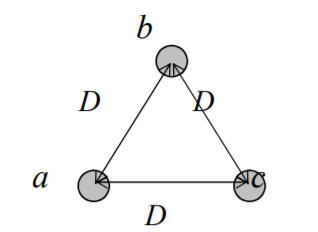
Figure 8. Symmetrical spacing
Vab = ½ π  ( qa ln D/r + qb ln r/D + qc ln (D/D))
Vac = ½ π  ( qa ln D/r + qb ln D/D + qc ln (r/D))
Vab + Vac = ½ π  ( 2qa ln D/r +( qb+qc) ln (r/D)
But qb + qc = -qa
Vab + vac = 1/ 2π ( 2qa ln D/r – qa ln r/D)
= 1/ 2π ( qa ln (D/r) 2 – qa ln r/D) = 1 / 2π
 ( qa ln (D/r) 3)
= 3qa / 2π ln D/r volts
Phasor
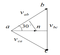
Figure 9. Phasor diagram
 = |vab|
  30
30
|vab| /2 = Van cos 30
= √3/2 Van
|vab | = √3 Van
 =√3 van
  30
30
 = -
= -  =√3 van
  -30
-30
 +
+  = √3 van
  30 + √3 van
  -30
-30
√3 van x 2 x cos 30 = √3 van x √3 = 3 Van
Key Takeaways:
In a Capacitance of Three Phase Overhead Line, the capacitance of each conductor is considered instead of capacitance from conductor to conductor.
In a Capacitance of Three Phase Overhead Line, the capacitance of each conductor is considered instead of capacitance from conductor to conductor. Here two cases arise symmetrical spacing and unsymmetrical spacing.
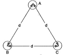
Figure 9. Symmetrical Spacing
1.Symmetrical Spacing:
Fig. Shows the three conductors A, B and C of the 3-phase overhead transmission line having charges QA, QB and QC per metre length, respectively. Let the conductors be equidistant (d metres) from each other. We shall find the capacitance from line conductor to neutral in this symmetrically spaced line.
VA =  / 2π
/ 2π  dx +
dx +  / / 2π
  dx +
dx +  / 2π x
  dx
dx
= 1/ 2 
 [ QA log e 1/r + QB log e 1/d + Qc log e 1/d ]
= 1/ 2 
 [ QA log e 1/r + (QB + QC ) log e 1/d]
Assuming Balanced supply, we have
QA + QB + QC =0
QB + QC = -QA
VA = 1/2π [ QA log e 1/r – QA log e 1/d] = QA / 2 π
 log e d/r volts
Capacitance of conductor A w.r.t neutral,
CA = QA / VA = QA / QA / 2π log e d/r F/m = 2
 o/ log e d/r F/m
CA = 2π  / log e d/r F/m
2.Unsymmetrical Spacing:
Figure shows a 3-phase transposed line having unsymmetrical spacing. Let us assume balanced conditions i.e. QA + QB + QC = 0.

Figure 10. Unsymmetrical spacing
Considering all the three sections of the transposed line for phase A,
Potential of 1st position,
V1 = 1/ 2 π  ( QA log e 1/r + QB log e 1/d1 + Qc log e 1/d3 )
Potential of 2nd position,
V2 = 1/ 2 π  ( QA log e 1/r + QB log e 1/d1 + Qc log e 1/d3 )
Potential of 3rd position,
V3 = 1/3 (V1 + V2 +V3)
= 1/3 x 2 π  * [ QA log e 1/ r3 + (QB +QC) log e 1/d1 d2 d3 ]
Average voltage on conductor A is
VA = 1/3 (V1 + V2 + V3)
= 1/ 3 x 2 π  * [ QA log e 1/r3 + (QB +QC) log e 1/ d1 d2 d3]
AS QA + QB + QC =0 , therefore QB + QC = -QA
VA = 1/ 6 
 [ QA log e 1/r3 – QA log e 1/ d1 d2 d3 ]
= QA / 6 
 o log e d1 d2 d3 / r3
1/3 x QA/ 2 π log e d1d2d3/r3
= QA/ 2 π log e (d1d2d3/r3 ) 1/3
= QA/ 2 π log e (d1d2d3) 1/3 /r
Capacitance from conductor to neutral is
CA = QA / VA = 2 π / log e 3√ d1 d2 d3 / r F/m
Double circuit
Consider the arrangement shown in figure. It consists of three phase double circuit. The radius of each conductor r. The voltage between the phases a and b can be calculated in order to calculate capacitance. One complete cycle of transposition is shown in figure.
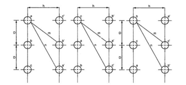
Figure 11. Double circuit
Vab1 = 1/ 2 π { qa ( ln D/r + ln m/n) + qb(ln r/D + ln h/m) + qc ( ln D/2D + ln m/h)}
Vab2 = 1/ 2 π { qa ( ln D/r + ln m/n) + qb(ln r/D + ln h/m) + qc ( ln D/2D + ln m/h)}
Vab3 = 1/ 2 π { qa ( ln 2D/r + ln h/n) + qb(ln r/2D + ln n/h) + qc ( ln D/D + ln m/m)}
Vab = 1/3 { Vab1 + Vab2 + Vab3}
= 1/6π { qa(ln 2D3 / r3 + ln m2h/n2h ) + qb(ln r3 / 2D3 + ln n2h / m2 h) + qc( ln 2D3/2D3 + ln m2h/m2h)}
Vab = 1/6π { qa(ln 2D3 m2/ r3 n2+ ln m2h/n2h ) + qb(ln r3 n2/ 2D3m2 )
Similiarly we have
Vab1 = 1/ 2 π { qa (ln D/
Vac = 1/6 { qa ln 2 D3 m 2 / r3 n2 + qc ln r3 n3 / 2 D 3 m 2 }
We have Vab Vac= 3 Van
3 Van = 1/6 π { 3 qa ln 2 D3 m2 / r3 n2 }
Van = 1/6 {qa ln 2 D3 m2 / r3 n2 }
Can = qa/Van = 6 / ln 2D3 m2 / r n2
Can = 2π / ln { 2 1/3 (D/r) (m/n) 2/3 }
Symmetrical Spacing
Consider a three phase double circuit connected in parallel with conductors A’, B’, C’ forming another circuit.
Let the charge over conductors A, B and C be q1,q2 and Q3 couloms per metre length. Then charge over conductors A’,B’ and C’ will obviously be q1,q2 and q3 per metre length and q1+q2+q3=0 .
VAN = 1/ 2π [ q1
[ q1  + q2
+ q2  + q3
+ q3  + q1
+ q1  + q2
+ q2 + q3
+ q3 ]
]
= 1/ 2π [ q1 log e
  -q1 log e r + q2 log e d + q3 log e
  - q2 log e d + q3 log e
  d + q1 log e
  - q1 log e 2d + q2 log e
  - q2 log e √3d + q3 log e ∞ - q3 log e d]
= 1/ 2π [ 2(q1+ q2 + q3) log e
  + q1 log e 1/2dr + q2 log e
  d 2 + q3 log e 1/
 d 2]
d 2]
= 1/ 2π [ q1 log e 1/2dr + q2 log e 1/
  2 + q3 log e 1/√3 d2 ]
Since q1 + q2 +q3=0
= 1/ 2π [ q1 log e 1/2dr + (q2+q3) log e 1/
  2 ]
2 ]
= 1/ 2π [ q1 log e 1/2dr -q1 log e 1/
  2 ]
2 ]
q 1 / 2π log e
log e  2 /2 dr = q1 / 2π
 log e √3 d / 2r volts
Key Take Aways .
The density of charge on either conductor will be practically unaffected by the charge on the other conductor and will, therefore, be uniform throughout the length.
References:
- Power System Engineering Book by D.P. Kothari and I.J. Nagrath
- Power System Analysis and Design Book by J. Duncan Glover and Mulukutla S Sarma
- A Course In Power Systems Book by J. B. Gupta
- Modern Power System Analysis Book by D.P. Kothari and I.J. Nagrath
- Electrical Power Systems Book by Murty P.S.R
- Elements of Power System Analysis Book by William D. Stevenson