Unit - 3
Per unit system and Load Flow Analysis
In case of large power system, the resistances inductances and capacitances at various components such as generator, Transformer, transmission line are to be considered. The voltage, current and power rating of these components may be different at every level. Hence it is very difficult to represent power system by a simple circuit. Therefore, calculations become more complicated.
To simplify the calculations, actual values of a quantity are usually expressed as fraction of base values such as rated or full load value. These actions are called as per unit values.
Per unit value of any quantity is defined as the ratio of the actual value in any units to the base or reference value in the same units.

Per unit value is unitless quantity.
Per unit system applied to single phase system
Voltage, current, volt ampere and impedance are so related that selection of base of any two quantities determines the base of remaining two quantities.
Let common mega volt ampere base = (MVA)B.
Base voltage on any section of power system=kV
Then the base current and base impedance can be calculated as


If the impedance of considered section is expressed in ohm, then


Similarly, Resistance and Reactance which are expressed in ohms can be written in pu system as


Impedance and Reactance diagram
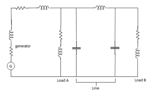
In order to analyse a system, it is necessary to draw its equivalent circuit i.e. impedance diagram.
1) A generator is represented by an EMF in series with the impedance.
2) A short line is represented by its series impedance.
3) Medium and long lines are represented by nominalπ circuits.
4) Very long lines are represented by equivalent π circuits.
5) A static load is represented by their equivalent circuits.
Per unit system applied to 3 phase system
Let common mega volt ampere base = (MVA)B
Base voltage of any section of power system = (kV)B (Line to line)
Then, base current and base impedance can be calculated as


If the impedance of considered section expressed in ohm, then


Similarly, resistance and reactance which are expressed in ohm can be written in pu system as


Change of base of per unit quantity
It is sometimes necessary to convert per unit quantities from one place to another.
Old base-
Let common Mega volt ampere base=(MVA)B old
Base voltage =(kV)B old
Impedance =Z p.u. Old
New base-
Common Mega volt ampere base =(MVA)B new
Base voltage on selected section =(kV)B new
Then PU impedance is given by

Per unit impedance of two winding transformer
Let us consider an approximate equivalent circuit of two winding transformer referred to primary side.
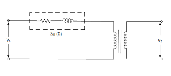
Where, Z01 = impedance of transformer referred to the primary
Let the base is chosen on primary side of transformer.
Common mega volt amp = (MVA)B
Base voltage on primary side =(kV)1B
Then, per unit impedance of transformer referred to primary side is given by

Let us now consider an approximate equivalent circuit of transformer referred to secondary side.
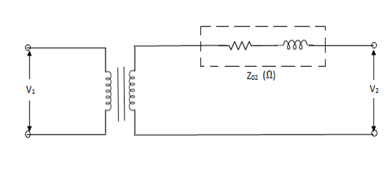
Let common mega volt amp base = (MVA)B
And base voltage of secondary = (kV)2B
Then, per unit impedance referred to secondary


The referred value of impedance on the primary side van be transferred to secondary side as

Substituting eqn. 3 in 2,


In practice, it is often necessary to convert values from one per unit system to another one Example: machine parameters are given in per unit values with respect to machine rating and we want to convert them into per unit values with respect to base values of power system to which machine is connected
This can be done as follows
Per unit value wrt first base: x1 = X/XB,1
Per unit value wrt second base: x2 = X/XB,2
Hence: X = x1 XB,1 = x2 XB,2
→ Conversion from base 1 to base 2:
x2 = x1 [XB,1 /XB,2]
Conversion of an impedance Z from base old to base new
Per unit value wrt first base:

Per unit value wrt second base:

Conversion from base old to base new

A base MVA may be chosen in following manner-
1) It may be equal to MVA of largest equipment in system.
2) It may be equal to sum of all connected MVA.
3) It may be any arbitrary value.
After the selection of the base MVA, the best voltages or each section are to be chosen. The rated voltage of the largest section may be taken as the base voltage for that section.
The base voltages for other sections are then assigned according to the turns ratios of the transformers.
Single line diagram or one line diagram
All power systems are three phase system. If all the equipments of three phases are shown, the diagram will be complicated and difficult to understand. Since all the three phases are exactly similar, the diagram can be simplified by using one phase and neutral. Further simplification is obtained by omitting neutral. Such a diagram is known as single line or one line diagram.
Example.

A bus is a node at which one or more lines or loads or generators are connected.
In a single line diagram, ab bus is shown by a small vertical line. A single diagram cannot show the conditions during unbalanced operation of power system. Whenever it is necessary to show current and voltages during an unbalanced operation, it is necessary to show all the three phase and single line diagram is not sufficient.
Standard symbols for drawing single line diagram
Component | Symbol |
|  |
2. Motor |  |
3. Two winding transformer |  |
4. Three winding transformer |  |
5. Current transformer (CT) |  |
6. Potential transformer (PT) |  |
7. Star connection neutral grounded |  |
8. Circuit breaker |  |
9. Isolator |  |
10. Bus |  |
Advantages of per unit system
1) In per unit System, different voltage level at different components entirely disappears and power system components are expressed only as per unit impedance and voltage.
2) Impedance of machine are specified in terms of percentage of their ratings. Hence, converting it to common base enables for comparison of parameters.
3) It simplifies the computation of power system. The chance of confusion between line and phase values in a balanced three phase system is less.
4) The Per unit impedance referred to either side of transformer is same regardless of their connection.
5) Per unit system is not suitable for computer using digital computers.
Drawbacks of per unit system
Some equations that hold good in unscaled cases are modified when scaled into the Per unit system as factors such as √3and 3 are removed.
Example 1-
A 30 MVA, 11kV generator has a reactance of 0.2 referred to its ratings as bases. Determine per unit reactance when referred to base kVA, new 50000 kVA and base kV of 33kV.
Soln. Old base KVA = 30000kVA
(MVA)B = 30 MVA
Old base kV = 11 kV
Old per unit impedance, Zpu old = 0.2 pu
New base kVA = 50000 KVA
(MVA)B new = 50 MVA


Example-2
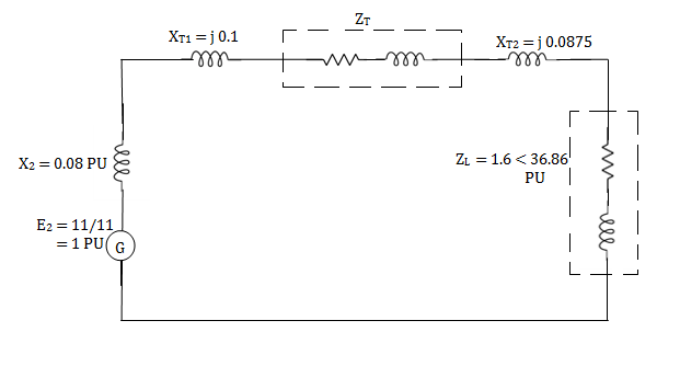
The following system represents a single line diagram of power system. The rating of connected component are given on a single line diagram. Choose 100 MVA common base and 11KV as voltage base on generator site. Draw per unit impedance diagram.


Generator-


Transformer 1-

Transformer 2-

Load-


Load impedance, 


Transmission line-


Example-3
If the resistance in ohm is 5 ohm, find the Per unit value. Given base KVA =10 and base kV=11.
Soln. Base kVA = 10
(MVA)B = 10×10-3 (kV)B = 11


Example-4
A single phase transformer is rated as 2.5kVA, 11/0.4 kV. If the leakage reactance is 0.96ohm when referred to low voltage side, then determine its leakage reactance in per unit.
Soln. (kVA)B = 2.5, (MVA)B = 2.5 ×10⁻³ (kV)B = 0.4


Example-5
Draw the Per unit impedance diagram for the power system shown, neglect resistance and user base of 100MVA, 220kV in 50 ohm line. The rating of the generator motor and transformers are: Generator: 40 MVA, 25kV, X = 20%
Motor: 50MVA, 11kV, X =30%
 : 40 MVA, 33
 -220
-220 kV, X=15%
 30 MVA, 11
 - 220
- 220 kV, X=15%
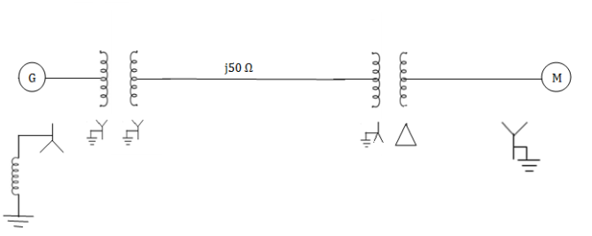
Soln. (MVA)B =100MVA, (kV)B = 220 kV


Example 6
A simple power system is shown in figure. Redraw the system when per unit impedances are represented on a common 5,000 VA base and common system base voltage of 250V.
Soln. Base MVA = 5×10⁻³ MVA
Base kV for generator circuit = 250×10-3 kV
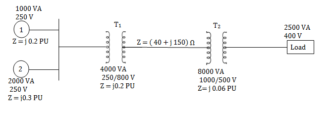
Per unit impedances of machine 1 and 2


Per unit reactance of Transformer T1


Per unit reactance of Transformer T2

Per unit load MVA (pu) = 2.5/5 = 0.5 pu

Example-7
For the system shown in the figure determine the generator voltage. Take the base as 100 MVA, 15kV on generator terminals.

Soln. MVAB = 100 MVA
KVB = 15 kV on generator terminals
Generator-


Load-


Actual generator terminal voltage,


Network topology, driving point and transfer admittance, concept of Z bus and formulation of Y bus matrix using direct method, singular transformation method, introduction to load flow analysis, power flow equations generalisation to end bus systems, classes of buses, Newton- Raphson method (using polar coordinates descriptive), Numerical based on Y bus matrix.
The load flow analysis is the determination of current, voltage, active power and reactive volt ampere at various points in a Power System operating under normal steady state or static conditions.
It is performed to calculate the magnitude and phase angles of voltages at the buses, and also the active power and reactive volt ampere flow for the given terminal or bus conditions.
Node- A terminal of network in a single line segment is called node. E.g. Nodes- 0,1,2,3,4.
Nodes are represented by symbol ‘m’.
In a power system network, out of the m total nodes, one node is always at ground, potential and the remaining n = m – 1 nodes are the buses at which the source power is injected.
Following figure shows the graph of the power network.
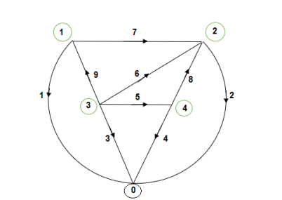
Total no. Of elements, ‘e’ = 9
m = 5
Tree- A connected subgraph containing all the nodes of a graph but having no closed paths is called a tree. The elements of branches b that form a tree are given by and represented by symbol ‘b’ or ‘n’.
b = m – 1 = n (Number of buses)
Following fig. Shows a tree.
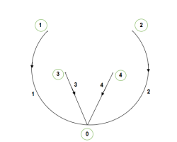
b = m – 1 = 5 – 1 = 4 (n)
Links - Those elements of the graph that are not included in the tree are called link and they form subgraph, not necessarily connected, called cotree. The links are represented by symbol ‘l’.
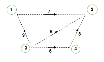
l = e – b = 9 – 4 = 5
Note - A tree (and therefore co-tree) of a graph is not unique.
Let the element i – k connected between the two nodes i and k. This is shown in Figure.
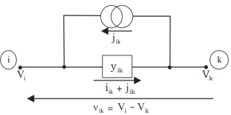
Vi, Vk → ith and kth node voltages respectively vik
Vi – Vik → Voltage across the element i – k
jik → Source current in parallel with element i – k
iik → Self-admittance of the element i – k
ik → Current flowing through the element i – k
Hence, current flowing through the element,
iik + jik = yik vik
For all the elements in a condensed form can be written as
i+j = y v
Where i, j and v are the column matrices of size e × 1 and matrix y is a square matrix of size e × e. The matrix y is known as primitive admittance matrix. The diagonal elements of the matrix yik ik represents self-admittances and off-diagonal elements of the matrix yik ps represents the mutual admittances of the elements ik and ps. If there is no mutual coupling between the elements, the primitive admittance matrix y can be obtained by inverting the primitive impedance matrix z. The matrices z and y are diagonal matrices. In the case, the self-impedances are equal to the reciprocals of the corresponding self-admittances.

If the buses 3 and 4 have mutual element then the corresponding primitive impedance matrix is shown below:

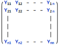
Bus admittance matrix (YBus) for an n-bus power system is square matrix of size n × n. The diagonal elements represent the self or short circuit driving point admittances with respect to each bus. The off-diagonal elements are the short circuit transfer admittances (or) the admittances common between any two number of buses. In other words, the diagonal element yii of the YBus is the total admittance value with respect to the ith bus and yik is the value of the admittance that is present between ith and kth buses. YBus can be obtained by the following methods:
1. Direct inspection method
2. Step-by-step procedure
3. Singular transformation
4. Non-singular transformation
Bus types for power flow analysis
Bus Type Specified variables Unknown variables
Reference bus / Slack bus |Vi|  Pi Qi
Pi Qi
Generator bus or voltage Pi |Vi| Qi 
Controlled bus or PV bus
Load bus or PQ bus Pi Qi |Vi| 
One of the generator buses is selected as the reference bus.
Because the losses in the system remain unknown until the load flow solution is complete, so one of the generator buses is made to take the additional real and reactive powers to supply the transmission losses PL and QL. This bus is therefore known as the slack or swing bus. Since the voltages throughout the system must be closed to 1 per unit, the voltage at the slack bus is assigned to be one per unit.
The voltage of the slack bus is taken as reference and therefore its angle is equal to zero. The slack bus is usually number as bus 1.
Bus Admittance Matrix Y-bus
Consider a small power system network consisting of two generating stations, three transmission lines, one load and a static capacitor connected to a load bus 3. Assume that network is symmetrical and operating under balance conditions.
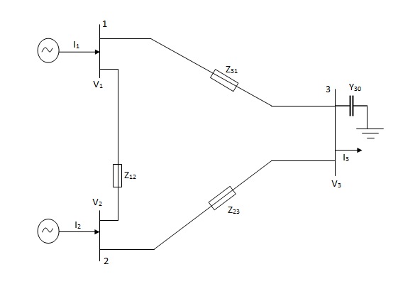


In matrix form,

Where
Y11 = Y12+Y13 Y22=Y21+Y23 Y33=Y30+Y31+Y32
Y12=Y21=-Y12 Y23=Y32=-Y23 Y31=Y13=-Y31
It is to be noted that all injected currents are positive and extracted currents are negative.
The elements Y11, Y22, Y33 forming the diagonal terms are called self admittance. The self inductance of a node x is equal to the sum of admit answers of all the elements connected to node x.
That is
Ypp = Yp1+Yp2+----+Ypm
The elements Y12,Y13,Y21,Y23,Y31,Y32 forming the off diagonal terms are called mutual admittances.
Y12=Y21=-Y12 Y23=Y32=-Y23 Y31=Y13=-Y31
It is to be noted that all mutual admittance terms have a negative sign.
That is, Ypq=-Ypq
For a network having n nodes excluding ground,
I1 = Y11V1 + Y12V2 + -------+ Y1nVn
I2 = Y21V1 + Y22V2 + -------+ Y2nV
In = Yn1V1 + Yn2V2 + -------+ YmnVn
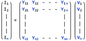
Ibus = YbusVbus
Ybus = bus admittance matrix =
Advantages of bus admittance matrix Y-bus
1) Data preparation is simple.
2) Its formation and modification is easy.
3) Since the bus admittance matrix is a sparse matrix (that is, most of its elements are zero), the Computer memory requirements are less.
For large power system, more than 90% of its of diagonal elements are 0due to the fact that in power system networks each node is connected to not more than three nodes in general and an element exists only if a transmission line links nodes p and q.
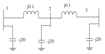
The network shown in Figure has impedance in pu as indicated, the shunt admittance is –j20 at each bus. The diagonal element of Y22

The z matrix of a two-port network is given by  The element Y22 of the corresponding Y matrix will be?
The determinant of z is


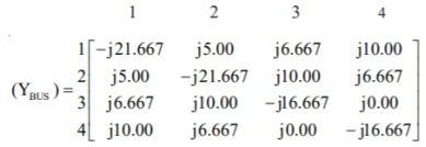
The line data of a 4-bus system is given below, obtain the YBUS.
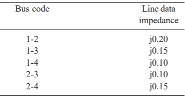
By inspection the YBUS is calculated. The values of the system are

The value of

The single line-diagram of a network is shown below. The line reactance is 0.001 pu/km and shunt capacitance is 0.0016 pu km. Assemble the bus admittance matrix neglecting the line resistance.
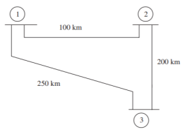
The calculate line parameters are

The pu series admittance is

Shunt admittances at the nodes are
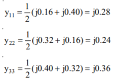
The elements of bus admittance matrix are calculated as

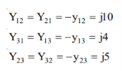
Then the bus admittance matrix is denoted by

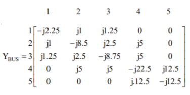
From the YBus for the given network
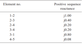
The primitive admittances are

The diagonal elements are given by
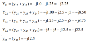
The off-diagonal elements are given by
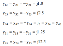
The YBUS matrix is
Find the bus admittance matrix of the following power system
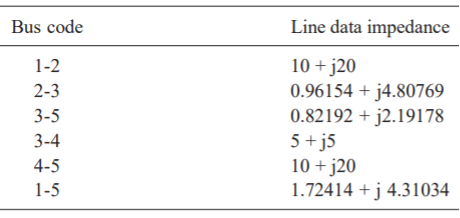
The primitive line admittances are obtained as
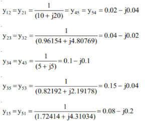
The diagonal elements are given by
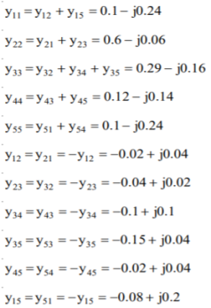
By direct inspection, the YBus is

Form YBus, YBr and ZLoop by singular transformation for the network connections given below: (2009)
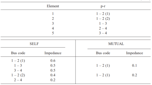
The power network is shown in Fig
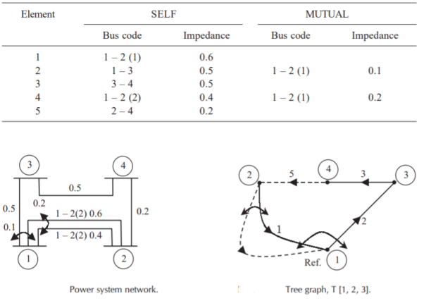
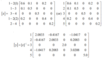
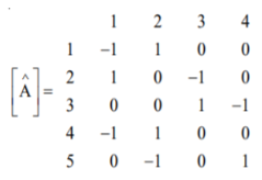
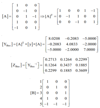
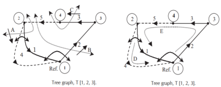
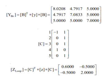
Fig shows a 3–bus power system network. The line impedances are given below:
Line (bus to bus): 1 – 2 1 – 3 2 – 3(1) 2 – 3(2)
Impedance in pu: 0.02 + j0.1 0.02 + j0.1 0.05 + j0.25 0.05 + j0.3
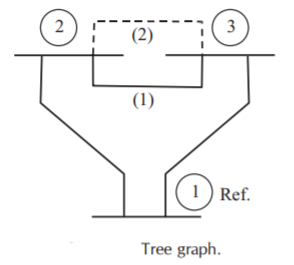
Formulate YBus for the following cases:
1. Assume that the line shown dotted between bus 2 and bus 3 i.e., line 2–3(2) is not present.
2. A new line 2–3(2) is connected and no mutual coupling with other lines.
3. When line 2–3(2) which has mutual impedance of (0.00 + j0.01) pu with line 2 – 3(1) is connected.
Case (1): By direct inspection:
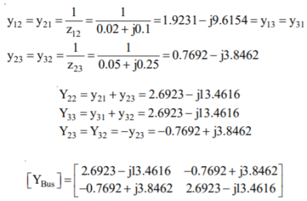
By singular transformation:
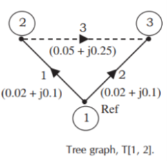
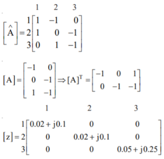
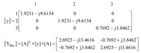
Case (2): By direct inspection:
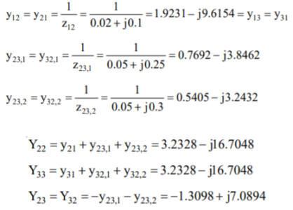

By singular transformation:
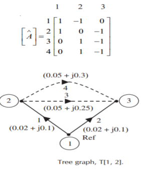

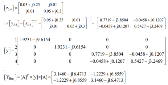
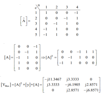
For the power system network shown in Figure, formulate YBus by singular transformation method. The self and mutual reactance in pu is indicated. Take bus (1) as reference.
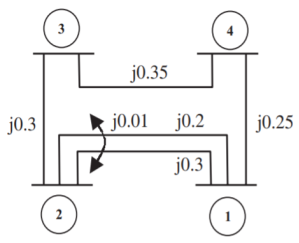
The oriented network is shown below and tree graph.
Form the YBus for the given network.
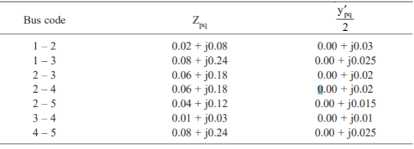
The admittance to ground is obtained by adding the admittances to ground at that bus
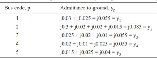

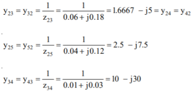
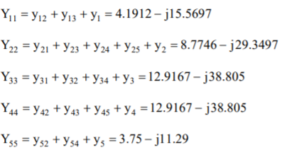
The diagonal elements are:
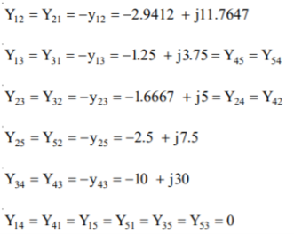
The off-diagonal elements are:
Therefore, the YBus is

State load flow equations (SLFE)
From the nodal current equations, the total current entering the ith bus of an n-bus system is given by-


The complex power injected into the ith bus is-


Separation of real and imaginary part gives


The equations 1 and 2 are called static load flow equations. Equation 1 gives n real power flow equations. Equation 2 gives n reactive power flow equations.
At each bus we have four variables Pi, Qi, Vi, resulting in total of 4n variables. In order to find solution, it is necessary to specify two variables at each bus.
Thus, number of unknown variables is reduced to 2n. Because of nonlinear nature of the equations 1 and 2, the solution of these remaining 2n variables is done by numerical methods.
The following variables are associated with each bus or node:
1) Magnitude of voltage, |Vi|
2) phase angle of the voltage, 
3) Active power, Pi
4) Reactive volt ampere, Qi
Three types of buses or nodes are identified in a power system network for load flow studies. In each bus two variables are known (specified) and 2 are to be determined. The bus classification depends upon the specified variables.
a) Spring bus or reference bus or slackbus - Voltage magnitude |Vi| and phase angle are specified for this bus. This bus is first to respond to a changing load condition.
b) Generator bus or voltage controlled bus or PV- Here |Vi| and |Pi| are specified. Often the upper and lower limits of Q are also specified. The phase angles of the voltages and the reactive powers are to be determined.
c) Load bus or P-Q bus- Here, the active power Pi and reactive voltamperes Qi are specified. Buses with neither generator nor load may be considered as load buses where P==Qi=0. If any bus in a power system network has both load and generator, then load is generally treated as negative generator.
This is an iterative technique for solving a set of simultaneous nonlinear equations in an equal number of unknowns.
Let the n equations in n unknowns are
f1 (x1,x2,……….,xn) = y1
f2 (x1,x2,……….,xn) = y2
------------------
fn (x1,x2,……….,xn) = yn
In general,
fi (x1,x2,……….,xn) = yi , 
Assume initial values of unknowns as

These values are not far from the actual solution.

i=1,2,----,n
Expanding these equations by Taylor’s series theorem, we get


It is to be noted that the partial derivatives of fi with respect to x1, x2, -----xn are evaluated at the solution estimates 
Since our initial estimate is close to the true solution, we neglect higher order terms.
From above equations,


Where I is a matrix of partial derivatives known as the Jacobian matrix or simply Jacobian of simultaneous equations.
Example-1
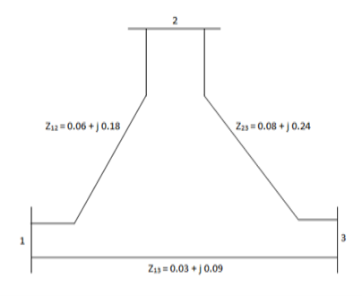
Determine Y bus for the 3 bus system. The line series impedances are as follows:
Line (bus to bus) Impedance (pu)
1-2 0.06+i0.18
1-3 0.09+i0.09
2-3 0.08+i0.24
Neglect the shunt capacitances of the lines.


Y11 = Y12+Y13= 5-i15 Y22=Y12+Y23= 2.91-i8.75 Y33= Y13+Y23 = 4.58-i13.75
Y12= -Y12 = -1.66+i5 = Y21 Y23=Y32=-Y23= -1.25+i3.75 Y31=Y13=-Y31= 3.33+i10

Example- 2
The each line has a total shunt admittance of -i5. 0 pu. Determine the modified bus admittance matrix.
Soln.
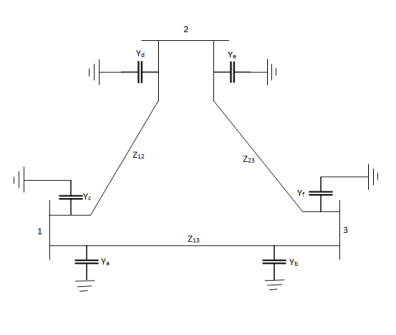
Yc+Yd=-I5.0 andYc=Yd
Ya+Yb=-i5.0 and Ya=Yb
Ye+Yf=-i5.0 and Ye=Yf
Ya = Yb = Yc = Yd = Ye = Yf = -i2.5
When we consider the effect of shunt admittances, only the diagonal elements in Ybus are modified.
Y11(new) = Y11(old) + Ya +Yc = 5-i15-i5 = 5-i20
Y22(new) = Y22(old) + Yd +Ye = 2.91- i8.75 -i5 = 2.91 -i13.5
Y33(new) = Y33(old) + Yf+Yb= 4.58 – i13.75 – i5 = 4.58 – i18.75

Example- 3
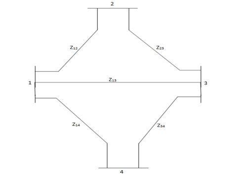
Determine Ybus for the 4-bus system shown. The line series impedances are as follows:
Line (bus to bus) Impedance (pu)
1-2 0.25+i1.0
1-3 0.20+i0.8
1-4 0.08+i1.2
2-3 0.20+i0.8
3-4 0.15+i0.6
Neglect shunt capacitances of the line.
Soln.


Example 4
Determine Ybus for the five-bus system shown in figure. Assume that the lines shown dotted are not connected and the shunt admittances at the buses and mutual couplings between the lines are neglected.
Soln.
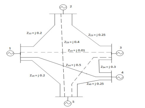


The bus admittance matrix is given by

Example 5
For given power system reactance are shown in the figure. Find the bus admittance matrix (Ybus)
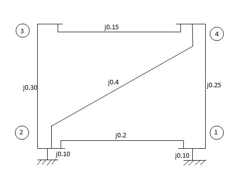
Soln.


DECOUPLED LOAD FLOW
In the NR method, the inverse of the Jacobian has to be computed at every iteration. When solving large interconnected power systems, alternative solution methods are possible, taking into account certain observations made of practical systems. These are Change in voltage magnitude |Vi| at a bus primarily affects the flow of reactive power Q in the lines and leaves the real power P unchanged. This observation implies that Qi/ |Vj| is much larger than Pi/ |Vj|. Hence, in the Jacobian, the elements of the sub-matrix N , which contains terms that are partial derivatives of real power with respect to voltage magnitudes can be made zero.
Change in voltage phase angle at a bus, primarily affects the real power flow P over the lines and the flow of Q is relatively unchanged. This observation implies that Pi/j is much larger than Qi/j. Hence, in the Jacobian the elements of the sub- matrix M , which contains terms that are partial derivatives of reactive power with respect to voltage phase angles can be made zero.
These observations reduce the NRLF linearised form of equation to
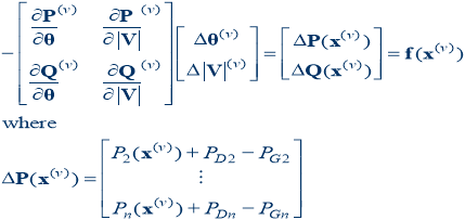
Usually the off-diagonal matrices  and
and 

Then the problem can be decoupled

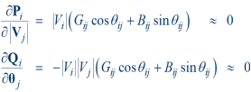
Justification for Jacobian approximation
1) Usually r<x, therefore |Gij| < |Bij|
2) Usually  ij is small so sin
  ij
ij  0
0
Therefore,
Fast Decoupled Power Flow
- By continuing with our Jacobian approximations, we can actually obtain a reasonable approximation that is independent of the voltage magnitudes/angles.
- This means the Jacobian need only be built/inverted once.
- This approach is known as the fast decoupled power flow (FDPF)
- FDPF uses the same mismatch equations as standard power flow so it should have same solution
- The FDPF is widely used, particularly when we only need an approximate solution.
The FDPF makes the following approximations
1) |Gij|=0
2) |Vi|=1
3) Sin  ij =0 and cos
  ij =1
ij =1
Then,

Where B is just the imaginary part of the Ybus = G + j B, except the slack bus row/column are omitted.
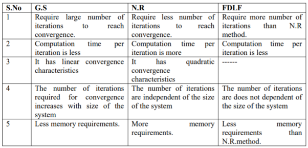
Key Takeaways
References:
- H. Hadi Sadat: Power System Analysis, Tata McGraw-Hill New Delhi.
- G. W. Stagg and El- Abiad – Computer Methods in Power System Analysis – Tata McGraw Hill, New Delhi.
- M.E. El-Hawary, Electric Power Systems: Design and Analysis, IEEE Press, New York.
- Rakash Das Begamudre, “Extra High voltage A.C. Transmission Engineering”, New age publication.
- M.A.Pai, Computer Techniques in Power System Analysis, Tata McGraw Hill Publication.
- Stevenson W.D. Elements of Power System Analysis (4th Ed.) Tata McGraw Hill, New Delhi.