Unit - 5
Unsymmetrical Fault Analysis
The majority of faults in power systems are unsymmetrical faults eg. Single line to ground faults, line to line faults, double line to ground faults, breaking of one or two conductors etc. It is necessary to calculate the fault currents in such conditions.
The information obtained is necessary for the determination of protective gear relay settings and in studies of transient stability in interconnected power system.
For manual solution of unsymmetrical faults, the symmetrical component method is simpler and enables more generality to be given to fault performance studies.
Symmetrical components
Any unbalanced three phase system of currents, voltages or other sinusoidal quantities can be resolved into three balanced system of phasors which are called symmetrical components of the original unbalanced system.
Such 3 balanced systems constitute 3 sequences networks which are solved separately on a single phase basis.
Once the problem is solved in terms of symmetrical components, it can be transferred back to the actual circuit condition by superposition or phasor additions of these quantities (currents or voltages) easily.
Symmetrical components of 3 phase systems
The symmetrical components differ in phase sequence, that is, the order in which the phase quantities go through maximum. There may be a positive phase sequence, a negative phase sequence and zero or an Uniphase sequence.
The positive phase sequence system is that system in which the phase or line currents or voltages attain maximum in the same order as those in a normal supply. Eg. Assuming the conventional counter-clockwise rotation, then the positive phase sequence phasors are shown as:
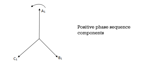
A balanced system corresponding to normal conditions contains a positive phase sequence only. Eg. Three phase fault. Positive phase sequence components are marked by subscript 1.
The three phasors are of equal magnitude spaced 120° apart and may be represented in complex form as
A1 , B1 = A1<-120˚ or A1 or a2A1
C1 = A1<120˚ or A1 or aA1
The complex no.  in above expression is called the operator of the three phase system and is denoted by letter ‘a'.
The negative phase sequence is that system in which the phasors still rotate anticlockwise but attains a maximum in reverse order. i. e. A-C-B as shown in fig.
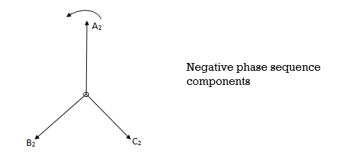
This sequence only arises under conditions of unbalance as when unsymmetrical fault occurs.
The negative phase sequence components are marked by subscript 2.
The true phasors of the negative phase sequence components are of equal magnitude and spaced 120° apart.
A2 , B2 = A2<120˚ or A2 or aA2
And C2 = A2<-120˚ or A2 or a2A2.
The zero phase sequence components is a single phase phasor system combining three equal phasors in phase as shown
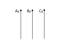
And represents the residual current or voltage present under fault conditions on a 3 phase system with a fourth wire or earth return present.
In an earth fault, positive and negative phase sequences are also present.
The zero phase sequence components are marked by subscript 0.
A0 = B0 = C0
Phase Operator
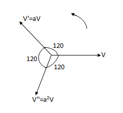
a =  = cos120 + i sin120 = -0.5 + i 0.866
It indicates that the phasor has a unit length and is oriented 120° (or 2π/3 rad) in a positive (counter clockwise) direction.
From the reference axis:
A phasor operated upon by a is not changed in magnitude but is simply rotated in position 120° in the forward direction.
For e.g.V'= aV is a phasor having the same length as the phasor V but rotated 120° forward from the phasor V.
The square of phasor a is another unit phasor oriented 120° in a negative (clockwise) direction from the reference axis or oriented 240° forward in positive direction.
a2 = ( )2 =
)2 =  =
=
a2 = -0.5-i 0.866
a3 = 1 , a4 = a , a5 = a2 and so on.
Evaluation of components or transformation matrices
Let us express phasors of an unbalanced 3 phasor system in terms of their symmetrical components.
A=A1+A2+A0
B=B1+B2+B0
C=C1+C2+C0
Expressing all the phasors of symmetrical system in the above eqns. In terms of A1, A2 and A0, we get
A=A1+A2+A0 ------------------------ (1)
B=a2A1+aA2+A0 -----------------------(2)
C=aA1+a2A2+A0 ------------------------(3)
A+B+C=A1(1+a+a2) + A2(1+a+a2) + 3A0
(1+a+a2) = 0 [ a=-0.5+i0.866=
a2=-0.5-i0.866=
Hence, A0 =  ------------------(4)
Multiplying eqn 2 by a and 3 by a2,


Adding eqn. 1,5,6


Similarly multiplying eqn. 2 by a2 and 3 by a,
a2 B=a4 A1+a3 A2+a2 A0 -----------(8)
AC=a2 A1+a3 A2+aA0 ---------(9)
Adding eqn 1,8,9


From eqns 1,2 and 3, we can write in matrix form

And from equations 4,7,10

E.g. 1 The phase voltages across a certain unbalanced 3 phase load are given as
Er = 176-i132 ,Ey = -128-i96 , EB = -160+i100.
Determine the positive, negative and zero sequence components for above voltages.
Soln. Er = 176-i132 = 220<-36.87˚ V
Ey = -128-i96 = 160<-143.13˚ V
EB = -160+i100 = 188.68 < 148˚ V
Assuming phase sequence RYB,


 -
-


 -
-


 .
.
E.g. 2 Compute symmetrical components of the 3 phase voltages.
VA = 100<0˚ , VB = 110<-100˚ , VC = 115<110˚
Soln. Positive sequence components:


Negative sequence components:


Zero sequence components:


E.g. 3 A single phase load of 100kVA is connected across lines bc of a 3- phase supply of 3.3 kV
Determine symmetrical components of line current.
Soln.
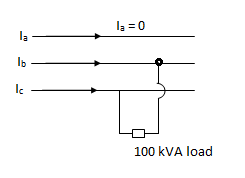

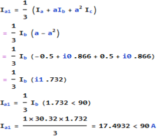
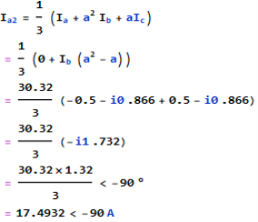
Ic = -Ib = -30.30A
Positive sequence component,
Negative sequence component-
Zero sequence component-

Three phase power in terms of symmetrical components
The power consumed in a 3 phase circuit can be determined directly from the symmetrical components provided the currents and voltages are given.
Total complex power in 3 phase ckt. Is given as
S=P+iQ = VpT I*p = Va Ia* + Vb Ib* + Vc Ic*
Where Va, Vb and Vc are the voltages to neutral and Ia, Ib, Icare the currents flowing into the circuit in 3 lines, the 3 phase circuits are assumed to be star connected. The subscript T stands for transposition.


The dot product of two phasors does not change when both are rotated through the same angle.


Or 
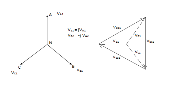
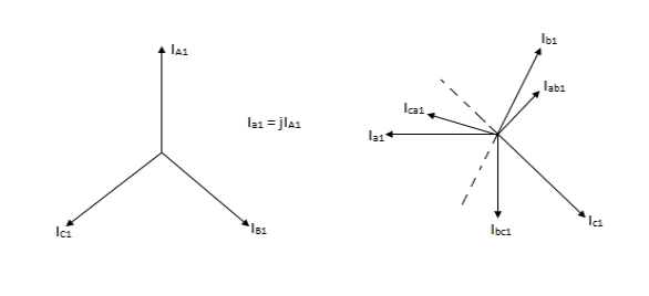
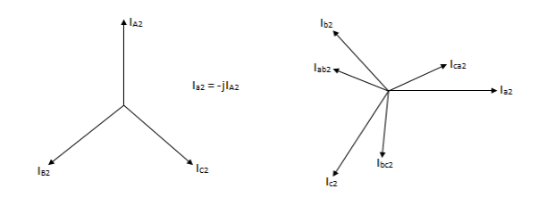
Phase shift in star delta transformers
The angular difference between phases representing the voltages induced between high voltage and low voltage terminals having some marking letters and the corresponding neutral points (real or imaginary) expressed with reference to High Voltage side is known as phase displacement (or shift) of the transformer.
In a star star or delta delta three phase transformer there is no phase shift between the corresponding voltages of any Phase to neutral on either side.
However, Delta connected winding is desirable in many Power Transformers for reasons of harmonic elimination.
So that most of the Power Transformers are either star delta or Delta star connected. Inn such Transformers, even under normal operating condition, the phase to phase voltages and phase to neutral voltage sources of High Voltage side are displaced from the corresponding voltages of low voltage side.
The phase shift of 30° comes in group of 4 and that of – 30° comes in group of 3.
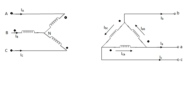
Positive sequence voltages in a ʎ- ∆ transformer.
Positive sequence currents in a ʎ- ∆transformer.
Negative sequence currents in a ʎ- ∆transformer.
Physical significance of sequence components
If a set of positive sequence voltages is applied to the stator winding of a three phase induction motor, a magnetic field revolving in a certain direction will be developed.
Now in the two of the three phases supply leads to the stator winding are interchanged, the direction of revolution of the field developed would be reversed.
Thus the field developed by the set of negative sequence voltages will rotate in a direction opposite to that of the field developed by the set of negative sequence voltages will rotate in a direction opposite to that of the field developed by the set of positive sequence voltages.
The zero sequence voltages are single phase voltages and therefore they give rise to an alternating field in space.
The positive and the negative sequence sets are balanced ones. i. e. If only positive and / or negative sequence currents are flowing, the phase sum of each will be zero and there will be no Residual current.
However, the zero sequence components of currents in the three phases are equal in magnitude and are in phase.
In case of an earth fault, the positive and the negative sequence current balance between themselves but the zero sequence currents flow through the grounds and ground wire.
Sequence impedances and Sequence network
Impedance of the network offered to the flow of positive sequence current is called positive sequence impedance. Similarly, if only negative sequence current flow, the impedance of the network offered to this current is called the negative sequence impedances. Also, the impedance offered to zero sequence current is called as zero sequence impedance of the network.
If Za, Zb, Zcare the impedances of the load between phases a, b and c to neutral n, then sequence impedance is are given as
Positive sequence impedance, Z1 = 1/3 (Za + aZb + a2Zc)
Negative sequence impedance, Z2 = 1/3 (Za + a2Zb + aZc)
Zero sequence impedance, Z0 = 1/3 (Za + Zb + Zc)
For a 3 phase, symmetrical static circuit without internal voltages like Transformers and transmission lines, the impedances offered to the currents of any sequence are the same in the three phases. Also, the currents of a particular sequence will cause voltage drop of the same sequence or a voltage of a particular sequence will give rise to current of the same sequence only, which means that there is no mutual coupling between the sequence networks.
The single phase equivalent circuit composed of the impedance to current of any one sequence only is called the sequence network for that particular sequence. Hence, we have positive, negative and zero sequence networks carrying currents Ia1, Ia2 and Ia0 are then interconnected in different ways to represent different unbalanced fault conditions.
The sequence current and voltages during the fault are then calculated, from which actual fault currents and voltages can be determined.
Positive sequence network is considered in the analysis of symmetrical faults.
Negative sequence network differs from positive sequence network in following points:
- Normally there are no negative sequence EMF sources.
- Negative sequence impedances of rotating machines are generally different from their positive sequence impedances.
Zero sequence network will be free of internal voltages, the flow of current being caused by the voltage at the fault point.
Sequence impedances and networks of synchronous alternator
An unloaded synchronous machine grounded through a reactor of Impedance Zn is shown in figure. Ea, Eb and Ec are the induced EMFs in the three phases. When an unsymmetrical fault occurs on the machine terminals, unbalanced currents Ia, Ib and Ic flow in the lines. If the fault involves ground, a current inflows to neutral from ground wire reactor Zn.
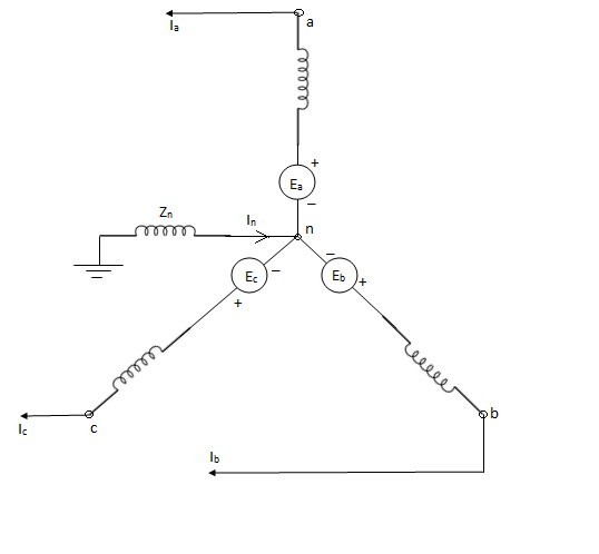
Positive sequence impedance and network- since a synchronous machine is designed with symmetrical windings, it has induced EMF of positive sequence only. Ie. No negative or zero sequence voltages are induced in it.
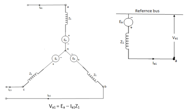
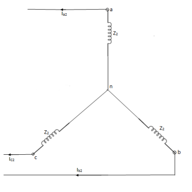
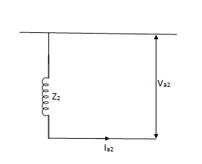
Negative sequence impedance and network- synchronous machine does not generate any negative sequence voltage. Flow of negative sequence currents in the stator winding produces an nnf rotating synchronously in a direction opposite to that of rotor.
Thus, the negative sequence field rotates at a speed twice the synchronous speed with respect to rotor.

Va1 = Ea – Ia1Z1
Va2 = - Ia2Z2
Zero sequence impedance and network-
No zero sequence voltage is induced in synchronous machine. The flow of zero sequence currents in the stator windings produces twice mmfs which are in time phase but are distributed in space by 120°.
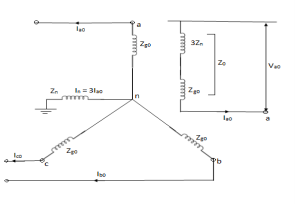
Z0 = 3Zn + Zg0
Va0 = -Ia0Z0 = -Ia0(Zg0 + 3Zn)
Sequence Impedances and Networks of transformers
The positive sequence series impedance of transformer is equal to its leakage reactance (the resistance of the winding is usually small in comparison to the leakage reactance). Transformer being a static device, the positive and negative sequence impedances are identical.
Z1 = Z2 =Zleakage
The zero sequence current can flow through the winding connected in star only if the star point is grounded.
Moreover, the zero sequence currents cannot flow through the winding if the star point is isolated.
No zero sequence current can flow in the lines connected to a delta connected winding as no return part is available for this zero sequence currents. Zero sequence current can however flow through the Delta connected windings themselves if any zero sequence voltages are induced in delta.
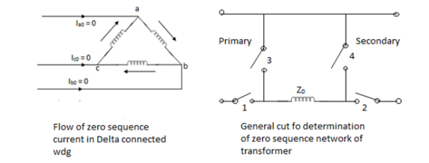
Z0 is the Zero sequence impedance of Transformer. The series switch of a particular side is closed if it is star grounded and the shunt switch is closed if that side is delta.
S.No. | CONNECTION DIAGRAM | ZERO SEQ. CIRCUIT | REMARK |
1. | Star-star with isolated neutral 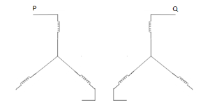 |  | Since neutrals of both primary and secondary windings are isolated, zero sequence currents cannot flow. |
2. | Star-star transformer with any one neutral grounded. 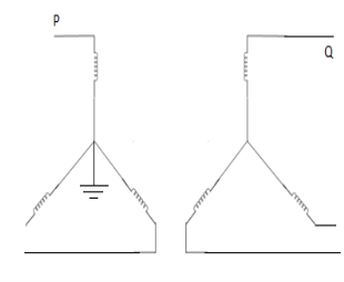 |  | If any one of the neutrals of a star-star transformer is ungrounded, zero seq. Currents cannot flow in the ungrounded star and consequently these currents can’t flow. Switches 2,3,4 are open. |
3. | Star-star with both neutral grounded 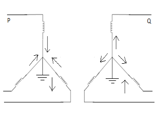 |  | Since both neutrals are grounded, path exists for zero seq. Currents in both wdg. 1 and 2 are closed, 3 and 4 are open. |
4. | Star-delta with grounded Y neutral 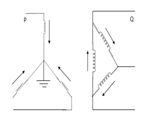 |  | In this arrangement, the neutral of star side is grounded, so zero sequence currents can flow in star and balancing zero seq. Currents can flow in delta. No zero sequence currents can flow in delta side. |
5. | Star-delta with isolated star 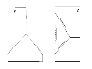 |  | In this arrangement, no zero sequence currents can flow in the transformer wdgs. |
6. | Delta-delta 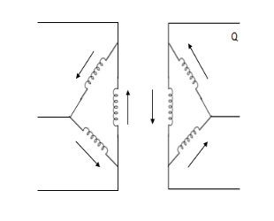 |  | Delta ckt. Does not provide return path, zero seq. Currents cannot flow in or out of delta-delta transformer. However zero sequence currents can circulate in delta wdg. |
7. | Star-star with any neutral grounded and tertiary 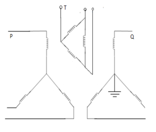 | 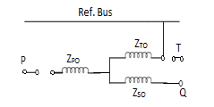 | Here, tertiary winding provides path for zero-sequence currents. |
Fault analysis of unloaded synchronous generator
a) Three phase fault- symmetrical fault (L-L-L or L-L-L-G)
An unloaded star connected alternator is shorted by a three phase fault. The generator neutral is earthed through an impedance.
The generator terminals being shorted Va, Vb, Vcare equal to zero and the sum of the currents Ia, Ib and Ic is zero.
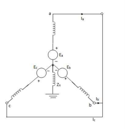


Ea – Ia1Z1 = 0
Ia1 = Ea / Z1
This means only positive sequence network is present.
b) Single line to ground fault-
An unloaded alternator with its phase grounded. The alternator neutral is assumed to be grounded through an impedance Zn. Let the fault impedance Zf.
Under fault condition,
Ib=0, Ic=0 and Va= Ia Zf
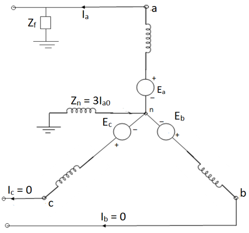

Ia0 = Ia1 = Ia2 =(1/3) Ia ---------(1)
Va = Va0 + Va1 + Va2 ----------(2)
=Ia Zf
=3Ia1 Zf
Thus, we can write as,
Va0=-Ia0Z0=-Ia1Z0 (from sequence components of synchronous machines)
Va1=Ea- Ia1Z1 and
Va2 =-Ia2Z2 = -Ia1 Z2 ----------------(3)
From 2 and 3,
-Ia1Z0+Ea – Ia1Z1 – Ia1Z2 =Ia. Zf
Ea – Ia1(Z0+Z1+Z2)=3Ia1 Zf

The fault current If = Ia = 3Ia1
If = Ia =
Also, Z0 = 3Zn +Zg0
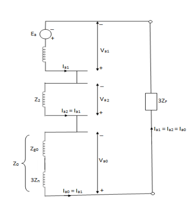
In case of generator with isolated neutral, the zero sequence impedance Z0 becomes infinite and

Ia1 = Ia2 = Ia0 = 0
Thus, fault current = 0
c) Line to line fault-
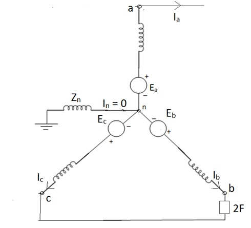
An unloaded alternator with line to line fault on its phases b and c. The alternator neutral is assumed to be grounded through an impedance Zn. The phase a is open. Let the fault impedance be Zf.
Under fault condition, the currents and voltages are given as:
Ia =0 , Ib = -Ic
Vb – Vc =Ib Zf
Or Vc =Vb -Ib Zf
Symmetrical components of currents and voltages are given as:


 a1 = -Ia2
 a0 = 0
Similarly,


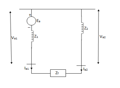
3(Va1 – Va2) = (a-a2) Ib Zf = Ib Zf
Ib Zf
Ib = (a2 – a)Ia1 = - Ia1
Ia1
Va1 – Va2 = 

d) Double line to ground (L-L-G) fault-
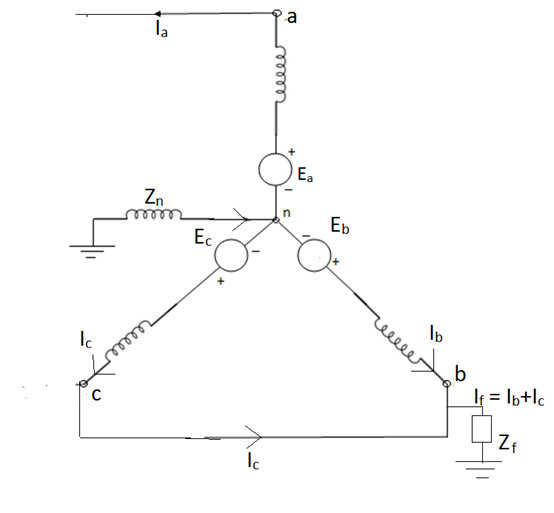
The alternator neutral is assumed to be grounded through an impedance Zn.
Under fault condition,
Ia = 0 If =Ib + Ic
Vb = Vc = If Zf = (Ib + Ic)Zf = 3Ia0 Zf


 2 = -1 )


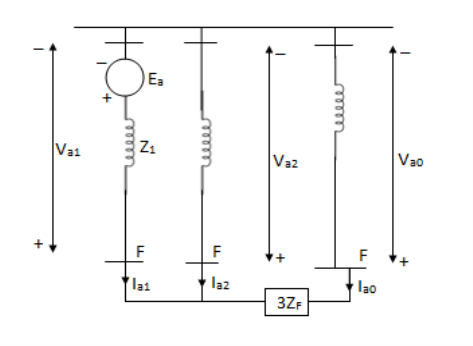

 of direct short cut Zf = 0

Example-
The line to neutral voltages in a 3 phase system are Van= 200<0°, Vbn= 600<100°, Vcn= 400<270° Find the symmetrical components of the voltages.
Soln.


Example-
A delta connected load is connected to 3 phase supply, one line of supply is open. The current in other two lines is 20<0° A and 20<180° A. Find symmetrical components of the line currents.
Soln. 
Zero sequence components-


Positive sequence components-


Negative sequence components-


Example-
The zero and positive sequence component of R-phase are as under Vr0 = 0.5 – i0.866 pu and
Vr1 = 2<0 pu. If the phase voltage of R-phase is Vr= 3<0°pu, find the negative sequence component of R phase and phase voltages Vy and VB assuming phase sequence as RYB.
Soln.


References:
- H. Hadi Sadat: Power System Analysis, Tata McGraw-Hill New Delhi.
- G. W. Stagg and El- Abiad – Computer Methods in Power System Analysis – Tata McGraw Hill, New Delhi.
- M.E. El-Hawary, Electric Power Systems: Design and Analysis, IEEE Press, New York.
- Rakash Das Begamudre, “Extra High voltage A.C. Transmission Engineering”, New age publication.
- M.A.Pai, Computer Techniques in Power System Analysis, Tata McGraw Hill Publication.
- Stevenson W.D. Elements of Power System Analysis (4th Ed.) Tata McGraw Hill, New Delhi.