Unit - 6
HVDC Transmission
INTRODUCTION
Comparison of ac and dc transmission
a) Economics of transmission
The cost of a transmission line includes the investment and operational costs. The investment includes cost of Right of way, transmission towers, conductors, insulators and terminal equipment. The operational costs include mainly the cost of losses.
For DC line at given power level requires less Tow, simpler and cheaper towers and reduced conductor and insulator costs as it has only two conductors.
The power losses are also reduced with DC as there are only two conductors (about 67% of that for AC with some current carrying capacity of conductors).
The absence of skin effect with DC is also beneficial in reducing power losses marginally.
The corona effectis also less significant on DC conductors than for AC and this also leads to the choice of economic size of conductors with DC transmission.
DC lines don’t require compensation but the terminal equipment costs are increased due to the presence of converters and filters.
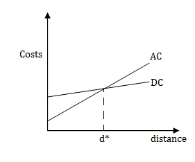
Where d* - break even distance
b) Technical performance
Stability limits-The power transfer in AC lines is dependent on the angle difference between the voltage phasors at the two ends. For a given power level, this angle increases with distance.
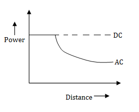
Voltage control - The reactive power requirements increases with the increase in the line lengths for AC transmission.
c) Reliability
The reliability of DC Transmission Systems is quite good and comparable to that of AC systems as both energy availability and transient stability of existing DC systems with thyristor valves is 95% or more.
Energy availability = 
Where equivalent outage time is the product of the actual outage time and fraction of system capacity loss due to outage.
Transient reliability= 
Transient reliability is a factor specifying the performance of HVDC systems during recordable faults on the associated AC systems.
Description of DC transmission system
Types of DC links- The DC links are classified into three types –
a) Monopolar link - It has one conductor usually of negative polarity and uses ground or sea return. Sometimes metallic return is also used.

b) Bipolar- It has two conductors one positive and other negative. Each terminal has two sets of converter of identical ratings in series on the DC side. The junction between the two sets of converters is grounded at one or both ends. Normally both poles operate at equal currents and hence there is Zero ground current flowing under these conditions.
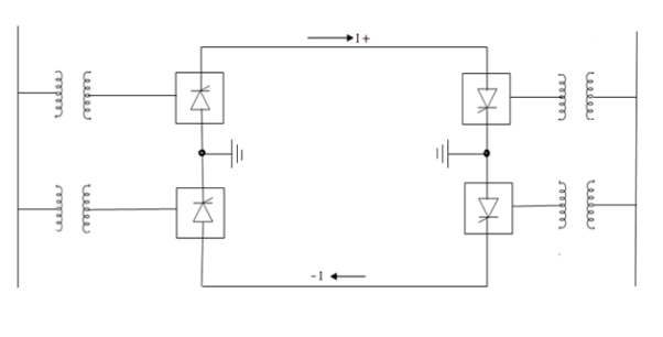
c) Homopolar - It has two or more conductors all having the same polarity, usually negative and always operated with ground or metallic return.
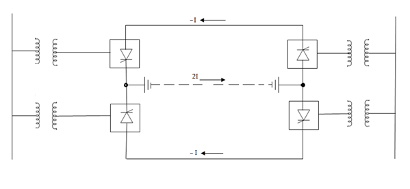
Because of the desirability of operating a DC link without ground return, bipolar links are commonly used. As the Corona effects in a DC line are substantially less with negative polarity of the conductor as compared to the positive polarity.
Converter Station- Here the conversions rom AC to DC (rectifier Station) and from DC to AC (inverter station) are performed. Typically, two 12 pulse converters units per pole are used.
a) Converter unit - This usually consists of two three phase converter bridges connected in series to form 12 pulse converters.
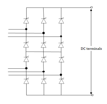
b) Converter Transformer- The converter transformer can have different configurations:
i) 3 phase two winding
Ii) Single phase 3 winding
Iii) single phase 2 winding
The valve side windings are connected in Star and Delta with neutral point ungrounded. On the AC side, the Transformers are connected in parallel with neutral grounded.
c) Filters- AC filters, DC filters and high frequency (RF/PLC) filters.
d) Reactive Power source- Converter stations require reactive power supply that is dependent on the active power loading. (about 50% to 60% of the active power). Part of this reactive power requirement is provided by AC filters. In addition, shunt capacitors, synchronous condensors and static vary systems are used.
e) Smoothing reactor- A sufficiently large series reactor is used on DC side to smooth DC current and also for protection.
f) DC switchgear- DC breakers or metallic return transfer breakers (MRTB) are used, if required for interruption of rated load currents.
Principles of link control
The control of power in a DC link can be achieved through the control of current or voltage.
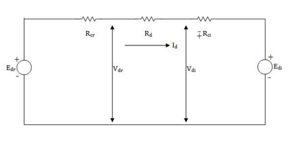
Steady State equivalent circuit of a 2 terminal DC link

Schematic of a DC link showing transformer ratios.
The series connected bridges in both poles of converter stations are identical and have the same delay angles. Also, the number of series connected bridges (nb) in both stations are the same. The Voltage sources Edr and Edi are defined by
Edr = 
Edi = 
Where Evr and Evi are the line to line voltages in the valve side windings of the rectifier and inverter transformer respectively. These voltages can be obtained as:


WhereEr and Ei are the AC(line to line) voltages of the converter buses on the rectifier and the inverter side.
Tr and Ti are the off-nominal tap ratios on the rectifier and inverter side.
Edr = (ArEr / Tr) 
Edi = (AiEi / Ti)
Where  i is the extinction angle.
The steady state current Id in the dc link is obtained as:
Id = 
-veRci if the extinction angle is constant.
Id = 
As the denominator is small, even small changes in the magnitudes Er or Ei can result in large changes in the DC current if the control variables are held constant.
Also, current and power can be controlled by changing Transformers tapsTr and Ti. This can be achieved only by slow control of mechanical switches.
It is desirable to achieve current control at the rectifier stations under normal conditions.
1) The increase of power in the link is achieved by reducing  which improves the power factor at the rectifier for higher loading and minimises the reactive power consumptions.
2) The inverter can now be operated at minimum𝞬 thereby minimising the reactive power consumption at the inverter also.
This implies that current controller must be also provided at the inverter in addition to the CEA controllers. A smooth transition from CEA to CC takes place whenever the link current starts falling. To avoid clash of two current controllers, the current reference at the inverter is kept below that at the rectifier by an amount called the current margin. This is typically about 10% of the rated current.
The power reversal in the link can take place by the reversal of the DC voltage. This is easily done by increasing the delay angle at the station initially operating as the rectifier while reducing the delay angle at the station initially operating as the inverter. Thus, it is necessary to provide both CEA and CC controllers at both terminals.
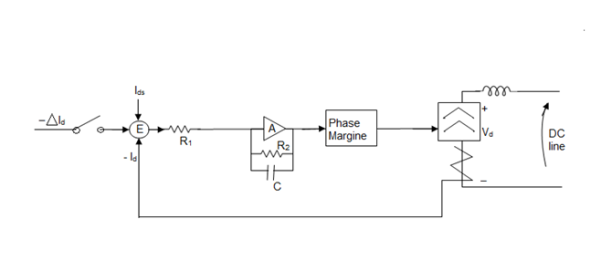
Constant current control-
The constant current consists of –
i) Measurement of direct current.
Ii) Comparison of Id with the set values Ids.
Iii) Amplification of the difference Ids – Id called the error.
Iv) Application of the output signal of the amplifier to a phase shift circuit that alters the ignition angle  of the valves in the proper direction for reducing the error.
If the measured current in a rectifier is less than the set current,  must be decreased in order to increase cos
 and thus raise the internal voltage of the rectifier Vd0cos
 . The difference between the internal voltages of the rectifier and the inverter is thereby increased and direct current is increased proportionally.
If the measured current exceeds the set current,  must increase instead of decreasing.
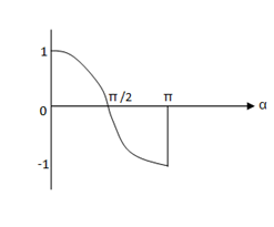
The curve ofcos versus
  in the range from 0 to π is monotonic. Any where in this range, a decrease of
  increases the algebraic internal voltageVd0cos
 .
.
Constant-Minimum ignition angle control-
If the constant minimum ignition delay angle 0is to be zero, no special provision need to be made for it because 0 is inherently the minimum possible delay. But for some valves, by observing the voltage across each valve is measured and if it is less than a specified value, then the constant current control prevent it from ignition. Since the purpose of the delay is to ensure the certain voltage across the valve before igniting it, the method is logical although it allows some variation in to opposite changes in magnitude Vm of alternating voltage.
Converter control characteristics-
The DC voltage at the station II versus DC current characteristic is divided into 3 parts.
Station I Station II Type
Ab hg minimum 
Bc gf constant current
Cd fe minimum 𝞬
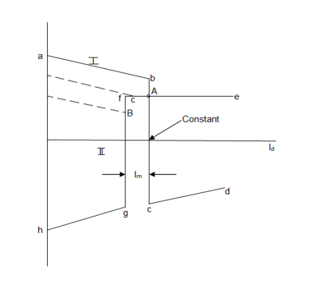
The intersection of the two characteristics (point A) determines the mode of operation. Station I operating as rectifier with constant current control and Station II operating at constant extinction angle.
Dissipation capabilities which vary with the location of the arresters.
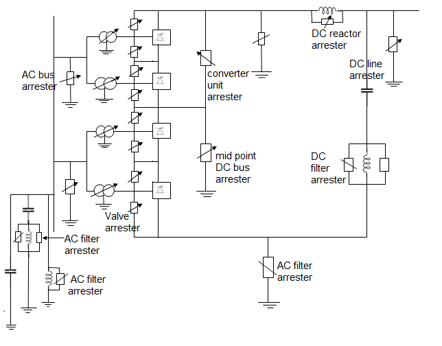
Multiterminal HVDC system
There are 3 specific areas of applications for MTDC systems.
i) Bulk power transmission from several remote generating stations to several load centres.
Here a system of two generating stations and two loads is shown below.
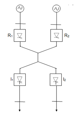
This is a radial system with two rectifiers and two inverters.
For ensuring the same level of flexibility in energy exchange, three two terminal DC links will be required in addition to a link connecting the two receiving systems which could be AC or DC.
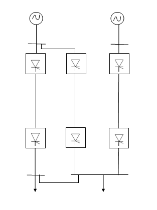
This could result in extra costs for the convertor stations, lines and additional power losses in increased number of conversions.
Ii) Asynchronous interconnection between adjacent power systems.
Iii) Reinforcing of an AC network which is heavily loaded.
Consider an urban power system which is fed by a distant power station. It would be advantageous to arrrange the power injection at more than one point so that the underlying AC network is not overloaded.
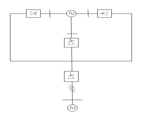
Types of MTDC systems-
1) Series MTDC system- This is a natural extension of the two terminal system which is a series connected system. A three terminal MTDC system with a monopolar arrangement is shown as:
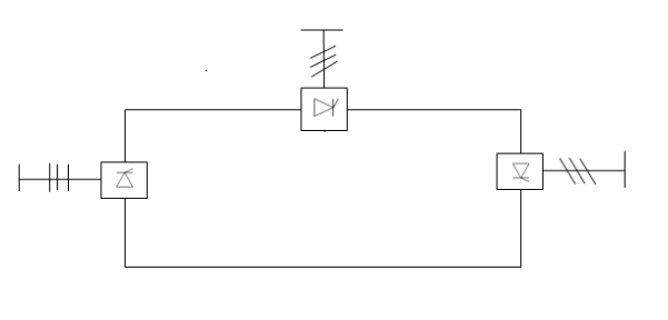
In one converter station would require either the disconnection of a bridge in all the stations or disconnection of the affected station.
Comparison of series and parallel MTDC system
i) High speed reversal of power is possible in series systems without mechanical switching. This is not possible in parallel systems.
Ii) The valve voltage rating in a series system is related to the power rating while the current rating in a parallel connected system is related to the power.
Iii) There are increased losses in the line and valves in series system in comparison to parallel systems.
Iv) Insulation coordination is a problem in series system as the voltage along the line varies.
v) The permanent fault in a line section would lead to complete shutdown in a series connected system while it would lead to only the shutdown of a converter station connected to the line section in a radial MTDC system.
Vi) The reduction in AC voltages and commutation failures in an inverter can lead to overloading of converters as current is transferred from other terminals in a parallel system.
Vii) The control and protection philosophy in a series MTDC system is a natural extension of that in a two terminals system. However, extension to parallel systems is not straight forward. It requires more communication system and also there are problems associated from commutation failures with parallel systems.
The series connection is appropriate for taps of rating less than 20% of the major inverter terminal, while parallel connection is more versatile and is expected to be used in AC systems.
Components of HVDC transmission system
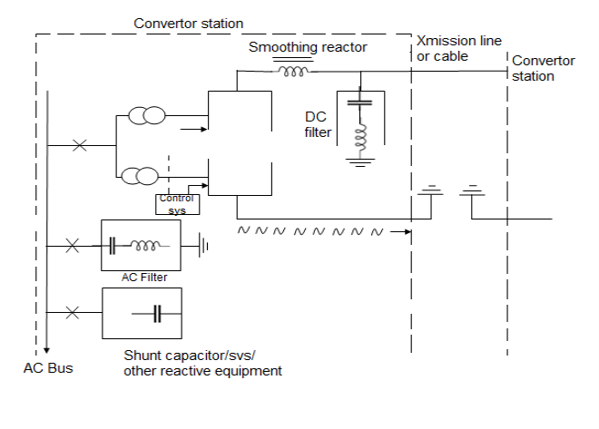
- Converter transformer- Transformers provide a suitable voltage ratio to achieve the desired direct voltage and Galvanic separation of the AC and DC systems.
The valve side windings are connected in Star and Delta with neutral point undergrounded. The leakage reaction of the transformer is chosen to limit the circuit current through any valve.
- Filters- 3 types of filters are used-
a) AC filter- they are used to provide low impedance shunt path for AC harmonic current.
b) AC filter- These are also same as AC filter used for filtering DC harmonics.
c) High frequency filters - these are connected between the converter x’mer of station AC bus to suppress any high frequency current.
Smoothing Reactor
It reduces the harmonic current in the DC line possible transient overcurrent.
It serves the following-
i) Smoothen the ripple in the direct current
Ii) Decreases the harmonic voltage of current in DC line.
Iii) Limit the fault current in DC line.
Types of DC links-
1) Mono polar link

It has only one energized conductor normally of negative polarity and uses ground or sea water as a return path.
It may be noted that earth as much lower resistance to DC as compared to AC.
Negative polarity is preferred on overhead lines due to less radio interference.
2) Bipolar link
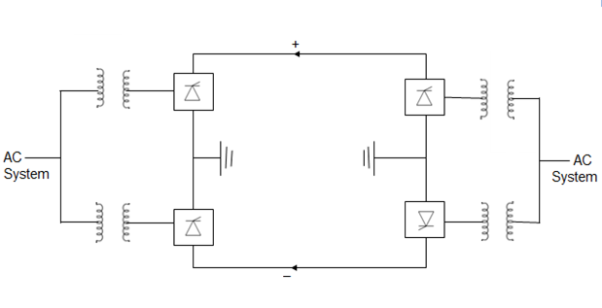
This link has two conductors positive and negative at the same magnitude 650 KV. At each terminal two conductors of equal rated voltage are connected in series on the DC side.
The neutral points are grounded at one or both ends. If both neutrals are grounded, two poles operate independently.
If current in two conductors are equal the ground current is zero.
If one conductor has a fault, the Other conductor along with ground return can supply half the rated load.
A bipolar line can be operated as monopolar line in an emergency.
3) Homopolar link
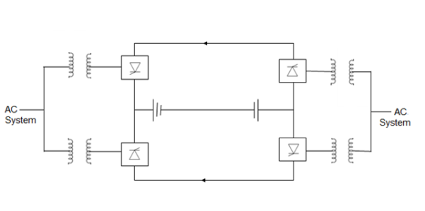
In homo polar link two or more conductors all having same polarity (usually negative) as Corona loss of radio interference reduced and is always operate with ground as the return.
If one of the conductors develops a fault the converter equipment can be reconnect so that healthy conductor can supply more than 50% of the rated power.
A 2 conductor DC line is more reliable than 3 conductor AC line because at the event of fault on one conductor. The other conductor can continue to operate with ground return during the fault current. Therefore, DC is reliable.
If a homo polar DC line is compared with double circuit 3 AC line, the DC line cost would be about 45% less than the AC line.
Components of HVDC Transmission
Converter unit- The conversion from AC to DC and vice versa is done in converter station using 3 bridge converter
IN HVDC k1 mission, 12 pulse bridge converter is used, such a converter is obtained by connecting to two 6 pulse bridge in series.
The two series connected 6 pulse bridged identical except that AC supply voltage to the two bridge are shifted in phase by 30°. This phase shift is usually obtained by supplying 6 pulse Bridge by λ-λ by 3 k,mer.
Que. Technical and economic advantage of HVDC over HYDC
- DC line can carry as much power with two conductors as AC line with three conductors of the same size.
- Lessor number of conductor and insulator and therefore reduced conductor and insulator cost associated with transmission.
- When the Phase to phase clearance and lesser phase to ground clearance.
- Lighter and cheaper tower in case of HVDC.
- Less right of way(ROW) requirement in case of HYDC.
- Power losses are also reduced with DC as there are only two conductors (about 67%) as that of AC with same current capacity conductors.
- Absence of skin effect in case of DC is also beneficial in reducing power loss marginally.
- The dielectric losses in case of DC power cables are small.
- Lesser Corona loss of reduced radio and telephonic interference since the corona effect are less the choice of economical size of conductor with HVDC is possible.
- DC line don’t require compensation but the terminal equipment cost is increased due to presence of converters.
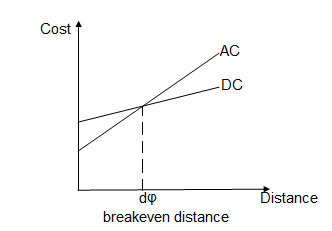
- AC tends to be more economical than DC for distance less than breakeven distance and costlier for longer distance.
- The breakeven distance can vary from 500 to 800 km.
Advantages-
(i) Corona loss, radio interference and audible emission are less
(ii) No reactive compensation of DC lines required.
(iii) Each conductor can be operated as an independent circuit.
(iv) There is easy reversibility and controllability of power flow through DC link.
(v) No charging current and skin effect.
(i) It is possible to bring more power into an AC system via a DC link without rising a fault level of CB ratings.
(ii) DC tables can be worked at Higher voltage gradient.
(iii) voltage regulation problem is less for DC
(iv) line losses are smaller
(v) It can interconnect two rigid systems operating at different frequencies
(vi) Power losses are also reduced with DC as there are only two conductors (about 67% that of AC with same current capacity)
Disadvantages–
(i) Harmonics are generated which require filters.
(ii) more frequent cleaning of insulators is required. Pollution affect DC more than AC.
(iii) There is no DC device which can perform excellent switching operation and ensure protection.
(iv) converters don't have overload capability
(v) converters require considerable reactive power
(vi) No reactive power can be transmitted over DC link.
(vii) Installation of converters are complicated and DC switchgearis expensive.
Limitations-
(i) Circuit breaker - cost of DC CBs are too high.
(ii) Transformers - doesn’t have x'mer to step up or step down the DC voltage levels.
(iii) Generation of harmonics - Both AC and DC harmonics generator. AC and DC filters are required to minimise harmonics thus cost increases.
(iv) Cooling of HVDC substation- effective cooling system is required to dissipate the heat.
(v) System control - the system control is quite complex.
Applications-
a) Interconnection of system of the same frequency through zero length dc-link (back to back connection)
b) Interconnection between power systems
c) HVDC are used to evacuate power from the remote super power station to the load Centre situated several hundred kilometres away.
d) High power submarine distribution system feeders.
e) stabilizing AC system by modulating DC power flow.
HVAC | HVDC |
It stands for High Voltage Alternating Current. | It stands for High Voltage Direct Current. |
It uses a transformer for voltage conversion. | It uses solid-state semiconductor based converters for voltage conversion. |
The HVAC voltage conversion is simple & inexpensive. | The HVDC voltage conversion is complex & expensive. |
HVAC transmission requires a minimum of three conductors. | The HVDC requires only two conductors in bipolar & one conductor in monopolar transmission. |
The HVAC transmission is used for less than 600 Km distance. | The HVDC transmission is used for transmitting bulk power more than 600Km distance. |
It offers better flexibility allowing multiple tappings in the pathway. | It does not offer flexibility & transmit power from point to point. |
The effective power transmission capability is affected by reactive power losses. | There are no reactive power losses in HVDC transmission. |
The conductors are affected by corona losses. | The corona losses in HVDC are reduced by a factor of approximately 3. |
It requires a large diameter cable due to skin effect. | The current stays uniform in cable thus it can use comparatively smaller diameter cable. |
It wastes almost 30% of conductor capacity due to AC peak ratings while delivering average power. | It utilizes full conductor capacity due to the DC peak & average being the same value. |
The HVAC has a broader right-of-way. | The HVDC has a narrower right-of-way. |
The HVAC transmission requires tall sized towers. | The HVDC transmission requires a smaller tower. |
It is not preferred for submarine or underwater power transmission due to the stray capacitance of the cables. | The HVDC is preferred & used for submarine power transmission offshore. |
HVAC does not offer controllability. | It offers great controllability over the power flow, frequency control & dampening of power swings. |
The AC generates interference in the nearby communication lines. | The direct current does not generate any interference. |
The line arc may extinguish because of the voltage zero-crossing. | The arc will never get a chance to extinguish unless the power source is tripped. |
The HVAC circuit breakers are simple & cheaper because the arc will self-extinguish. | The HVDC circuit breakers are expensive & have complex design circuit to force the current to zero. |
The HVAC is best suitable for overhead power transmission at distances below 600 km which is economical. | The HVDC is used for long-distance bulk power transmission including underwater as well as the asynchronous interconnection between AC grids. |
Constant current control method-
It performs the following functions and operations-
- Measures the system current Id.
- Compare it with reference current Id.
- Amplifies the error signal.
- The o/p error signal controls
 in case of rectifier and ∂ in case of inverter in proper direction to reduce the error.
 - If the measured current is more then the reference
 may be increased. In case of rectifier to decrease the open circuit voltage of the rectifier.
 - The difference between the open circuit voltage of the rectifier and the inverter is decreased and the current is decreased proportionally.
- However in case of an inverter if the measured current is more than the reference current the open circuit voltage of the inverter must be increased instead of being decreased.
- If we consider inverter voltage to be negative which is usual, the same converter sometimes rectifiers at other inverter.
- The algebraic value of inverter voltage must be decreased as a rectifier and to accomplish this
 must be increased.
Constant ignition angle control method
The voltage Vdi from the rectifier circuit is given by
Vdi = Vcrcos -Id(Rcr +RL) and from inverter circuit
Vdi = Vcicos +IdRci
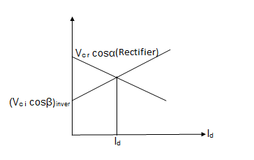
In order that current Id flows OCV of rectifier must be higher than OCV of inverter. The point of intersection (Id, Vdi) of these characteristic gives the operating point.
The inverter operation under such condition constant
a) Excitation angle may be larger.
b) Vdg dip in AC side.
c) Suppose that Normal current Id is flowing and that is so adjust that  as ahown in fig.
If now voltage on the AC side experience symmetrical dip assuming that the current does not change substantially, same current induces at reduce voltage this requires that the shaded areas.
A Stunt fault will not only reduce the commutating voltage but also increases or decreases the available commutation angle as shown in figure.
In case of dip in voltage on AC side, the rate of change of current maybe very large. That’s the fact that the large smoothing reactor are in the system.
This controller consists of separate computer for each group of thyristor connected to the same phase.
Each computer continuously computes and providing the signal for firing of thyristor.
The computer monitors the following quantities:
1) amplitude of commutative voltage
2) Phase of commutating voltage
3) magnitude of direct current.
Extinction Angle Control
The current controller is invariably of feedback type which is of PI type The extinction angle controller can be of predictive type or feedback type with IPC control. The predictive controller is considered to be less prone to commutation failure and was used in early schemes. The feedback control with PFC type of Equidistant Pulse Control overcomes the problems associated with IPC. The extinction angle, as opposed to current, is a discrete variable and it was felt the feedback control of gamma is slower than the predictive type. The firing pulse generation is based on the following equation
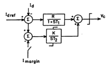

Where ecj is the commutation voltage across valve j and tn is the instant of its firing. In general, the prediction of firing angle is based on the equation
Βj = γref + µj
Where µj is the overlap angle of valve j, which is to be predicted based on the current knowledge of the commutation voltage and DC current. Under large disturbances such as a sudden dip in the AC voltage, signals derived from the derivative of voltage or DC current aid the advancing of delay angle for fast recovery from commutation failures.
Sr. No | System/Project | Year of Commissioned | Power Rating | Voltage |
1 | National HVDC project-stage-I | 1989 | 100 MW | 100 kV |
2 | National HVDC project-stage-II | 1999 | 200 MW | 200 kV |
3 | Rihand-Delhi | 1990 | 1500 MW |  |
4 | Chandrapur- Padghe | 1999 | 1500 MW |  |
The basic element in HVDC converter is thyristor. Thyristors using about 150 mm diameter wafer have been developed.
Light triggered thyristor is also been developed
Now GTO are being used in some HVDC projects.
Advanced fully digital control systems are being used with optical fibres.
Future power systems will include a transmission mix of AC and DC future controllers would be more and more microcontroller-based which can be modified without requiring hardware changes and without bringing the entire system down.
While one controller is in action, the duplicate controller is there in case of sudden need.
In future it is expected that fibre system will be used to generate firing signal and the direct light fired thyristor would be employed for HVDC converter.
Solid state Technology due to which HVDC converter and MTDC system will play a greater role.
MTDC (Multi terminal DC links)
There is Kingsworth London multi terminal DC link. A MTDC network has no. Of rectifier and inverter station.
In three terminal HVDC link two converters can operate as a rectifier and the third as inverter. It can be reversed also i.e. 2 inverter and one rectifier, thus there is greater flexibility in operation.
References:
- H. Hadi Sadat: Power System Analysis, Tata McGraw-Hill New Delhi.
- G. W. Stagg and El- Abiad – Computer Methods in Power System Analysis – Tata McGraw Hill, New Delhi.
- M.E. El-Hawary, Electric Power Systems: Design and Analysis, IEEE Press, New York.
- Rakash Das Begamudre, “Extra High voltage A.C. Transmission Engineering”, New age publication.
- M.A.Pai, Computer Techniques in Power System Analysis, Tata McGraw Hill Publication.
- Stevenson W.D. Elements of Power System Analysis (4th Ed.) Tata McGraw Hill, New Delhi.