Unit - 3
2G Networks
Second-generation wireless telephone networks
- First-generation cellular telephone systems were designed primarily for a limited customer base, such as business customers and a limited number of affluent residential customers. The problems inherent with these cellular telephones were poor battery performance and channel unavailability. Improved batteries were also needed to reduce the size and cost of mobile units, especially those that were designed to be handheld. Weak signal strengths resulted in poor performance and ahigh rate of falsely initiated handoffs (false handoffs).
- It was determined that improved battery performance and higher signal quality were possible only by employing digital technologies.
- In the United States, the shortcomings of the first-generation cellular systems led to the development of several second-generation cellular telephone systems, such as narrowband AMPS (N-AMPS) and systems employing the IS-54, IS-136, and IS-95 standards.
- A second-generation standard, known as Global System for Mobile Communications (GSM), emerged in Europe. The U.S Standards of TDMA and CDMA also belong to this generation.
- Other second-generation wireless standard includes, the British Cordless telephone standard CT2, Personal access Communication System (PACS) and the European standard for cordless and office telephony Digital European Cordless telephone (DECT).
- 2 G technology supports data, speech, fax, SMS and WAP services.
- The architecture employed in second generation networks have reduced the computational burden on the MSC.
- GSM for example uses a base station controller (BSC) which allowed the data interface between the BSC and MSC to be standardized. This allows carriers to use different manufacturers for MSC and BSC components.
- All Second-generation systems use digital voice coding and digital modulation. The systems employ dedicated control channels within the air interface for simultaneously exchanging voice and control information between the subscriber, the base station and the MSC while the call is in progress.
- Second generation networks also provide dedicated voice and signalling trunks between MSCs and between each MSC and the PSTN.
- The first-generation systems were designed primarily for voice whereas the second-generation systems are specifically designed to provide paging, Fax and high data rate internet access.
- The network controlling structure is more distributed in second generation networks since mobile stations assume greater control functions.
- The handoff process is more mobile controlled and is known as Mobile assisted handoff (MAHO). The mobile units perform additional functions of received power reporting, adjacent base station scanning, data encoding and encryption.
- DECT (Digital European Cordless telephone) is an example of a second-generation cordless standard. It allows each cordless phone to communicate with any number of base stations. The base station with the greatest signal level is selected. The base stations have greater control in terms of switching, signalling and controlling handoffs.
- In general, second-generation systems have been designed to reduce the computational and switching burden at the base station or MSC. They also provide more flexibility in the channel allocation scheme so that systems may be deployed rapidly and in a less coordinated manner.
- The limitations of 2Gare
- Low data rates ranging from 9.6 kbps to 28.8kbps
- Circuit switched network
- End systems are dedicated for the entire call duration
- Inefficient usage of bandwidth and resources
Key takeaway
A second-generation standard, known as Global System for Mobile Communications (GSM), emerged in Europe. The U.S Standards of TDMA and CDMA also belong to this generation.
GSM
Throughout the evolution of cellular telecommunications, various systems have been developed without the benefit of standardized specifications. This presented many problems directly related to compatibility, especially with the development of digital radio technology. The GSM standard is intended to address these problems
Global system for mobile communication (GSM) is a globally accepted standard for digital cellular communication. GSM is the name of a standardization group established in 1982 to create a common European mobile telephone standard that would formulate specifications for a pan-European mobile cellular radio system operating at 900 MHz.
The basic requirement of GSM has been described in five aspects
1 Services
2 Quality of services and security
3 radio frequency utilization
4 Network
5 Cost
GSM Services & Features
The system will provide service portability that is mobile stations (MSs) or mobile phone can be used in all participating countries. The system will offer services that exist in the wire line network as well as service specifies to mobile communication.
Basic Services
1 Voice services
2 Data Services
3 Short Message Services
GSM voice service started as a full rate voice service that allowed 8 users per GSM radio channel. The original design allowed for the use of a half rate voice service (lower quality audio) to increase the number of simultaneous GSM voice users to 16 per radio channel.
GSM Data services support two data service groups short message services & bearer services.
The GSM short message service (SMS) provides a connectionless transfer of message with low-capacity & low-time performance. Every GSM short message can contain up to 140 octets or 160 characters of GSM default alphabet as defined in GSM.
The GSM barer services are similar ISDN services except that the maximum data rate is limited to 9.6Kbps. These services can be employed on notebook PCs or PDAs connected to the MS. Most mobile operator offer short message service as part of the basic subscription package.
Additional Services
- Emergency number
- Group 3 fax
- Electronic mail
- Supplementary services
GSM supports a comprehensive set of supplementary services that can complement and support both telephony and data services. Supplementary services are defined by GSM and are characterized as revenue-generating features.
1. Call forwarding—This service gives the subscriber the ability to forward incoming calls to another number if the called mobile unit is not reachable, if it is busy, if there is no reply, or if call forwarding is allowed unconditionally.
2. Barring of outgoing calls—This service makes it possible for a mobile subscriber to prevent all outgoing calls.
3. Barring of incoming calls—This function allows the subscriber to prevent incoming calls. The following two conditions for incoming call barring exist: baring of all incoming calls and barring of incoming calls when roaming outside the home PLMN.
4. Advice of charge (AoC)—The AoC service provides the mobile subscriber with an estimate of the call charges. There are two types of AoC information: one that provides the subscriber with an estimate of the bill and one that can be used for immediate charging purposes. AoC for data calls is provided on the basis of time measurements.
5. Call hold—This service enables the subscriber to interrupt an ongoing call and then subsequently re-establish the call. The call hold service is only applicable to normal telephony.
6. Call waiting—This service enables the mobile subscriber to be notified of an incoming call during a conversation. The subscriber can answer, reject, or ignore the incoming call. Call waiting is applicable to all GSM telecommunications services using a circuit-switched connection.
7. Multiparty service—The multiparty service enables a mobile subscriber to establish a multiparty conversation—that is, a simultaneous conversation between three and six subscribers. This service is only applicable to normal telephony.
Calling line identification presentation/restriction—These services supply the called party with the integrated services digital network (ISDN) number of the calling party. The restriction service enables the calling party to restrict the presentation. The restriction overrides the presentation.
8. Closed user groups (CUGs)—CUGs are generally comparable to a PBX. They are a group of subscribers who are capable of only calling themselves and certain numbers.
GSM Specifications
Before looking at the GSM specifications, it is important to understand the
Following basic terms:
Bandwidth—the range of a channel's limits; the broader the
Bandwidth, the faster data can be sent
• bits per second (bps)—a single on-off pulse of data; eight bits are equivalent to one byte
• frequency—the number of cycles per unit of time; frequency is measured in hertz (Hz)
• kilo (k)—kilo is the designation for 1,000; the abbreviation kbps represents 1,000 bits per second
• megahertz (MHz)—1,000,000 hertz (cycles per second)
• milliseconds (ms)—one-thousandth of a second
• watt (W)—a measure of power of a transmitter
IS136 (D-AMPS)
This second-generation system was developed after GSM, and we shall find, in fact, that the control channels have some similarity to the control channels used in GSM. This system, as deployed in North America, occupies the 25 MHz bands from 824–849 MHz uplink, and 869– 894 MHz downlink. Within these bands frequency channels are spaced 30 kHz apart, a frequency channel containing repetitive TDMA frames, carrying six time slots each. An example of the slot structure for the digital traffic channel, comparable with the TCHs in GSM, appears in Fig. Below. As discussed previously, two slots per frame are allocated to each full-rate traffic user. The system transmission rate is 48.6 kbps: 1944 bits/frame (324 bits per slot) are transmitted in 40 msec.
Full-rate users get to transmit 520 data bits per frame (260 data bits per slot), so that the data transmission rate is 13 kbps, although sent at the 48.6 kbps rate. These numbers differ considerably, of course, from those for GSM. Early on, it was decided that D-AMPS would use the same frequency channel structure as the original analog AMPS system, so that, in areas of low digital utilization, a dual-mode mobile phone could easily revert to the analog system. Note from Fig. Below that the slot structure differs in the two directions, uplink and downlink. The 6-bit guard time G in the uplink direction is needed because mobiles in a given cell may be moving with respect to the base station and could be located at varying distances from that station.
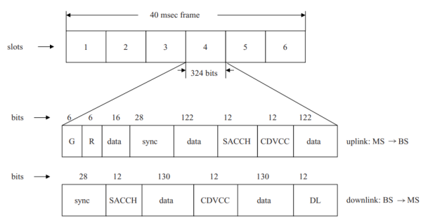
Fig 1: IS-136 slot structure, digital traffic channel
It prevents terminals initiating communication at the same time from interfering with one another. The power ramp-up time R in the same, uplink, slot structure is needed to accommodate terminals that may not be on, and that require time for their transmission power to ramp up to the desired value, depending on location within the cell and measured interference power, as dictated by the base station. Since the base station (BS) is always on and always transmitting, these two fields are not needed in the downlink slot structure
Table DCCH logical control channels, IS-136
Downlink (BS -> MS)
1 Broadcast control channels, BCCH:
Fast broadcast control channel, F-BCCH
Extended broadcast control channel, E-BCCH
SMS broadcast BCCH, S-BCCH
2 SMS point- to – point, paging, and access response channel, SPACH:
Paging control channel, PCH
Access response channel, ARCH
SMS channel, SMSCH
3 Shared control feedback channel, SCF
Uplink (MS->BS)
Random access channel, RACH
A full-rate traffic channel, covering two slots in a frame, has 24 bits per frame devoted to the SACCH. The SACCH control data transmission rate is thus 600 bps in this case. A fast associated control channel, FACCH, is obtained, as in the GSM case, by replacing the 260-bits per slot data fields in the traffic channel with control information. The rate of control data transmission for this channel is then 13 kbps for full-rate channels of two slots per frame.
The SMS point-to-point, paging, and access response channel, SPACH, is a logical channel designed, as the name indicates, to carry paging and access response control information, as well as point-to-point messages concerning the SMS service. Finally, the shared control feedback, SCF, channel is used to carry downlink information, from BS to MS, as part of the random access procedure.
It is used to both indicate to the mobile a random access time slot in which to request access, as well as to provide acknowledgement of the random access request once made. Random access messages, used for call setup or origination, as well as mobile registration and authentication, are carried over the one uplink channel, the random access channel, RACH.

Fig 2 Repetitive super frame structure, IS-136
These channels, in the full-rate version, are transmitted using two slots per frame, generally slots 1 and 4, on selected frequency channels. (We focus here only on the full-rate category.) The broadcast channels are transmitted sequentially using a repetitive super frame structure. The super frame format is diagrammed in Fig. Above. Each super frame corresponds to 16 consecutive TDMA frames, for a total time interval of 640 msec.
The 6-slot TDMA frames are each grouped into two 3-slot blocks and one slot per block (nominally slots 1 and 4, as noted above) is assigned to the DCCH. Each super frame is thus 32 blocks long. As indicated in Fig. Above, the first set of three to ten blocks is assigned to the F-BCCH logical channel. This is followed, in order, by the E-BCCH, covering from one to eight blocks, the S-BCCH, assigned from 0–15 blocks, a group of 0–7 blocks left reserved for other functions if needed, and, finally, the SPACH, assigned the remainder of the 32-block super frame.

Fig 3 IS-136 slot structure, downlink broadcast control channels
The slot format of these control channels appears in Fig. Above. Note that each slot carries the same 28-bit synchronization field and a total of 260 bits of data as does the digital traffic channel. The control slot format differs, however, in having a CSFP field in place of the CDVCC, and 22 bits of SCF in place of the SACCH and DL fields. The SCF bits are, of course, used to carry the SCF logical channel. SCF messages are thus transmitted as part of a control channel slot, rather than in distinct control slots, as is the case of the other downlink broadcast channel messages.
The SCF channel is used, as noted above, to respond to the mobile’s random access attempt. We shall have more to say later about the messages carried by this channel. Continuing our discussion of the control channel slot format, we note that the 12-bit CSFP field (for coded superframe phase) is used to indicate the location of a TDMA block within a superframe. This field carries an 8-bit SFP (superframe phase) number and four parity-check bits to protect this number against errors. Five of the eight bits are used to keep a modulo-32 count of the blocks within the 32-block superframe. The other three bits are reserved and set to 0.

Fig 4 Access procedure, IS-136
We now move to considering the one uplink IS-136 control channel, RACH. This channel is used by the mobile, as already noted earlier, for originating calls, for registration, and for replying to page messages. Its functions are obviously similar to those described previously in discussing GSM. As is the case with the other (downlink) DCCHs discussed above, this channel is carried in time slots 1 and 4 of frames in selected frequency channels.
The IS-136 access procedure using the RACH, in conjunction with the downlink channels, is diagrammed in Fig. Above. This procedure uses the slotted-Aloha access protocol mentioned in discussing the GSM access procedure. The mobile station listens to a downlink SCF channel to determine a specific future time slot to use to send its RACH message. It then sends the RACH message, as shown in Fig. Above.
A later SCF message, carried in a specified time slot, will indicate whether the RACH message has been correctly received and access granted. If access is granted, an ARCH message carried on the SPACH channel will follow, indicating the specific digital traffic channel the mobile is to use for communication. If the access is not successful (other mobiles might be attempting access at the same time) the access attempt will be retried a random time later.
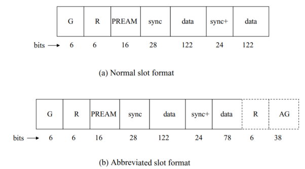
Fig 5 Slot formats, IS-136 RACH
Two slot formats are available for sending RACH messages: a normal slot format, 324 bits long, as is the case for the IS-136 traffic and control channels discussed above, and an abbreviated slot format. The two formats appear in Figs above respectively. Note that they differ in the length of the data fields. The normal format carries a total of 244 data bits; the abbreviated format carries 200 bits. The latter carries instead an added 38-bit equivalent guard time (AG) plus ramp-up time R of six bits.
The overhead fields G, R, and sync are the same guard, ramp-up, and synchronization fields appearing in the uplink traffic channel. PREAM is a preamble field consisting of successive −π/4 phase changes in the DPSK modulation scheme, used to help with symbol synchronization. The added synchronization field, sync+, is needed because the RACH is not used continuously, as is the case with the digital traffic channel, hence added synchronization time is needed.
The initial abbreviated RACH messages are 79 bits long and are then brought up to the 200-bit data field size using the same procedure. There are seven different types of normal RACH frames 117 bits long (including the 16-bit CRC field) that may be transmitted. These include BEGIN, CONTINUE, END, and single BEGIN/END frames, among others.
The BEGIN frame format appears, as an example. The 3-bit BT field is used to distinguish among the seven different types of RACH frames: 000 indicates a BEGIN frame, for example. The mobile station id, MSID, has three possible values: a 20-bit temporary MS id, a 34-bit mobile id corresponding to the normal 10-digit North American telephone number converted to binary format, and a 50-bit international mobile id. The 2-bit IDT field indicates which of these three mobile ids appears in the MSID field. The one-bit EH flag allows an extension header to be present: 0 means no extension header; 1 means it is present.
The 3-bit NL3M field indicates how many concatenated layer-3 messages appear in this BEGIN frame. The L3LI field serves the same function as it did in the F-BCCH format example of Fig. Above It indicates the length, in bytes, of the actual message field, L3 data, following. Eighteen different RACH messages are defined. The messages we have implicitly mentioned, Authentication, Page Response, Origination (call setup), and Registration, are included in this group. Messages are distinguished by a 6-bit message type field included.
Key takeaway
Global system for mobile communication (GSM) is a globally accepted standard for digital cellular communication. GSM is the name of a standardization group established in 1982 to create a common European mobile telephone standard that would formulate specifications for a pan -European mobile cellular radio system operating at 900 MHz.
IS-95 is a CDMA-based system. Its traffic and control channels are defined as specified codes rather than time slots as in the case of GSM and IS-136. The discussion here will thus differ substantially from the description in the prior sections of those two TDMA-based cellular systems. In Figs. Below a binary information stream is “multiplied” by a pseudo-noise (PN) chip spreading sequence, the resulting output shaped by an appropriate low-pass shaping filter, and then fed to a high-frequency transmitter. Modulo-2 (mod-2) addition is used here instead of the multiplication process. It is left to the reader to show that mod-2 addition of binary 1s and 0s is identical to multiplication of the equivalent bipolar (± 1) binary digits.
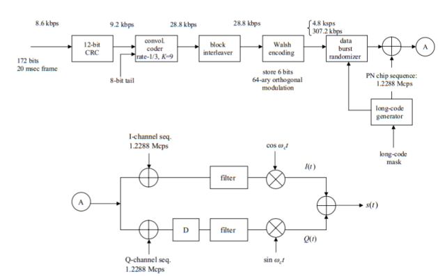
Fig 6 IS-95 reverse traffic channel diagram
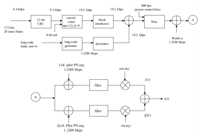
Fig 7 IS-95 forward traffic channel
The diagrams of Figs. Above are those for full-rate traffic transmission of 8.6 kbps, as shown at the top left-hand side of each figure. Reduced transmission rates of 4.0, 2.0, and 0.8 kbps are defined for IS-95 as well. As also indicated at the top left-hand side of each figure, for the full-rate case, IS-95 defines consecutive 172-bit traffic frames, 20 msec long. This obviously equates to a traffic input rate of 8.6 kbps. Twelve forward error-correction bits per frame are then added. In the case of the reverse traffic channel of Fig. Above the resultant 9.2 kbps signal is fed into a rate-1/3, constraint length K = 9, convolutional encoder, with eight all-zero tail bits appended each frame.
The 28.8 kbps convolutional encoder output is then fed into a block interleaver to reduce the effect of burst errors, those lasting many bits, as might result from a mobile undergoing a severe fade. This block interleaver operates consecutively on each frame of 576 bits (28.8 kbps times 20 msec). The block interleaver may be visualized as being a 32-row by 18-column array, as shown in Fig. Below. The interleaver is filled each frame, one column at a time. It is then read out bit by bit, each row at a time: bits 1, 33, 65, 97, . . . , 545, 2, 34, 66, . . . , 546, . . . In succession. This procedure reduces the possible adverse effect of a burst of errors.
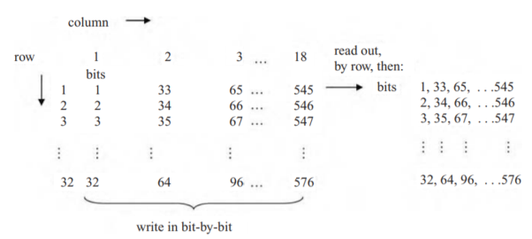
Fig 8 Block inter leaver operation
The block interleaver output at the 28.8 kbps rate is now fed into a 64-ary Walsh encoder, as shown in Figure. Six consecutive bits in the 28.8 kbps stream are stored and used to generate one of 64 orthogonal Walsh functions, a set of binary waveforms (1s and 0s), each 64 bits long. The 28.8 kbps input stream is thus converted to a 307.2 kbps output stream. Why uses this procedure? The Walsh encoder acts as an orthogonal modulator, analogous to the case of using 64 orthogonal sinewaves, but with binary waveforms used instead. This procedure enables non-coherent demodulation to be used at the receiver, followed by deinterleaving and decoding to recover the original message sent. Straight binary PSK would have provided better performance, but would have required coherent demodulation, with a phase reference, such as a pilot signal, necessary to be sent, accompanying the normal signal. Given the level of coherence of the wireless channels over which the IS-95 is used, this was deemed to be impractical, because of the relatively large energy required to send the pilot signal. Differential PSK, such as is used in the IS-136 system provides performance inferior to the Walsh orthogonal scheme used in this system.

Fig 9 IS-95 Call Origination
Channels in the forward, downlink direction are specified by the appropriate one of 64 possible Walsh codes. And by their long-code masks appearing as part of the PN chip sequences in the reverse, uplink direction. As shown in Fig. Above, the mobile initiates call setup by sending an Origination message over the access channel. Assuming this message is received correctly, the base station responds by sending a Channel Assignment message over the paging channel. This message indicates to the mobile the forward traffic channel (Walsh code) on which the base station will be transmitting, and to which its receiving code for the traffic channel is to be set.
The mobile, on receipt of the Channel Assignment message, begins sending a traffic channel preamble over the reverse traffic channel, consisting of continuous zeros at the 9600 bps rate, which is used by the base station to acquire that channel. The base station now sends a Base Station Acknowledgement Order over the forward traffic channel, and two-way conversation over the traffic channels may now begin.
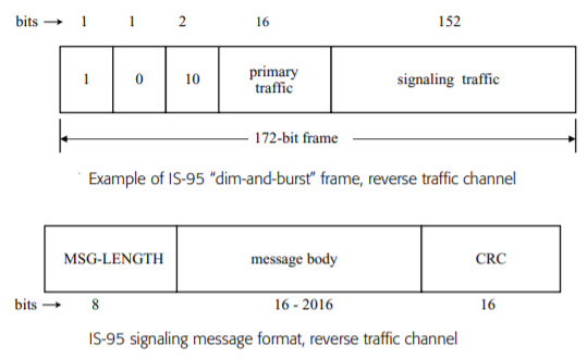
Fig 10 IS-95 Signalling message format
Four frames are thus needed to carry this message. The first bit of the 88 signalling bits in each frame is used to indicate whether the frame in question is the first frame of the message or a continuing frame. Eighty-seven bits per frame thus remain to carry the signalling message. Two hundred and sixty-one bits are thus carried in the first three frames; the remaining 59 bits are carried in the fourth and last frame. The 28 bits left over in that frame must then be filled by all-zero padding bits. The message-length indicator is used by the base station, on receiving this message, to delete the padded bits. There are a variety of reverse traffic signalling messages defined in IS-95, each of varying length, depending on the information to be sent.
Examples include a Pilot Strength Measurement message, that provides to the base station a 6-bit indication of the mobile’s measurement of the signal power of the pilot used by the mobile to derive its time reference; a Power Measurement Report message that provides the base station with the power measured by the mobile for each of the pilots in its active set, as well as the number of frames used in making this measurement; an Origination Continuation message that contains any dialled digits not included in the Origination message sent over the access channel.

Fig 11 IS-95 Access channel message capsule
Signalling over the forward traffic channels is carried out much like signalling over the reverse traffic channels just discussed: the forward traffic channel is also organized into 172-bit frames. These frames carry a combination of primary traffic (principally voice messages), signalling traffic messages, and secondary traffic, and are organized in the same manner as reverse traffic frames.
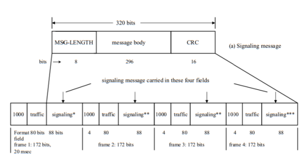
Fig 12 Signalling message carried over 4 frames
Key takeaway
IS-95 is a CDMA-based system. Its traffic and control channels are defined as specified codes rather than time slots as in the case of GSM and IS-136. The discussion here will thus differ substantially from the description in the prior sections of those two TDMA-based cellular systems.
Architecture

Fig.13 GSM Architecture
In this architecture, a mobile station (MS) communicates with a base station system (BSS) through the radio interface. The BSS is connected to the network and switching subsystem (NSS) by communicating with a mobile switching centre (MSC).
The Switching System
The switching system (SS) is responsible for performing call processing and subscriber-related functions. The switching system includes the following functional units:
• Home location register (HLR)—The HLR is a database used for storage and management of subscriptions. The HLR is considered the most important database, as it stores permanent data about subscribers, including a subscriber's service profile, location information, and activity status. When an individual buys a subscription from one of the PCS operators, he or she is registered in the HLR of that operator.
• Mobile services switching center (MSC)—The MSC performs the telephony switching functions of the system. It controls calls to and from other telephone and data systems. It also performs such functions as toll ticketing, network interfacing, common channel signalling, and others.
• Visitor location register (VLR)—The VLR is a database that contains temporary information about subscribers that is needed by the MSC in order to service visiting subscribers. The VLR is always integrated with the MSC. When a mobile station roams into a new MSC area, the VLR connected to that MSC will request data about the mobile station from the HLR. Later, if the mobile station makes a call, the VLR will have the information needed for call setup without having to interrogate the HLR each time.
• Authentication centre (AUC)—A unit called the AUC provides authentication and encryption parameters that verify the user's identity and ensure the confidentiality of each call. The AUC protects network operators from different types of fraud found in today's cellular world.
• Equipment identity register (EIR)—The EIR is a database that contains information about the identity of mobile equipment that prevents calls from stolen, unauthorized, or defective mobile stations.
The AUC and EIR are implemented as stand-alone nodes or as a combined AUC/EIR node.
The Base Station System (BSS)
All radio-related functions are performed in the BSS, which consists of base station controllers (BSCs) and the base transceiver stations (BTSs).
• BSC—The BSC provides all the control functions and physical links between the MSC and BTS. It is a high-capacity switch that provides functions such as handover, cell configuration data, and control of radio frequency (RF) power levels in base transceiver stations. A number of BSCs are served by an MSC.
• BTS—The BTS handles the radio interface to the mobile station. The BTS is the radio equipment (transceivers and antennas) needed to service each cell in the network. A group of BTSs are controlled by a BSC
-Mobile station (MS) – The MS consist of two parts the SIM (subscriber identity module) and the ME (mobile equipment)
An SIM can be
- A smart card, usually size of credit card
- A smaller sized ‘plug-in SIM” that can be broken out of it
The SIM is protected by a personal identity number (PIN) between four to eight digits in length. The PIN is loaded by a network operator at subscription time.
A SIM contain the subscriber-related information, including the PIN & PUK (PIN unblocking key) codes.
The ME contain the noncustomer-related hardware & software specific to the radio interface. When the SIM is removed from an MS the remaining ME cannot be used for reaching the services, except from emergency call.
This SIM-ME design supports portability as well as enhancing security. Usually, the ME is the property of subscriber.
Key takeaway
In this architecture, a mobile station (MS) communicates with a base station system (BSS) through the radio interface. The BSS is connected to the network and switching subsystem (NSS) by communicating with a mobile switching centre (MSC).
Mobility Management function handles the function that arises due to mobility of the subscriber. Main objective of MM is location tracking & call set up. The current location of an MS is maintained by a 2-level hierarchical strategy with HLR & VLR. When an MS visits a new location, it must register in the VLR of visited location. The HLR must be informed about the registration. The registration process of MS moving from one VLR to another VLR follows following steps.
STEP-1.
MS periodically listens to the BCCH (Broadcast Control Channel) broadcast from BSS. If the MS detects that it has entered into a new location area, it sends a registration message to the new VLR by using SDCCH (Standalone Dedicated Control Channel) channel.
SDCCH: Used only for signalling & short message.
BCCH: Provides system information.
STEP-2.
The new VLR communicates with old VLR to find HLR of MS. The new VLR then performs authentication process.
STEP-3
After MS is authenticated, new VLR sends a registration message to HLR. If the registration request is accepted, the HLR provides new VLR with all relevant subscriber information.
STEP-4
The new VLR informs the MS of successful registration.
STEP-5
Then the HLR sends a deregistration (Cancellation) message to old VLR. The old VLR cancels the record for MS & sends an acknowledgement to the HLR regarding cancellation.
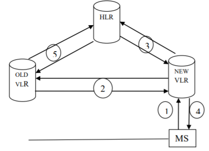
Fig 14 GSM Mobility Management
GSM Call Origination
1. MS sends the call origination request to MSC.
2. MSC forwards the request to VLR by sending MAP_SEND_INFO_ FOR_OUGOING_CALL.
3. VLR checks MS’s profile & sends an ACK to MSC to grant call request.
4. MSC sets up communication link according to standard PSTN call set up procedure.
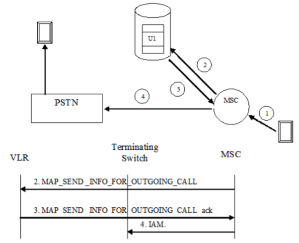
Fig 15 Call Origination Operation
Call Termination
When mobile station number is dialled by PSTN user, call is routed to GMSC by IAM (Initial Addressing Message) message.
1. To obtain routing information, GMSC interrogates HLR by sending MAP_SEND_ ROUTING_INFORMATION to HLR.
2. HLR sends a MAP_PROVIDE_ROAMING_NUMBER message to VLR to obtain MSRN (MS Roaming Number). The message consists of IMSI, MSC number etc.
3. The VLR creates the MSRN by using MSC number stored in VLR record of MS. The MSRN no is sent back to GMSC through HLR.
4. MSRN provides address of target MSC where the MS resides. Then a message is directed from GMSC to target MSC to set communication link.
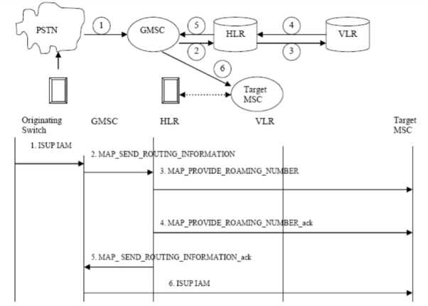
Fig 16 Call Termination Operation
Key takeaway
Mobility Management function handles the function that arises due to mobility of the subscriber. Main objective of MM is location tracking & call set up. The current location of an MS is maintained by a 2-level hierarchical strategy with HLR & VLR. When an MS visits a new location, it must register in the VLR of visited location. The HLR must be informed about the registration.

Fig 17 Network Signalling
- LAPD Link Access Procedure D-Channel Managed
- RR: Radio Resource
- MM: Mobility Management
- CM: Call Management
- BTSM: BTS Management
- BSSMAP: BSS Application Protocol
- SCCP: Signalling Connection Control Part
The signalling protocol in GSM is structured into 3 layers.
Layer1 Physical Layer
Layer2 Data Link Layer
Layer3 Network Layer
MS BTS
The physical layer between MS & BTS is called Um interface. It performs following functions
- Full or half duplex access.
- Provides TDMA, FDMA, and CDMA.
- Framing of data.
The data link layer controls the flow of packets to and from network layer and provides access to various services like: Connection: Provides connection between two terminals. Teleservices -Services offered by a mobile network to users like: MMS, SMS, etc. The data link layer present between MS & BTS is LAPDm (Link Access Protocol managed). LAPDm protocol describes the standard procedure in GSM for accessing D channel Link. Its functions are:
- Dataflow control.
- Acknowledged / unacknowledged data Transmission.
- Address and sequence no. Check.
- Segmentation.
The network layer has 3-sublayers
CM (Call Management) Supports call establishment, maintenance, termination. It supports SMS. Support DTMF (Dual Tone multiple frequency) signalling.
MM (Mobility Management) Control the issue regarding mobility Management, location updating & registration.
RRM (Radio Resource Management.) It manages radio resources such as: frequency assignment, signal measurement.
BTS BSC signalling protocols
The physical layer between BTS & BSC is called Abis interface, where voice is coded by using 64kbps PCM. The connection between BTS and BSC is through a wired network. The data link layer is LAPDm. Network Layer protocol is called BTS Management which interact with BSSAP.
BSC MSC signalling protocol
Physical layer between BSC & MSC is called U interface. Data link layer protocol between BSC & MSC is MTP (Message Transfer Protocol) & SCCP (Signalling Connection Control Protocol). MTP and SCCP are part of the SS7 (Signalling System No7) used by interface A. NETWORK layer protocols at the MSC are CM, MM and BSSAP
The control required to handle the movement of mobiles is referred to as mobile management. The movement of mobiles involves essentially three functions: handoff control, location management, and paging. Handoff control is required as a mobile, involved in an on-going call, moves from one cell to an adjacent one, or from the jurisdiction of one system to another. A new set of transmission channels must be allocated to the handoff call without perceptible notice by the mobile user or interruption to the call. These two types of hands-off are called, respectively, inter-cellular and inter-system handoff. (Standards outside North America often use the term handover instead.)
Intra-cellular handoff is possible as well, when the mobile/base station combination determines that power considerations or channel fading warrants changing channels within a cell. Location management is required to handle the registration of a mobile in areas or regions outside its home area, to enable it to be located and paged in the event of an incoming call.
The term location or registration area is used to designate a region of multiple cells, each with its base station, controlled by an MSC. On registering in a different region, a visitor’s location register, VLR, is used to store the visiting mobile’s reference and profile information, after communication takes place with the MSC and HLR of the home area. This registration information is subsequently used to page a mobile when an incoming call is directed to it, after first querying the home MSC and HLR as to the visiting location area. A Page message is sent by the visiting MSC to all base stations under its control, which, in turn, broadcast a Page message over their paging channels.
We begin with handoff control, discussing first inter-cellular, and, then, inter-system handoff. We then move on to location management and paging, concluding with a simple consideration of trade-offs involved in dealing with these two conflicting functions.
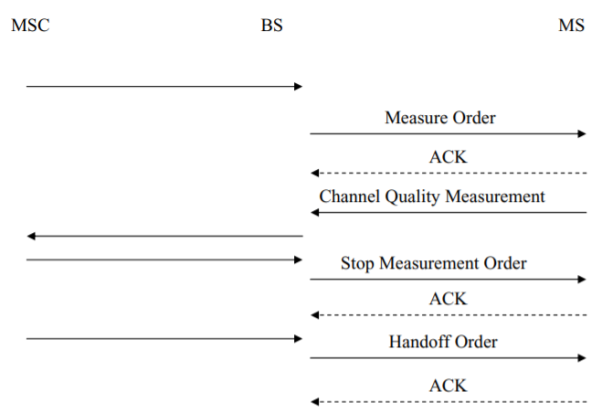
Fig 18 Mobile assisted hand-off
Consider a communicating mobile traveling within a given cell. As it reaches the boundary (generally ill-defined) of that cell, the power received from the cell base station with which the mobile has been in communication across the air interface between them will drop below a pre-defined threshold. In contrast, assume the power received from a neighboring base station exceeds a threshold. A decision to handoff to the neighboring base station and enter the new cell associated with that base station would then be made by the MSC controlling both base stations. Second-generation wireless systems support mobile assisted handoffs (MAHO) in which power measurements are carried out by a mobile under the command of the MSC and base station, with the results of the measurements transmitted to the base station as uplink signalling messages.
GSM uses a similar handoff strategy. From above diagrams the messages transmitted between the MSC, base station, and mobile as mobile-assisted handoff is carried out. The MSC notifies the base station that channel quality measurements are to be carried out. The base station responds by transmitting to the mobile a Measurement Order message identifying neighboring forward traffic channels, as well as the forward traffic channel over which it is currently receiving messages from the base station, for which channel quality is to be measured. Channel quality measurements consist of received signal strength measurements for the current and neighboring traffic channels, and bit error rate measurements for the current traffic channel. The results of these measurements are reported back to the base station by the mobile, when they are completed, in a Channel Quality Measurement message carried on the SACCH. The base station, in turn, forwards the measurement results to the MSC, which then issues a stop measurements command, sent on to the mobile by the base station as a Stop Measurement Order message. If, on analysis of the measurements, handoff is deemed necessary, the MSC so orders, with the base station then signalling the mobile to which new channel to tune.
Handoff of a mobile to a new base station thus results in the immediate need to allocate to the mobile a channel within the new cell. Should a channel not be available, the ongoing call would have to be dropped. The dropping probability of a handoff is clearly the same as that of blocking a newly generated call if new calls and handoffs are treated alike in the allocation of channels. It is generally agreed that mobile system users find the dropping of ongoing calls much more onerous than receiving a busy signal on attempting to initiate a call, i.e., having a new call attempt blocked. After all, it is distinctly unpleasant to be cut off in the middle of a conversation! A number of proposals have thus been made to reduce the probability of dropping a call. These include, among others, giving handoff calls priority over new call attempts or queueing handoff calls for a brief time while waiting for a channel to become available. With a fixed number of channels available, giving priority to handoff calls obviously increases the probability of blocking new calls.
In the soft handoff procedure, a mobile makes a connection to two or more base stations before choosing the one with which to communicate. It is thus an example of a “make before break” operation. Hard handoff implies the connection with the current base station is broken before connecting to the new one. IS-95 systems, in carrying out handoffs, use mobile-assisted handoffs, as do IS-136 and GSM. But, unlike the handoff procedure adopted for these other systems, in IS-95 it is the mobile that initiates the handoff procedure. It is the mobile that determines handoff may be necessary based on measurements it carries out. It is left to the MSC, however, to actually make the decision to hand off. A handoff is completed when the MSC commands the mobile, by sending messages to the base stations involved, to drop the old base station connection and continue with the new base station connection. But connections to the old and new base stations are maintained until the decision to connect to the new base station only is made. This is the essence of soft handoff.
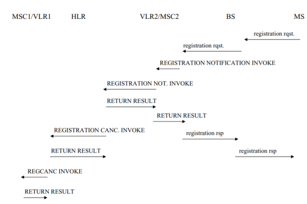
Fig 19 Location Registration
We now move to a brief description of location management. Recall that location management refers to the requirement that roaming mobiles register in any new area into which they cross. They can then be paged in the event of incoming calls. An area consisting of multiple cells is controlled by an MSC. We again discuss the North American standard as described in IS-41. The procedures prescribed for GSM are quite similar. Associated with each MSC service area, often referred to in the location management literature as a location or registration area, is a Visitor Location Register, VLR, which maintains the data base of foreign mobiles registered in that area. Base stations within a given area periodically broadcast the area id. A roaming mobile, on entering a new area, senses, by listening to the base station broadcast, that it has crossed into a new area and begins the registration process. Figure above diagrams an abbreviated version of this process. The mobile is assumed in this figure to have earlier been in the area controlled by MSC-1, with its associated VLR1. It has now crossed over to the area controlled by MSC-2 containing VLR2. The mobile’s home location register HLR shown, located in its home area, maintains a record of its id, subscriber information, and current location information.
MSC-B, carrying the cell id in MSC-B it has designated as the cell to handle the mobile. If MSC-B finds an available voice channel in the designated cell, it replies with a RETURN RESULT message. MSC-A then commands mobile m to switch to that voice channel. With the mobile on that channel, MSC-B sends a Facilities Release INVOKE, releasing the inter-MSC circuit. Handoff is now complete. Other inter-system procedures defined in IS-41 involve cases in which an initial handoff is returned to the original MSC (handoff-back) or continued on to a third MSC.
The mobile, on crossing into area 2, sends a registration message to the base station whose broadcast it hears, which, in turn, forwards that message to the area MSC. The message contains the mobile identification number MIN. MSC-2 now sends an IS-41- defined REGISTRATION-NOTIFICATION INVOKE message containing the MIN to its VLR. (The VLR could actually be co-located with the MSC.) VLR2, noting this mobile is not currently registered, forwards the message to the mobile’s HLR, using the MIN to determine the HLR. The HLR acknowledges receipt of this message with a REGIS.NOT. RETURN RESULT message sent back to VLR2, enters the new location of the mobile in its data base, and then sends a REGISTATIONCANCELATION INVOKE to VLR1, which forwards this message to its MSC. This cancels the mobile’s registration in area 1. Other acknowledgement messages, acknowledging receipt of each message sent, appear in Fig. Above as well. Note, in particular, that each registration requires eight SS7 messages, including acknowledgements, to be sent between the various VLRs, MSCs, and the HLR.
Four other messages across the air interface and between base station and its MSC are generated as a result of the registration. We ignore here additional messages that would have to be sent to handle any errors or untoward events. The assumption here is that registration proceeds smoothly and correctly. Even without these other messages that might have to be sent, it is clear that registration message activity could end up requiring a sizeable fraction of system capacity, depending on the size of a location area and the density of mobiles within it. Mobile power is also impacted by registration activity. Increasing the size of a location area would obviously reduce a mobile’s border crossings requiring registration, hence reduce per-mobile registration activity. But, as we shall see next, in discussing paging of mobiles, an increase in area size results in more paging messages sent to locate a mobile within a location area. There is thus a trade-off between location management and paging, as noted at the beginning of this section.
Consider a location area of area A which contains within it N cells, each of area a. Say the area extends, on the average, R m from its center to its border. Call this the “radius” of the area. A circular or hexagonally shaped area would thus have R as the radius. Figure above shows as an example a square area. Let the cells within it have a corresponding radius of r m. It is then clear that we must have R = √Nr. Say there are m uniformly distributed mobiles within this area. The average velocity of a mobile is taken to be V m/sec, uniformly distributed over all directions. A little thought will indicate that it takes an average mobile o(R/V) second to reach a border (“o” means order of). A typical mobile thus undergoes o(V/R) = o (V/r √N) border-crossings/sec. A more detailed analysis, using a fluid-flow model with mobiles represented as infinitesimally small particles of fluid, shows that the average rate of crossing an area of size S is V L/π S, with L the perimeter or boundary length.

Fig 20 Location Area
For a circle or square of radius R, this becomes 2V/πR. For a hexagon, this is 2.3V/πR. We shall henceforth use the value 2V/πR = 2V/πr √N for the average rate of location area border crossings per mobile. Note now that if each border crossing results in l location messages being transmitted, the average rate of transmitting location messages is, of course, 2lV/πr √N. Note that the IS-41 location registration scenario results in a total of l = 12 messages of all types transmitted. If messages transmitted across the air interface only are considered, i.e., those involving the mobile terminal directly, then l = 2.
Let each page require p messages to be transmitted. For the case of, p = 8 + 2N, as noted above. The average number of paging messages transmitted per unit time is thus λpp = λp (8 + 2N). The total number C of messages transmitted per unit time per mobile due to registration and paging is thus given by
C= 2lV/πr √ N + λp (8 + 2N)
The value of N that results in this minimum cost value is readily found by the usual technique of setting the derivative of C with respect to N equal to zero, if we assume, for simplicity, that N is a continuously varying variable. Carrying out this differentiation, we find the “best” choice of N, the number of cells defining a location or registration area, to be given by
Nopt = (lV/2πrλp) 2/3
We take three cases: a macrocell example, a medium-sized cell, and a microcell. Let l = 12 location messages be required to be transmitted for each border crossing, as suggested by Fig. 8.37. We take the paging rate per mobile to be λp = 1 incoming call per hour. (The effect of doubling this rate will be considered below. Readers can vary this rate and see for themselves its effect on size of location area.) The resultant approximate values of Nopt for different mobile speeds and cell sizes are tabulated as follows:
1 Macrocell (1)r = 10 km, V = 60 km/hr (2)r = 15 km, V = 100 km/hr Nopt = 5 cells per area in both cases
2 Medium-sized cell (urban environment), r = 1 km
(1) walking case V = 5 km/hr Nopt = 4
(2) vehicle V = 50 km/hr Nopt = 20 or 21 (If the average paging rate is increased to 2 calls/hr per mobile, the numbers of cells per location area decrease to 3 and 13 or 14, respectively.)
3 Microcell-r = 100 m, V = 5 km/hr Nopt = 20 or 21
These examples demonstrate the expected results, as indicated by intuition and, more specifically as mobile velocity increases, with cell size fixed, the location area should be increased, to reduce the number of border crossings with attendant registrations required. As cell size is reduced, with mobile speed fixed, the location area size should also increase. As the incoming call rate increases, however, the location area size should be reduced.
Key takeaway
They focus on the simplest possible flow model with mobile density assumed uniformly and densely distributed throughout a region. Average velocity and average paging rate only are considered. More detailed studies and analyses have appeared in the literature. Some of these studies have incorporated probabilistic distributions of mobile locations and velocities. A number of different algorithms to reduce location and/or paging cost have been studied and compared as well.
We have focused thus far in this chapter on signalling messages in second-generation systems and how they are transmitted via signalling channels. In this section we finally consider the major application of these systems, that of transmitting voice signals. Voice signals are transmitted at considerably reduced rates compared with the rates used in wired digital telephone systems. This is necessary because of the relatively low bandwidths available in wireless cellular systems. The harsh transmission environment involving fading and interference from mobile terminals requires strong error protection through coding as well. Two steps are therefore necessary in transmitting voice messages over the wireless air interface. The voice signals must first be compressed significantly to reduce the bit rate required for transmission. Coding techniques must then be used to provide the error protection needed. Both steps must clearly result in voice signals that are acceptable to a receiving user

Fig 21 LPC speech model

Fig 22 Linear Prediction
The second-generation cellular systems, choosing to compress voice signals significantly to uncoded data rates ranging from 8 kbps in the case of IS-136 to 13 kbps in the case of GSM, have all adopted variations of a compression technique called linear predictive coding (LPC). LPC basically starts by modeling the human speech generation process as an excitation waveform driving a set of linear filters. The LPC speech model is depicted in Figure. The excitation waveform and long-term filter model speech sounds generated by the lungs and vocal cords; the short-term filter represents the vocal tract. Two types of sound are generally recognized: voiced and unvoiced.
Voiced sounds due to the opening and closing of the vocal cords tend to be quasi-periodic in form; unvoiced sounds are due to turbulent air created by constrictions in the vocal tract. The excitation waveforms appearing in the LPC model of Fig. Above would thus be a combination of periodic pulses and a noise-like (random) signal. The term “long-term” used in describing the first of the two filters in Fig. Above refers roughly to the pitch period of the voiced sounds due to the vibration of the vocal cords. The pitch period tends to be in the order of 3–15 msec (Rabiner and Hwang, 1993). “Short-term” implies times in the order of 1 msec
The linear predictor model may be written quite simply as

Taking the z-transform

This transfer function is exactly that of an all-pole linear filter. The number of samples m is typically ten or so, meaning the filter operates over the relatively “short” time of 1 msec, as already noted. The model for the “long-term” filter is usually taken to be that of an all-pole filter also, but with only one or two poles. Specifically, say it is represented by a one-pole filter. Its transfer function is thus clearly given by

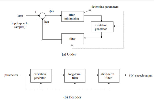
Fig 23 LPC System
The basic LPC system used to compress speech is given by the block diagrams of Fig. Above. This system compares the output of the model with the actual speech samples and attempts to minimize the difference (error) signal by adjusting the excitation and filter parameters periodically. It shows both a coder at the speech generating side (Fig.(a)) and a decoder at the receiving side (Fig.(b)). The combined system is normally called a speech codec. Consider the coder first. Quantized input speech samples labeled s(n) are generated every 125micro sec. The difference ε(n) between these and the speech model output sˆ(n) is minimized by adjusting the excitation generator and filter parameters.
In particular, GSM uses a scheme called LPC with regular pulse excitation (LPC-RPE). IS-136 and IS-95 use as their voice codecs variations of the code-excited linear predictive coding (CELP) scheme. We now describe these different coding–decoding techniques. Consider the CELP technique first. A block diagram of the basic CELP scheme appears in Fig. Below. The basic difference is that the excitation generator of Fig. Below is given by a selected set of gaussian (i.e., random) codewords. The parameter G shown represents a gain factor adjusting the amplitude of the codewords selected.
This is a technique in which parameter adjustments are made periodically, after a number of quantized error samples, constituting a vector, have been collected. Vector quantization has been shown to provide compression advantages.
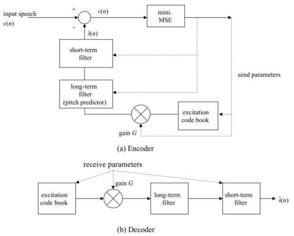
Fig 24 CELP System
Key takeaway
Voice signal compression has been an ongoing concern for many years. Multiple techniques have been proposed, investigated, standardized, and implemented. Early digital telephony standardized on 64 kbps PCM voice transmission, attained by sampling 3.2 kHz bandlimited voice 8000 times per second and then using eight bits per sample to provide acceptable speech quality for telephone applications. This technique relies on application of the Nyquist sampling theorem, which states that by sampling a bandlimited signal at a rate at least twice the bandwidth the signal can be retrieved with no distortion.

Fig: 25 General spread spectrum structure
- Spread spectrum is specially used for wireless communication signal spreading. Transmitted signals frequency varies deliberately.
- Frequency hopping and direct sequence are two popular spread spectrums.
- In frequency hopping, signals are broadcast over any random series of frequency while in direct sequence each bit is in order of multiple bit of transmitting signal it uses chipping code.
Frequency Hoping Spread Spectrum (FHSS)
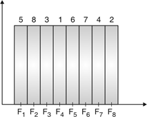
Fig.26: Channel assignment
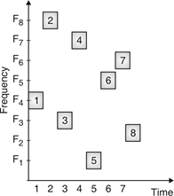
Fig.27 Channel use

Fig.28: FHSS (Transmitter)
In FHSS, according to PN sequence RF carries frequency used to get change.
FHSS has two types
1. Fast hopped FHSS.
2. Slow hopped FHSS.
Hopping is done with faster rate compared to bit rate in fast hopped FHSS while slow rate compared to message bit rate in slow hopped FHSS.
FHSS systems rely on changes in RF carrier frequencies which turn into burst errors.
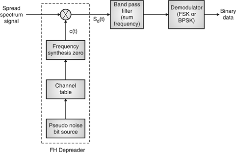
Fig:29 FHSS (Receiver)
Direct Sequence Spread Spectrum (DSSS)

Fig:30 DSSS (Transmitter)
- Base of DSSS is key to a successful recovery of message is the knowledge about PN sequence which is used at the transmitter.
- Information bits are spread across frequency as well as time, it result by minimizing effects of interference and fading. It somehow prone to error comparably FSSS system.
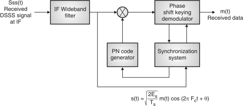
Fig:31 DSSS (Receiver)
Key takeaway
System Behaviors | FHSS | DSSS |
System Collocation | It is easier to use FHSS for installations of coverage and multiple collocated cells. | DSSS can be used but collocated cells must be non-overlapping cells at the radio level which is required using directional antennas. |
Noise and interference immunity | FHSS system operate with SNR of about ls8 dB | DSSS systems operate with SNR 12dB because Phase-Shift keying is used. |
Near or Far problem | If the receiver uses FHSS, the worst case will be foreign transmitter, which will block some hops. | In DSSS systems, the problem is more critical and signals generated by the foreign transmitter could not be heard at the receiver. |
Throughput | FHSS system never collide. They provide more or less the same throughput as DSSS systems. | DSSS systems provide greater throughput than with non-synchronized FHSS. |
Multipath Immunity | An FHSS system shows more resistance to multipath immunity. | For long distance systems, the use of directional antennas may help reducing the multipath sensitivity in DSSS systems. |
Security | In FHSS, frequencies may be selected by the user and there is no need for application-level encryption. | DSSS systems use spreading sequence of l1 chips, which modulate 14 channels and it needs message encryption at the application layer. |
Bluetooth Interference | Bluetooth radio is a FHSS operating in the 2.4GHz band. | DSSS is more sensitive to Bluetooth interference rather than in the FHSS systems. |
Two criteria must be met to qualify as a Spread Spectrum Signal;
1. The signal bandwidth must be wider than the information bandwidth.
2. Some code or pattern, other than the data to be transmitted, determine the actual on air transmit bandwidth
Interference Immunity – Spread Spectrum radios are inherently more noise immune than conventional radios.
Multichannel Capability – Spread Spectrum radios offer the ability to have multiple channels, which can be changed dynamically through software
CDMA is an American Standard that was developed by Qualcomm. It was originally developed for the battlefield because it is very hard if not impossible to intercept due to their spread spectrum nature. CDMA is now defined by a number of standards, some of which are IS-95, J-STD-008 (PCS) and CDMA 2000.
A unique code is assigned to all digital speech bits and the signals spread across the broad spectrum of the RF. Each CDMA base station can use the same 1.25 MHz carrier at the same time. There are a maximum of 64 Walsh noise codes per 1.25MHz in a CDMAOne system. CDMA networks have pilot channels which carry no data but are used by the subscriber’s mobile unit to acquire the system and assist in the soft handoff process. A separate pilot channel is transmitted for each sector of a cell site and is uniquely identified by its own PN code, just like other users.
CDMA refers collectively to three CDMA standards that were the first formal specifications assigned to the technology;
1. IS-95A
2. IS-95B
3. J-STD-008
CDMAOne standards have evolved in the complexity and effectiveness. Earlier versions (IS-95A&B) had issues with voice quality, data throughput and were limited in the methods in which they transmitted data. IS-95B and J-STD-008 allowed for Integrated Service Digital Network or ISDN to be used. More advanced calling features were accessible.
CDMA 2000 falls under the specification known as IS-2000 as is backward compatible with earlier versions. CDMA2000 is a 3G specification, which allows for multidata platform usage.
Near -Far Problem
Users may be received with very different powers: ¾ Users near the base station are received with high power. Users far from the base station are received with low power. For a path loss exponent of 4 and a cell size of 1 km, example:

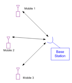
Fig 32 BS for multiple access
Nearby users will completely swamp far away users
In cellular networks, a BS serves al1 MSs in its service area. Two-way communication is conducted between the BS and all the active MSs. The forward link is in the direction from BS to MSs and the reverse link is from MS to BS. And the current CDMA standard OS-95), there is a pilot signal transmitted over the forward link, (FL) but not over the reverse Link (RL). Since al1 MSs share the same frequency spectrum simultaneously, Co-channel interference exists. The forward link interference is generated by several non-moveable BSs in neighboring cells, and also by the fact that each signal is made up from several overlapped signals. The reverse link interference is generated by a large number of moving MSs which are in the reference ce11 and its neighboring cells.
CDMA system capacity is interference limited and any reduction in interference directly contributes to a capacity increase. Because the power control can reduce excessive mutual interference, it is a very important approach to increase system capacity. Due to the non-zero cross correlations between the spreading sequences of the different MSs and/or asynchronous transmission, CO-channel multi-user interference limits the capacity of CDMA systems.
Due to the path loss, in the reverse link, an MS closer to the BS could be received at a higher power level than other MSs without power control. If the difference between the received power level is too hi&, the closer one may cause a great interference to other MSs. This is the so called near-far effect. Fortunately, the near far effect on the forward link is not significant.
If the power of an MS stays away from a suitable level, the MS may either interfere with others or be interfered with by others, resulting in a smaller system capacity. Therefore, power control is necessary. Due to the different nature of forward and reverse links, different power control schemes are used. Power control aims to keep the received power at a preferred level to maximize the system capacity. It is essential to the operation of CDMA cellular networks.
In brief some form of power control mechanism is required in an environment that experiences excessive path loss (shadowing), and/or slow and fast fading, in order to compensate for the fluctuations in the power levels, and to mitigate the near-far problem. Power control cm be implemented by two means: closed loop power conh-01 and open loop power control The closed loop power control accomplishes close estimate to the desired level at the receivers. The receivers constantly observe the received signal quality (may be reflected by signal strength, Le., signal-to-interference ratio (SIR), bit-error rate (BER), and delay) and determine appropriate power control commands.
A feedback channel is necessary to transmit these commands to the senders for power adjustments. For example, power control commands are transmitted from a BS to an MS to raise or lower the MS's transmitted power according to whether the measured SIR at the BS was lower or unnecessarily higher than a desired value. Therefore, the reverse link power level is controlled by the BS. The open loop power control does not need a feedback channel. The transmitting power level adjustment is determined based on the estimation of the channel quality of the opposite direction.
The estimation error of the open loop power control can be rather high, especially when the forward link and the reverse link are not highly correlated. When the open loop power control is adopted in the reverse link, an MS measures the received power level of the pilot from the BS in the forward link and sets the transmitted power level inversely proportional to the pilot level. The following assumption is implied in this power control: A stronger pilot indicates a better forward link; a better forward link indicates a better reverse link; and a better reverse link needs to reduce MS's transmission power.
Closed loop power control and open loop power control have both advantages and disadvantages. Closed loop power control is more complex, has more overhead cost, and longer response delay compared to the open loop power control. The both schemes meet different requirements and accomplish different purposes. Power control changes the statistical characteristics of both the interference and the signal.
Moreover, as BSs cm be more complex than MSs, the calculations of power control should be placed at the BS. It has been shown that a poorly power controlled CDMA system dramatically loses its capacity compared with a well power controlled one. The target value of the controlled power can be presented either in terms of power strength or signal to interference ratio (SIR). When power strength is used, referred to as a strength-based power control, dl MS's power at the BS should be controlled equal in strength. Similarly, SIR-based power control keeps al1 MSs having the same SIR at the BS.
Since the received power level of an MS, which is required to keep a certain SIR, may Vary depending on the population of active MSs (the more MSs, the higher the mutual interference and the higher the signal power needed), the power level might not be constant in SIR-based power control as that in a strength-base power control. Of course, either the chosen target strength or the chosen target SIR is minimized, such that the power consumption at MSs is minimized while keeping the quality of the communications.
Key takeaway
CDMA system capacity is interference limited and any reduction in interference directly contributes to a capacity increase. Because the power control can reduce excessive mutual interference, it is a very important approach to increase system capacity.
Due to the non-zero cross correlations between the spreading sequences of the different MSs and/or asynchronous transmission, CO-channel multi-user interference limits the capacity of CDMA systems.
- Multi path causes large and rapid fluctuations in a signal
- These fluctuations are not the same as the propagation path loss.
Multipath causes three major things in wireless communication
- Rapid changes in signal strength over a short distance or time.
- Random frequency modulation due to Doppler Shifts on different multipath signals.
- Time dispersion caused by multipath delays
- These are called “fading effects
- Multipath propagation results in small-scale fading.
Impulse response model of multipath channel
Mobile radio channel may be modeled as a linear filter with time varying impulse response in continuous time. To show this, consider time variation due to receiver motion and time varying impulse response h(d, t) and x(t), the transmitted signal.
The received signal y (d, t) at any position d would be
y (d, t) = x(t) ∗h (d, t) = x(τ) h (d, t −τ) dτ
For a causal system: h (d, t) = 0, for t < 0 and for a stable system ¸
∞−∞|h (d, t) |dt<∞
Applying causality condition in the above equation,
h (d, t −τ) = 0 for t −τ <0⇒ τ > t,
i.e., the integral limits are changed τ
(d, t) =¸ tx (τ) h (d, t −τ) dτ.−∞
Since the receiver moves along the ground at a constant velocity v, the position of the receiver is
d = vt,
i.e. (vt, t) =¸ tx (τ) h (vt, t −τ) dτ.−∞
Since v is a constant, y (vt, t) is just a function of t. Therefore, the above equation can be expressed as
y(t) =¸ tx(τ) h (vt, t −τ) dτ = x(t) ∗h (vt, t) = x(t) ∗h (d, t)
It is useful to discretize the multipath delay axis τ of the impulse response into equal time delay segments called excess delay bins, each bin having a time delay width equal to
(τi+1 −τi) = ∆τ and τi = i∆τ for i ∈ {0, 1, 2, ..N −1},
Where N represents the total number of possible equally-spaced multipath components, including the first arriving component.
The useful frequency span of the model is 2/∆τ. The model may be used to analyze transmitted RF signals having bandwidth less than 2/∆τ.
If there are N multipaths, maximum excess delay is given by N ∆τ.
{y(t) =x(t) ∗h(t, τi)|i=0,1,...N−1}
Bandpass channel impulse response model is x(t) →h(t,τ) =Re{ hb(t,τ) ejωct → y(t) =Re{r(t) ejωct}
Baseband equivalent channel impulse response model is given by
c(t) →2 hb(t, τ) →r(t) = c(t) ∗2 hb(t, τ)
Average power is x2(t) = 1 c(t)2
The baseband impulse response of a multipath channel can be expressed as
N−1 hb(t, τ) = . Ai(t, τ) exp[j(2πfcτi(t) + ϕi(t, τ))]δ(τ−τi(t))
i=0 where ai(t, τ ) and τi(t) are the real amplitudes and excess delays, respectively, of the ith multipath component at time t.
The phase term 2πfcτi(t) + ϕi(t, τ ) in the above equation represents the phase shift due to free space propagation of the ith multipath component, plus any additional phase shifts which are encountered in the channel. If the channel impulse response is wide sense stationary over a small-scale time or distance interval, then
hb(τ) =N−1.aI exp[jθi] δ(τ−τi) i=0
For measuring hb(τ ), we use a probing pulse to approximate δ(t) i.e., p(t) ≈ δ(t −τ)
Power delay profile is taken by spatial average of |hb(t, τ )| over a local area. The received power delay profile in a local area is given by
p(τ) ≈k|hb(t;τ)|
Key takeaway
- Rapid changes in signal strength over a short distance or time.
- Random frequency modulation due to Doppler Shifts on different multipath signals.
- Time dispersion caused by multipath delays
- These are called “fading effects
- Multipath propagation results in small-scale fading.
References:
1. Wireless Communications- Principles and Practice, T S Rappaport, Pearson Education India, Second Edition.
2. Wireless Communication and Networks, Upen Dalal, Oxford university Press, First Edition, 2015.
3. Wireless Communication and Networks 3G and Beyond, Iti Saha Misra, Tata McGraw Hill Education Pvt. Ltd, Second Edition, 2009.
4. Mobile Communication Engineering – Theory and Applications W C Y Lee, TMH Publication, Second Edition, 2008.
5. Wireless Communication, Andrea Goldsmith, Cambridge University Press, 2005
6. Fundamentals of Wireless Communication, David Tse and Pramod Viswanath, Cambridge University Press, 2005