Unit-3
Theory of Vocoders
Vocoders are basically audio processor which will transmit speech signal in digital data. They are used for voice synthesis. They take two signals and then create the third signal by using the spectral information of those input signals. The vocoder is voice encoder and decoder.
The voice encoder is shown below having 15 BPF with bandwidth of 200Hz each. The output from the filter is fed to the rectifiers. The rectified signal which is dc is proportional to the amplitude of the ac signal at output.

Fig 1 Voice encoder
The LPF generates dc voltage proportional to the voice frequency. The output from LPF is sampled, multiplexed and A/D converted. The voice decoder is shown below.
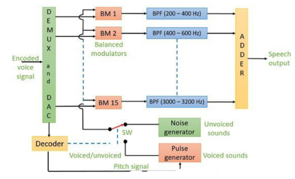
Fig 2 Voice Decoder
The signal is converted to its analog form by demux and D/A converters. The balanced modulators are used here who have carriers output of noise generator or pulse generator depending on position of the switch. When signal is unvoiced switch connects to noise generator. The adder produces the final output speech signal.
Key takeaway
This technique leads to deprivation of speech value.
- LPC-10, FIPS Pub 137, 2400 bit/s, which uses linear predictive coding
- Code-excited linear prediction (CELP), 2400 and 4800 bit/s, Federal Standard 1016, used in STU-III
- Continuously variable slope delta modulation (CVSD), 16 kbit/s, used in wide band encryptors such as the KY-57.
- Mixed-excitation linear prediction (MELP), MIL STD 3005, 2400 bit/s, used in the Future Narrowband Digital Terminal FNBDT, NSA's 21st century secure telephone.
- Adaptive Differential Pulse Code Modulation (ADP
Key takeaway
This technique leads to deprivation of speech value.

Fig 3: General spread spectrum structure
- Spread spectrum is specially used for wireless communication signal spreading. Transmitted signals frequency varies deliberately.
- Frequency hopping and direct sequence are two popular spread spectrums.
In frequency hopping, signals are broadcast over any random series of frequency while in direct sequence each bit is in order of multiple bits of transmitting signal it uses chipping code.
- Pseudo-Noise (PN) also known Pseudo Random Binary Sequence (PRBS).
- A Pseudo-Noise code (PN-code) or Pseudo Random Noise Code (PRN code) is a spectrum which generated deterministically by random sequence.
- PN sequence is random occurrence of 0’s and 1’s bit stream.
- Directly sequence spread spectrum (DS-SS) system is most popular sequence in DS-SS system bits of PN sequence is known as chips and inverse of its period is known as chip rate.
- In frequency hopping spread spectrum (FH-SS) sequence, channel number are pseudo random sequences and hop rate are inverse of its period.
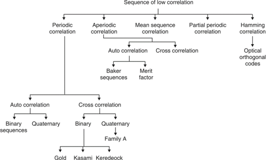
Fig. 4: Overview of PN sequence
- Properties
(i)Balance property:
Total no. Of 1’s is more than no. Of 0’s in maximum length sequence.
(ii)Run property 1’s and 0’s stream shows length sequence, every fraction relates some meaning.
Rum | Length |
1/2 | 1 |
1/4 | 2 |
1/8 | 3 |
(iii)Correlation property:
If compared sequences are found similar then it is autocorrelation.
If compared sequences are found mismatched then it is cross correlation.
Let (K) and y (K) are two sequences then correlation R (m) will be:
R (m)xy= x (k) y (k + m)
Correlation R (m) in pattern of digital bit sequence will be:
R (m)=
y1=P1 q1
y1=0 if P1 q1
y1=1 if P1 = q1
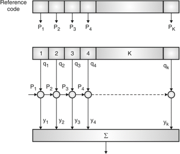
Fig. 5: Correlator
Fig5. Shows Pi is a sequence which shifts through K bit shift register. K is length of correlate. Output achieved by K XNOR gate after comparison.
(iv)Shift and add:
By using X-OR gate, shift sequence modulo-2 added to upshifted sequence.
PN sequence generation methodologies:
(i)Using shift register with feedback.
(ii)Series parallel method for high speed PN generation.
(iii)Avoiding zero state.
(iv)Barker sequence.
(v)Kasami sequence.
(vi)Gold sequence.
Key takeaway
The codes must have a sharp (1-chip wide) autocorrelation peak to enable code synchronization. · The codes must have a low cross-correlation value
Frequency Hoping Spread Spectrum (FHSS)

Fig 6: Channel assignment
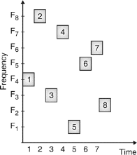
Fig.7: Channel use
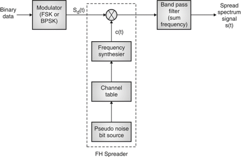
Fig.8: FHSS (Transmitter)
In FHSS, according to PN sequence RF carries frequency used to get change.
FHSS has two types
1.Fast hopped FHSS.
2.Slow hopped FHSS.
Hopping is done with faster rate compared to bit rate in fast hopped FHSS while slow rate compared to message bit rate in slow hopped FHSS.
FHSS systems rely on changes in RF carrier frequencies which turn into burst errors.

Fig.9: FHSS (Receiver)
Direct Sequence Spread Spectrum (DSSS)

Fig.10: DSSS (Transmitter)
- Base of DSSS is key to a successful recovery of message is the knowledge about PN sequence which is used at the transmitter.
- Information bits are spread across frequency as well as time, it results by minimizing effects of interference and fading. It somehow prone to error comparably FSSS system.

Fig.11: DSSS (Receiver)
Key takeaway

3.5.1 Time Hopping Systems
The signal is divided into time frames of M slots. Only one time slot is modulated when message is transmitted. The time hopping receiver is shown below. Let Tf = frame duration, k = number of message bits in one frame and Tf = k × tm, then the width of each time slot in a frame is Tf/M with BW of 2M.
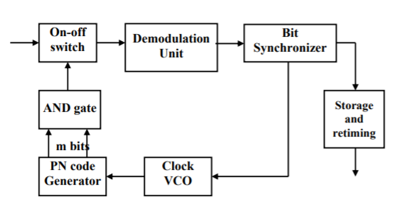
Fig 12 Time hopping receiver
The ON-OFF switch is driven by the PN generator so that proper switching takes place for the given time frame. The output from switch is demodulated. Each message burst is stored and re-timed to the original message rate in order to recover the information.
3.5.2 Hybrid Spread Systems
It is combination of DS and FH techniques. One data bit is divided into many carrier frequencies.

Fig 13 Hybrid DS-FH spreading technique
The FH-sequence and the PN-codes are coupled, a user uses a combination of an FH-sequence and a PN-code.
Key takeaway
In time hopping signal is divided into time frames of M slots. Only one time slot is modulated when message is transmitted.
The hybrid spread system is combination of DS and FH techniques.
In this type of modulation, the data stream is divided into small bits before transmission to modulate various carriers. The stream divided into bits has a lower data rate which modulates individual carriers. It was initially used in broadcasting systems.
There are various forms of MCM which were used in many fields such as OFDM was used for processing power in receivers. Later OFDM was used in wireless communication and Wi-Fi 802.11 etc.
Forms of Multicarrier Modulation System
i) OFDM: It is orthogonal frequency division multiplexing. It has multiple closely spaced carriers and due to the orthogonality between them mutual interference is avoided. It is most commonly used form of MCM.
Ii) GFDM: It is generalised frequency division multiplexing. The carriers used here are closed spaced and non-orthogonal. These carriers provide pulse shaping. They are widely used in machine-to-machine communications.
Iii) FBMC: It is called as filter bank multi carrier. This modulation uses isotropic transform algorithm within the DSP. The inter-carrier and inter-symbol interference are avoided by using this scheme.
Iv) SEFD: It is known as spectrally efficient FDM. It also uses multiple carriers but are closer than what are used in OFDM.
v) MC-CDMA: It is known as Multicarrier code division multiplexing. It is used to spread the signal over different subcarriers. Signals to different users are added linearly onto a multiplex of Multi-Carrier CDMA signals.
Key takeaway
MCM are widely used in digital transmission in telephone lines.
When few symbols interfere with the subsequent signals ISI occurs which may distort the signal. The cause if ISI is due to multipath propagation and Non-linear frequency in channels. The blow figure shows the ISI in the signals.

Fig 14 ISI on received Pulse
The Nyquist criterion to overcome ISI is called as Zero ISI. In this the pulse amplitude can be detected correctly irrespective of the signal spreading and overlapping.
The zero ISI pulse should satisfy the following condition
p(t) = 1 t=0
= 0 t=±Tb, ±2Tb, ±3Tb,……
When the pulse satisfies the given condition, it has zero ISI when received. The waveforms like square pulse of bit period Tb and triangular waveform of bit period <2Tb. The spectrum for these pulses is given below.
P(ω) =  for ω-
 <
<
= 0 for  >
>  +
+ 
= 1 for  <
<  +
+ 
 = frequency of bits
 = excess bandwidth
The pulse is shown below with the bandwidth
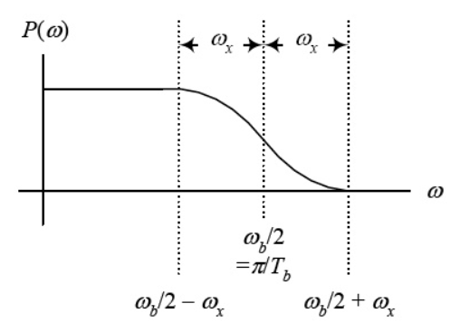
Fig 15 Spectrum of pulse
For  =0 the spectrum is rect function. For
  =
=  /2 spectrum is sinc function. The spectrum for which is shown below
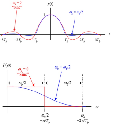
Fig 16 Spectrum of pulse
The roll-off factor r is given as r= =
= 
Key takeaway
The zero ISI pulse should satisfy the following condition
p(t) = 1 t=0
= 0 t=±Tb, ±2Tb, ±3Tb,……
If you’re a fan of the Olympics, I am sure you have watched plenty of track events – especially the exciting 400 and 800 meter relays. Four athletes run in each event and hand a baton off to the next athlete until the race is complete. Although the handoffs are usually done without mishap.
When a mobile moves into a different cell while a conversation is in progress, the MSC automatically transfers the call to a new channel belonging to the new base station. This handoff operation not only involves identifying a new base station, but also requires that the voice and control signals be allocated to channels associated with the new base station.
Three strategies have been proposed
- In mobile-controlled handoff (MCHO)
- In network-controlled handoff (NCHO)
- In mobile-assisted handoff (MAHO)
- In mobile-controlled handoff (MCHO)
The MS continuously monitors the signal of surrounding BSs and initiate the handoff process when some handoff criteria are met. MCHO is used in DECT
(Digital Enhanced Cordless Telecommunications)
2. In network-controlled handoff (NCHO)
The surroundings BSs measure the signal from the MS, 7 the network initiates the handoff process when some handoff criteria are met.
3. In mobile-assisted handoff (MAHO)
The network asks the MS to measure the signal from the surrounding BSs. The network makes the handoff decision based on report from the MS. MAHO is used in GSM & IS-95 CDMA
Inter-BS Handoff
In inter-BS handoff, the new & old BSs are connected to same MSC. Assume that the need for handoff is detected by the MS therefor the following actions are to be considered.
- The MS temporarily suspend conversation & initiates the handoff procedure by signalling on free channel in new BS. Then it resumes the conversation on the old BS. As in fig below.
- Upon receipt of the signal, the MCS transfer the encryption information to the selected idle channel of the new BS & set up the new conversation path to the MS through that channel.as in fig below
- After the MS has been transferred to the new BS, it signals the network and resume conversation using the new channel. Upon receipt of the handoff completion signal the network removes the bridge from the path and release resources associated with the old channel as in fig below.
- This handoff procedure is used with mobile controlled handoff strategy. For network-controlled handoff signalling messages are exchanged between the MS & old BS through the falling link. The whole process is completed as quickly as possible to ensure that new link
Key takeaway
This handoff operation not only involves identifying a new base station, but also requires that the voice and control signals be allocated to channels associated with the new base station.
When there are multiple antennas there are different propagation paths. SO, same data can be transmitted along different paths and this is called as spatial diversity.
When we try to improve the data rate by placing different portions of data on different propagation paths is spatial multiplexing.
MIMO system with Diversity
In this case same information is passed on through different fading channels. The amount of fade experienced by each data will differ as same data is passed through different channels. Hence, the due to many copies of same signal being transmitted increases the chance of properly receiving the data. This reduces the co-channel interference. By adding more antennas at transmitter and receiver more diversity paths can be created. The 2x2 MIMO system is shown below.
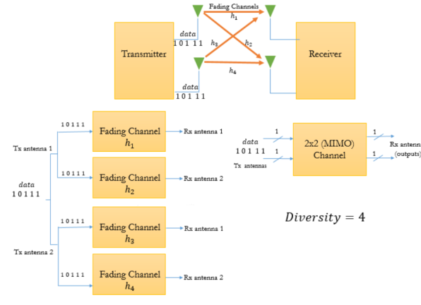
Fig 17 MIMO system with diversity
Spatial Multiplexing with MIMO
In this case each channel carries independent information which increases the data rate. It has some similarities with OFDM. Here each bit of data stream is multiplexed on three different channels as shown below. This increases the data rate. The diversity gain is zero and multiplexing gain is 3 as we are taking 3x3 MIMO.
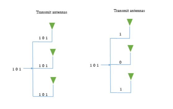
Fig 18 MIMO system with diversity MIMO with spatial multiplexing
Key takeaway
When there are multiple antennas there are different propagation paths. SO, same data can be transmitted along different paths and this is called as spatial diversity.
When we try to improve the data rate by placing different portions of data on different propagation paths is spatial multiplexing.
When there are multiple antennas there are different propagation paths. SO, same data can be transmitted along different paths and this is called as spatial diversity.
When we try to improve the data rate by placing different portions of data on different propagation paths is spatial multiplexing.
MIMO system with Diversity
In this case same information is passed on through different fading channels. The amount of fade experienced by each data will differ as same data is passed through different channels. Hence, the due to many copies of same signal being transmitted increases the chance of properly receiving the data. This reduces the co-channel interference. By adding more antennas at transmitter and receiver more diversity paths can be created. The 2x2 MIMO system is shown below.
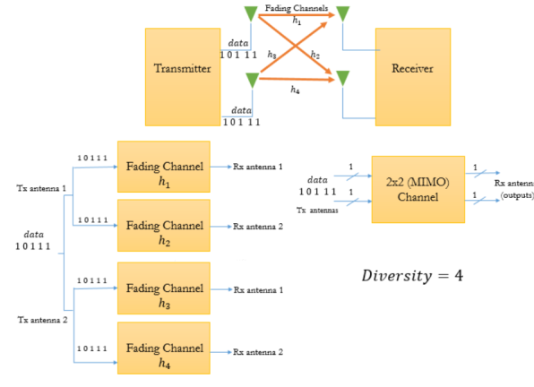
Fig 19 MIMO system with diversity
Spatial Multiplexing with MIMO
In this case each channel carries independent information which increases the data rate. It has some similarities with OFDM. Here each bit of data stream is multiplexed on three different channels as shown below. This increases the data rate. The diversity gain is zero and multiplexing gain is 3 as we are taking 3x3 MIMO.
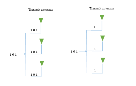
Fig 20 MIMO system with diversity MIMO with spatial multiplexing
Key takeaway
When there are multiple antennas there are different propagation paths. SO, same data can be transmitted along different paths and this is called as spatial diversity.
When we try to improve the data rate by placing different portions of data on different propagation paths is spatial multiplexing.
The channel estimation can be done for narrow band signals in wireless communication. The transmission is through radio channels. For conventional, coherent receivers, the effect of the channel on the transmitted signal must be estimated to recover the transmitted information. For example, with binary phase shift keying (BPSK), binary information is represented as +1 and −1 symbol values. The radio channel can apply a phase shift to the transmitted symbols, possibly inverting the symbol values.
The transmitted signals are reflected, scattered and due to fading it is difficult to estimate the channel in wireless systems. For narrow band signals the digital symbol transmitted are
X(t) = 
The estimation of the channel can be done by
Linear interpolation
This is the simplest of all techniques. The channel is estimated by combining two nearest signals for channel measurement. The estimation at time k and 0<k<M is given by
 =ak(0)
 + ak(1)
ak(0) = M-k/M
ak(1) = k/M
Linear interpolation can be viewed as applying a filter with symbol‐spaced taps to the channel measurements, which contain zeros at the unknown data symbol points.
Weiner Filtering
The channel function for estimation is given as
 =akT
=akT
ak = Nmx1 vector of interpolation coefficients
ak =  pk
pk
 = autocorrelation matrix of channel.
pk = cross-correlation vector between channel at pilot cluster and channel at time k
3.13.1 Transversal Filters
The equalization filter which uses delay lines with T-second taps to generate set of cancelling echoes. Let us consider a single pulse was transmitted. The system has a cosine transfer function. Let the transfer function be
HRC(t) = Ht(f). Hr(f)
So, if the channel induces ISI the signal at the receiving end will have distortion. In order to get desired output, we need to have the frequency response as
He(f) = 1/Hc(f) = 1/|Hc(f)|e-j
The transversal filter is shown below. The tab value can be selected such that the impulse response can be forced to zero.
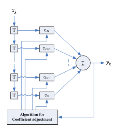
Fig 21 Transversal Filter
Let there be 2N+1 tab and each having delay of C-N, C-N+1…… The sample at output is convolution of input and the tab weights Cn
Z(k)= for k= -2N …2N
Key takeaway
For zero forcing equalizer Z(k)=
Z(k)= 1 for k=0
= 0 for k= ±1……,±N
For Mean square equalizer the taps are adjusted in such a way that MSE of ISI and noise power at equalizer output are minimized.
3.13.2 Adaptive Equalizers
An equalizer is used to track time varying property of the mobile channel. Due to the randomness and time varying property of fading it is necessary to have an equalizer.
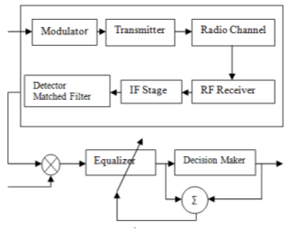
Fig 22 Adaptive Equalizer
Let s(t) be the original signal and signal f(t) is the combined response of channel, transmitter and IF/RF section of receiver. The signal at the input of the equalizer is
x(t) = s(t) f*(t)+nb(t)
The output of equalizer is
y(t) = x(t) heq(t)
Let g(t) be combined response of channel, transmitter and IF/RF section of receiver then above equation becomes
Y(t) = h(t) g(t) +nb(t)
 heq(t)
The impulse response of the equalizer transversal filter is given by
heq(t) = 
The output of equalizer needs to be equal to the original signal s(t).
y(t)= s(t) f*(t)
f*(t) heq(t)+nb(t)
 heq(t)
g(t)= f*(t) heq(t) =
 (t)
(t)
The following equation should be fulfilled
Heq(f)F*(-f) = 1
Where:
f*(t) = complex conjugate f(t)
heq(t) = equalizer impulse response
nb(t) = noise of baseband
Cn= complex coefficients of filter
Heq(f)= Fourier Transform of heq(t)
Key takeaway
In order to nullify the effect of Inter symbol interference (ISI) at the receiver side, equalization techniques are used. The main function of the equalizer is to reconstruct the actual signal with the help of channel response and estimated signal.
3.13.3 Zero Forcing Equalizers
In this type of equalisation technique, the output at the equalizer is forced to zero. This output is forced to zero using linear time invariant filter having proper transfer function. The received symbol on the first receiver is given by
y1= h11x1+h12x2+n1
= [h11 h12]  + n1
+ n1
The received symbol on second receiver is given by
y2= h21x1+h22x2+n2
= [h21 h22]  + n2
+ n2
The matrix for above two will be
 =
=  +
+ 
x1, x2 = transmitted symbols
h11 = Channel between first transmitter and first receiver
h12 = Channel between second transmitter and first receiver
h21= Channel between first transmitter and second receiver
h22 = Channel between second transmitter and second receiver
The matrix form can be written as
y= Hx + n
Let W be the inverse matrix of H
WH = I
The matrix W is called as zero forcing linear detector if it satisfies the above condition.
W = (HHH)-1HH
HH = 
The zero-forcing equalizer cancel out the interference signal as the off-diagonal terms are non-zero.
Key takeaway
This method has a setback that it amplifies the noise and the output is distorted.
3.13.4 Decision Feedback Equalizers
To overcome the drawback of linear filter decision feedback equalizers are used. The linear filters can introduce noise variance at output and to overcome this we use decision feedback equalizers. These equalizers can predict the noise based on the previous noise samples. The predicted noise is than subtracted from the input by feedback filter. This over all reduces the noise level of the signal.

Fig 23 Decision feedback equalizer
Key takeaway
The feedback filter reduces the noise.
Reference:
1. T.S. Rappaport, “Wireless Communication-Principles and practice”, Pearson
Publications, Second Edition.
2. Misra, Wireless Communication & Network: 3G & Beyond, McGraw Hill Education
3. Jaganathan, Principles of Modern Wireless Communication System, McGraw Hill Education
4. Upena Dalal, “Wireless Communication and Networks”, Oxford Press Publications.
5. T L Singal, “Wireless Communications”, McGraw Hill Education.