Unit 1
Digital Principle
Key Takeaways:
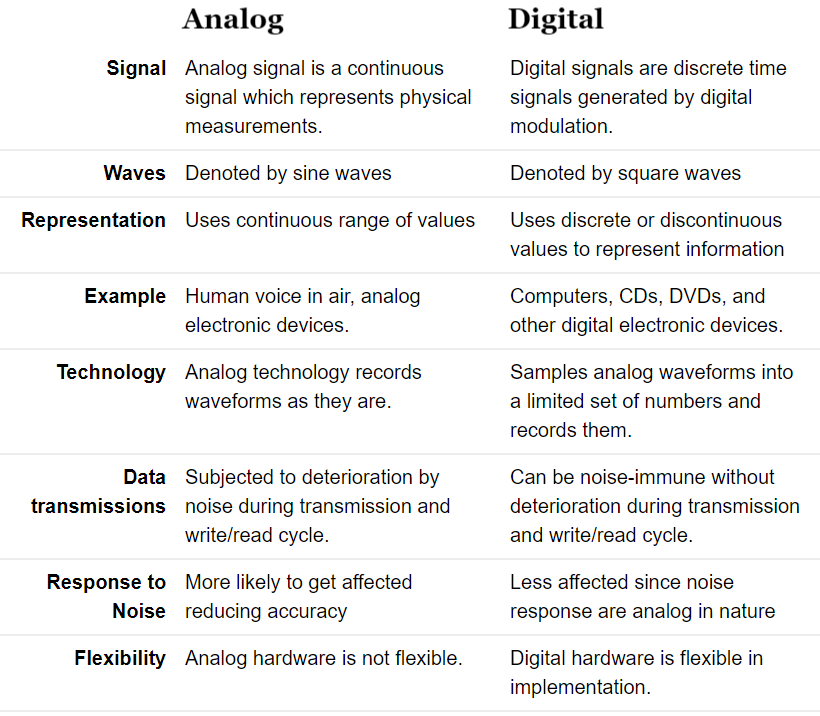
Analog signals are used for analog communication and digital signals for digital communication.
Analog signals are used for long distance communication while digital communication for short distance.
A digital system understands positional number system where there are few symbols called digits and this symbol represents different values depending on their position in the number.
A value of the digit is determined by using
- The digit
- Its position
- The base of the number system
Decimal Number System
- Its the system that we use in our daily life. It has a base 10 and uses 10 digits from 0 to 9.
- Here, the successive positions towards the left of the decimal point represent units, tens, hundreds, thousands and so on.
- Each and every position represents a specific power of the base (10). For example, the decimal number 4321 consists of the digit 1 in the units position, 2 in the tens position, 3 in the hundreds position, and 4 in the thousands position, and its value can be written as
(1×1000) + (2×100) + (3×10) + (4×l)
(1×10³) + (2×10²) + (3×101) + (4×l00)
1000 + 200 + 30 + 1
1234
- As a computer programmer, we should understand the following number systems used in computers.
S.N. | Number System & Description |
1 | Binary Number System Base 2. Digits used: 0 and 1 |
2 | Octal Number System Base 8. Digits used: 0 to 7 |
3 | Hexa Decimal Number System Base 16. Digits used: 0 to 9, Letters used: A- F |
Binary Number System
- It uses two digits 0 and 1.
- It is also called as base 2 number system.
- Here, each position in any binary number represents a power of the base (2). Example: 23
- The last position represents a y power of the base (2). Example: 2y where y represents the last position.
Example
Binary Number: 101112
Calculating the Decimal Equivalent of binary number −
Step | Binary Number | Decimal Number |
Step 1 | 101012 | ((1 × 24) + (0 × 23) + (1 × 22) + (1 × 21) + (1 × 20))10 |
Step 2 | 101012 | (16 + 0 + 4 + 2 + 1)10 |
Step 3 | 101012 | 2310 |
Note: 101112 is normally written as 10111.
Octal Number System
- It consists of eight digits 0, 1,2,3,4,5,6,7.
- It is also named as base 8 number system.
- Here each position represents a power of the base (8). Example: 82
- The last position represents a y power of the base (8). Example: 8y where y represents the last position .
Example
Octal Number − 125758
Calculating Decimal Equivalent −
Step | Octal Number | Decimal Number |
Step 1 | 125758 | ((1 × 84) + (2 × 83) + (5 × 82) + (7 × 81) + (5 × 80))10 |
Step 2 | 125758 | (4096 + 1024 + 320 + 56 + 5)10 |
Step 3 | 125758 | 550010 |
Note: 125758 is normally written as 12575 in octal.
Hexadecimal Number System
- It uses 10 digits starting from 0,1,2,3,4,5,6,7,8,9 and 6 letters A,B,C,D,E,F.
- These letters represents numbers as A = 10, B = 11, C = 12, D = 13, E = 14, F = 15.
- It is also known as base 16 number system.
- Here each position represents a power of the base (16). Example 161.
- The last position represents a y power of the base (16). Example: 16y where y represents the last position .
Example −
Hexadecimal Number: 19FDA16
Calculating Decimal Equivalent −
Step | Hexadecimal Number | Decimal Number |
Step 1 | 19FDA16 | ((1 × 164) + (9 × 163) + (F × 162) + (D × 161) + (A × 160))10 |
Step 2 | 19FDA16 | ((1 × 164) + (9 × 163) + (15 × 162) + (13 × 161) + (10 × 160))10 |
Step 3 | 19FDA16 | (65536 + 36864 + 3840 + 208 + 10)10 |
Step 4 | 19FDA16 | 10645810 |
Note − 19FDA16 is normally written as 19FDA in hexa decimal.
Key Takeaways:
Binary number system: 0 and 1
Decimal number system: 0 to 9
Octal number system: 0 to 7
Hexa Decimal number system: 0 to 9 and A to F
- In coding, when alpha-numeric characters or words are represented by a specific group of symbols, it is said that it is being coded.
- The group of symbols is known as a code.
- The digital data can be represented, stored and transmitted as group of binary bits.
- This group is called as binary code.
- It is represented by the number as well as alphanumeric character.
Advantages of Binary Code
- They are used in computer applications.
- They are suitable for digital communications.
- They make the analysis and designing of digital circuits easy.
- Implementation becomes very easy since only 0 & 1 are being used.
Classification of binary codes
The codes are broadly classified as:
- Weighted Codes
- Non-Weighted Codes
- Binary Coded Decimal Code
- Alphanumeric Codes
- Error Detecting Codes
- Error Correcting Codes
Weighted Codes
- These codes obey the positional weight principle.
- Here each position represents a specific weight.
- Several systems are used to express the decimal digits 0 through 9.
- Here, each decimal digit is represented by a set of four bits.
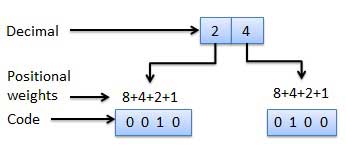
Fig.: Weighted codes (Ref. 1)
Non-Weighted Codes
- Here, the positional weights are not assigned.
- Example: Excess-3 code and Gray code.
- Excess-3 code
- It is also known as XS-3 code.
- It is a non-weighted code used to express decimal numbers.
- They are derived from the 8421 BCD code words adding (0011)2 or (3)10 to each code word in 8421.
- The excess-3 codes are obtained as −

Example
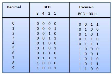
Fig.: BCD to XS 3 conversion (Ref. 1)
2. Gray Code
- It is the non-weighted code and is not an arithmetic code.
- This means that there are no specific weights assigned to the bit position.
- Here only one bit will change every time the decimal number is incremented .
- The gray code is also known as a unit distance code as only one bit changes at a time.
- The gray code is a type of cyclic code.
- It cannot be used for all arithmetic operation.
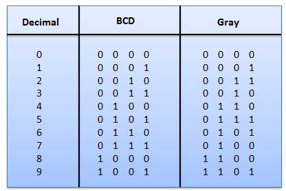
Fig.: Gray codes (Ref. 1)
Application of Gray code
- They are used in the shaft position encoders.
- This encoder produces a code word which represents the angular position of the shaft.
3. Binary Coded Decimal (BCD) code
- Here each decimal digit is represented by a 4-bit binary number.
- Its a way to express each of the decimal digits with a binary code.
- Therefore, by four bits we can represent sixteen numbers (0000 to 1111).
- But in BCD code only first ten of these numbers are used (0000 to 1001) and rest are invalid.

Fig.: BCD codes (Ref. 1)
Advantages of BCD Codes
- It is very similar to decimal system.
- We have to remember binary equivalent of 0 to 9 only.
Disadvantages of BCD Codes
- The addition and subtraction of BCD number system have different rules.
- The BCD arithmetic is more complicated.
- BCD code requires more number of bits than binary code to represent the decimal number.
- Hence is less efficient than binary.
4. Alphanumeric codes
A binary digit or bit can be represented by two symbols as '0' or '1'.
This is not sufficient for communication between two computers as we need many more symbols for communication.
These symbols are represents 26 alphabetic characters with capital and small letters, numbers from 0 to 9, punctuation marks and other symbols.
These alphanumeric codes represent numbers and alphabetic characters.
Most of them also represent other characters like symbol and various instructions necessary for conveying information.
The code at least represents 10 digits and 26 letters of alphabet i.e. total 36 items.
The following three types of alphanumeric codes are commonly used for the data representation.
- American Standard Code for Information Interchange (ASCII).
- Extended Binary Coded Decimal Interchange Code (EBCDIC).
- Five bit Baudot Code.
ASCII code is a 7-bit code whereas EBCDIC is an 8-bit code.
ASCII code is used worldwide while EBCDIC is primarily used in large IBM computers.
5.Error Codes
There technique is available to detect and correct data during data transmission.
Error Code | Description |
Error Detection and Correction | Error detection and correction code techniques |
Key Takeaways:
Alpha-numeric characters or words are represented by a specific group of symbols, it is said that it is being coded.
The digital data can be represented, stored and transmitted as group of binary bits.
- Computers are digital in nature.
- They process, store, and communicate information in binary form which is the combination of 1s and 0s.
- A bit is an individual 1 or O.
- Multiple bit streams are used in a computer network.
- Here, signal varies in voltage to positive (+) voltage and a null or zero (0) voltage (unipolar) or a positive (+) or a negative (-) voltage (bipolar).
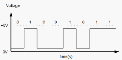
Fig: Digital signal
In this a high level H is represented for logic 1 and a low level L is represented for logic 0.

Fig: Waveform
- Digital electronic circuits operate at two logic levels namely Logic Low and Logic High.
- The Logic Low is represented with ‘0’and Logic High is represented with ‘1’.
- The basic digital electronic circuit which has one or more inputs and single output is known as Logic gate.
- These Logic gates are known as the building blocks of any digital system. They can classified as:
Basic gates
Universal gates
Special gates
Basic Gates
The basic gates are namely AND gate, OR gate & NOT gate.
AND gate
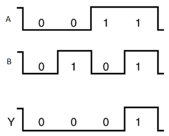
It is a digital circuit that consists of two or more inputs and a single output which is the logical AND of all those inputs. It is represented with the symbol ‘.’.
The following is the truth table of 2-input AND gate.
A | B | Y = A.B |
0 | 0 | 0 |
0 | 1 | 0 |
1 | 0 | 0 |
1 | 1 | 1 |
Here A, B are the inputs and Y is the output of two input AND gate.
If both inputs are ‘1’, then only the output, Y is ‘1’. For remaining combinations of inputs, the output, Y is ‘0’.
The figure below shows the symbol of an AND gate, which is having two inputs A, B and one output, Y.

Fig. : AND gate (ref. 1)
Timing Diagram:
OR gate
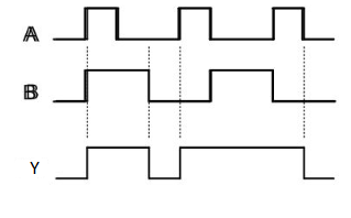
It is a digital circuit which has two or more inputs and a single output which is the logical OR of all those inputs. It is represented with the symbol ‘+’.
The truth table of 2-input OR gate is:
A | B | Y = A + B |
0 | 0 | 0 |
0 | 1 | 1 |
1 | 0 | 1 |
1 | 1 | 1 |
Here A, B are the inputs and Y is the output of two input OR gate.
When both inputs are ‘0’, then only the output, Y is ‘0’. For remaining combinations of inputs, the output, Y is ‘1’.
The figure below shows the symbol of an OR gate, which is having two inputs A, B and one output, Y.

Fig. : OR gate (ref. 1)
Timing Diagram:
NOT gate
It is a digital circuit that has one input and one output. Here the output is the logical inversion of input. Hence, it is also called as an inverter.
The truth table of NOT gate is:
A | Y = A’ |
0 | 1 |
1 | 0 |
Here A and Y are the corresponding input and output of NOT gate. When A is ‘0’, then, Y is ‘1’. Similarly, when, A is ‘1’, then, Y is ‘0’.
The figure below shows the symbol of NOT gate, which has one input, A and one output, Y.
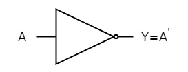
Fig. : NOT gate (ref. 1)
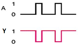
Timing Diagram:
Universal gates
NAND & NOR gates are known as universal gates.
We can implement any Boolean function by using NAND gates and NOR gates alone.
NAND gate
It is a digital circuit which has two or more inputs and single output and it is the inversion of logical AND gate.
The truth table of 2-input NAND gate is:
A | B | Y = (A.B)’ |
0 | 0 | 1 |
0 | 1 | 1 |
1 | 0 | 1 |
1 | 1 | 0 |
Here A, B are the inputs and Y is the output of two input NAND gate. When both inputs are ‘1’, then the output, Y is ‘0’. If at least one of the input is zero, then the output, Y is ‘1’. This is just the inverse of AND operation.
The image shows the symbol of NAND gate:

Fig.: NAND gate (ref. 1)
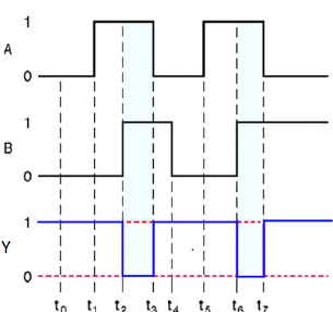
NAND gate works same as AND gate followed by an inverter.
Timing Diagram:
NOR gate
It is a digital circuit that has two or more inputs and a single output which is the inversion of logical OR of all inputs.
The truth table of 2-input NOR gate is:
A | B | Y = (A+B)’ |
0 | 0 | 1 |
0 | 1 | 0 |
1 | 0 | 0 |
1 | 1 | 0 |
Here A and B are the two inputs and Y is the output. If both inputs are ‘0’, then the output is ‘1’. If any one of the input is ‘1’, then the output is ‘0’. This is exactly opposite to two input OR gate operation.
The symbol of NOR gate is:

Fig.: NOR gate (ref. 1)
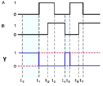
NOR gate works exactly same as that of OR gate followed by an inverter.
Timing Diagram:
Special Gates
Ex-OR gate
It stands for Exclusive-OR gate. Its function varies when the inputs have even number of ones.
The truth table of 2-input Ex-OR gate is:
A | B | Y = A⊕B |
0 | 0 | 0 |
0 | 1 | 1 |
1 | 0 | 1 |
1 | 1 | 0 |
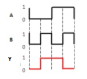
Here A, B are the inputs and Y is the output of two input Ex-OR gate. The output (Y) is zero instead of one when both the inputs are one.
Therefore, the output of Ex-OR gate is ‘1’, when only one of the two inputs is ‘1’. And it is zero, when both inputs are same.
The symbol of Ex-OR gate is as follows:
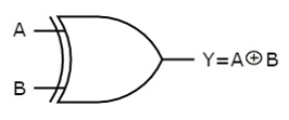
Fig.: XOR gate (ref. 1)
It is similar to that of OR gate with an exception for few combination(s) of inputs. Hence, the output is also known as an odd function.
Timing Diagram:
Ex-NOR gate
It stands for Exclusive-NOR gate. Its function is same as that of NOR gate except when the inputs having even number of ones.
The truth table of 2-input Ex-NOR gate is:
A | B | Y = A⊙B |
0 | 0 | 1 |
0 | 1 | 0 |
1 | 0 | 0 |
1 | 1 | 1 |
Here A, B are the inputs and Y is the output. It is same as Ex-NOR gate with the only modification in the fourth row. The output is 1 instead of 0, when both the inputs are one.
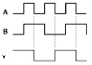
Hence the output of Ex-NOR gate is ‘1’, when both inputs are same and 0, when both the inputs are different.
The symbol of Ex-NOR gate is:
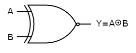
Fig.: XNOR gate (ref. 1)
It is similar to NOR gate except for few combination(s) of inputs. Here the output is ‘1’, when even number of 1 is present at the inputs. Hence is also called as an even function.
Timing Diagram:
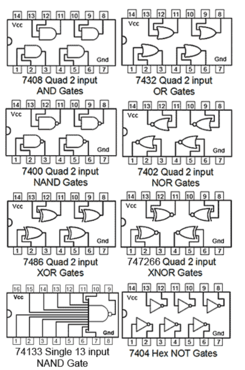
IC’s OF ALL GATES
Key Takeaways:
Basic Gates: AND, OR, NOT
Universal Gates: NAND, NOR
Special Gates: XOR, XNOR
Reference Books:-
1) “Digital Fundamentals”, Floyd and Jain, Pearson
2) “Digital Logic and Computer design”, M. Morris Mano, Pearson
3) “Fundamentals of Digitals Circuits”, A. Anand Kumar, PHI
4) “Digital Systems”, Ronald J. Tocci, Neal S. Widmer, Pearson