Unit 5
Timing circuit
Multivibrators are sequential logic circuits that operate continuously between HIGH and LOW.
There are three types of clock pulse generation circuits:
- Astable – It has NO stable states but switches continuously between two states. This action results in a train of square wave pulses at a fixed frequency.
- Monostable – It has only ONE stable state and is triggered externally with it thus returning back to its first stable state.
- Bistable – It has TWO stable states that produces a single pulse either positive or negative.
Monostable Multivibrators or “one-shot” pulse generators are often used to convert short sharp pulses into wider ones for timing applications. They generate a single output pulse when a suitable external trigger signal or pulse T is applied.
Astable Multivibrators are the most commonly used multivibrator circuit. It is a free running oscillator that have no permanent state but are continually changing there output from (LOW) to (HIGH) and then back again. This continuous switching action produces a continuous and stable square wave output that switches abruptly between the two logic levels making it ideal for timing and clock pulse applications.
Features:
- It operates from +5 Volts to +18 Volts supply voltage.
- Sinking or sourcing 200 mA of load current.
- The duty cycle is adjustable.
- The maximum power dissipation per package is 600 mW.
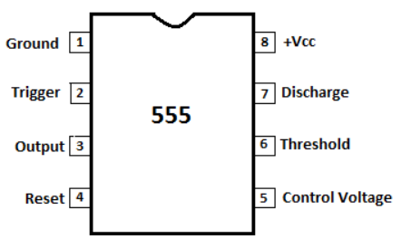
Pin Diagram:

Fig.1:Pin Diag of LM555
- TRIG: It is an input pin. Output of the timer depends upon the amplitude of the external trigger voltage.
- OUT: This output is approximately 1.7 V below +Vcc.
- RESET: The timer does not start until RESET rises above approximately 0.7 volts. Overrides TRIG which overrides threshold.
- THR: The timing (OUT high) interval ends when the voltage at threshold is greater than that at CTRL.
- DIS: In phase with output, Open collector output may discharge a capacitor between intervals.
Working:
The 555 timer operates in 3 modes:
- A-stable
- Mono-stable
- Bi-stable modes.
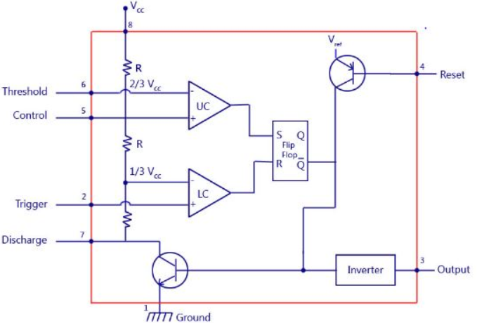
Block Diagram:
Fig.2:Block Diag of LM555
Reference Books:-
1) “Digital Fundamentals”, Floyd and Jain, Pearson
2) “Digital Logic and Computer design”, M. Morris Mano, Pearson
3) “Fundamentals of Digitals Circuits”, A. Anand Kumar, PHI
4) “Digital Systems”, Ronald J. Tocci, Neal S. Widmer, Pearson