UNIT 4
Dielectric behavior of materials
When an insulating material is positioned in an electric field the electrons are displaced with reverence to their nuclei and every atom behaves like an atomic dipole. When these atomic dipoles are formed the material is said to be polarized. If the field is detached the atoms get in touch with their regular state called unpolarized state that is the dipole formation disappears.
Polarization in Vacuum

Fig.4.1
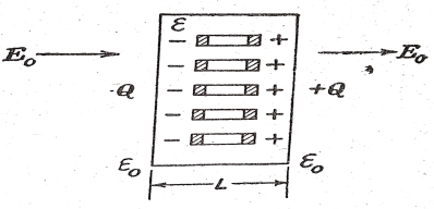
Let a material of permittivity ε, positioned in a vacuum and having an identical field  normal to a slab of dielectric material. This polarizes the dielectric inductor atomic dipoles all over the slab. In the inner part the +ve and –ve charges of neighboring dipole cancel each other’s result, the net outcome of polarization is to generate a layer of negative charge on one surface of the slab and layer of positive charge on other.
The effect of the atomic dipole is explained by the parameter P called Polarization (dipole moment per unit volume)
P =  L/V …… (1)
V= Volume of material =AL
A=Area & L=Length of specimen
 = charge on area A of one face of volume V.
P =  =
=  …….. (2)
Hence polarization has dimensions of
(i) Dipole moment per unit volume
(ii) Charge per unit area
Thus P = 
=  that is surface charge density …….. (3)
The value of polarization can be said as
P =  L/V
L/V
To describe the meaning of polarization at a point assuming that there is an unbroken division of dipoles. The value of polarization at a point can be defined as the net dipole moment  L of a small volume ΔV divided by the volume with the limit taken ΔV shrinks to zero.
P =  L/ΔV =
  L/ΔV …… (4)
 Lim ΔV 0
The relation between flux density and polarization
In any insulating material, the flux density D is associated with Polarization P by

Fig.4.2
D =  E + P …….. (5)
Where  is the permittivity of vacuum
E is the field in the material
D = ( +
+  ) E ……..(6)
Comparing the equation we get
D = ε E
ε = ( +
+  ) =
) =  +
+ ………(7)
ε is the permittivity of insulating material
 =
= 
 is electrical susceptibility. The permittivity in terms of electrical susceptibility is given by
ε =  …………. (8)
The flux density D is normal to the slab of the material face is the same as in the vacuum, that is D is normal to slab and vacuum both.

P=  -E) …….. (9)
 Field in vacuum
E = Field in dielectric
The polarization P equals the difference between applied and resultant fields multiplied by  The difference is due to the induced field
  opposing
  which produced by the polarization charge on the slab surfaces. Thus E = (
 ……. (10)
From definition
P = 
P = - …..(11)
In a conductor, the induced field equals the applied field so that the resultant field is zero on the other hand in a dielectric the induced field  is always less than the applied field
  so that resultant E is not zero.
P =  - 1) E …….. (12)
Dielectric constant (  ) is defined as the ratio of electric permeability of the material to electric permeability of free space. Its value can be defined as the ratio of capacitance formed by two plates with material between them to the capacitance of the same plates with air as dielectric.
The dielectric constant is the fraction of the capacitance created by two plates with a material linking them to the capacitance of the matching plates with air as the dielectric. For low megahertz, frequencies are of a lesser amount equal to 1,000 MHz. For high megahertz, frequencies are larger than 1,000 MHz.
Insulating materials are used in two ways: to insulate and support components of an electric system from each other and the ground, and to function as the dielectric of a capacitor. Low dielectric constant values are chosen for high frequency or power applications to reduce electric power loss. High values of dielectric constant are suggested for capacitance applications of small sizes.
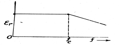
In case of dipole polarization, if we enlarge the frequency of a.c voltage the permittivity of a dipole material at first is constant but decreases with the enhancing of frequency initiating from the critical frequency , when the polarization already does not have time wholly set for one-half periods. The critical frequency
 is given by the relation.

Fig.4.3
 =
=  …… (1)
K= Boltzmann’s constant
T = Absolute Temperature
V= Molecule volume
r = radius of molecule
On heating, a dielectric material in a varying electric field loss of energy occurs which is termed as dielectric loss, For example, a capacitor integrated with an alternating-current circuit is alternately charged and discharged each half cycle. During the rotation of polarity of the plates, the charges must be displaced through the dielectric first in one direction and then in the other, and overcoming the opposition that they meet to the creation of heat through dielectric loss, a quality that must be measured when applying capacitors to electric circuits, such as those in radio and television receivers.
It can be parameterized in terms of loss tangent tan δ. Let us consider an a.c field
e =  cosωt
cosωt
Where  is maximum value
If this field is applied for considerable time t the electric flux density D. We know that D will be not in phase with E, an angle called a phase shift.
Hence D =  cos(ωt – φ)
D =  cos φcos ωt +
  sin φsin ωt
D =  cos ωt +
  sin ωt
Where  =
=  cos φ
cos φ
Cos φ,  =
=  sin φ
sin φ
Tan φ =  ……(1)
……(1)
For most materials  will be proportional to
  and
and  the ratio depends on the frequency. Therefore two different permittivities
  and
and  frequency variants are introduced.
 =
=  …..(2)
 =
=  …..(3)
From equation (1) tan φ =  =
=  =
=  …….(4)
 + j
+ j =
=  cos φ +
  sin φ
sin φ
 =
=  +j
+j 
Tan δ =  =
=  ………(5)
 = tan δ
 …….(6)
 cos δ,
  sin δ
sin δ
 + j
+ j =
=  cos δ +
  sin δ =
  +j
+j 
Also tan δ =  =
= 
Certain solid materials accumulate electric charge (such as crystals, certain ceramics, and biological matter for example bone, DNA, and different proteins) in reaction to applied mechanical stress is termed as Piezoelectricity. The word piezoelectricity means electricity follow-on from pressure and latent heat. It is originated from the Greek word piezein, which means to squeeze or press, and ēlektron, which means amber, a prehistoric basis of electric charge. French physicists Jacques and Pierre Curie revealed piezoelectricity in 1880.
Piezoelectricity is broken in many constructive applications, such as the production and recognition of sound, piezoelectric inkjet printing, production of high voltages, electronic frequency production, microbalances, to drive an ultrasonic nozzle, and ultrafine focusing of optical assemblies. The scanning probe microscopies, such as STM, AFM, MTA, and SNOM.
The piezoelectric effect is the alter of polarization P when applying mechanical stress. Under the influence of the external stress by re-orientation of molecular dipole moments shows the piezoelectric effect. The dissimilarity of the polarization strength may be marked as Piezoelectricity with the information depending on the direction of P within the crystal; crystal symmetry; and the applied mechanical stress. A variation of surface charge density upon the crystal faces appears as a change in P.
On the application of an external electric field in a certain material, a spontaneous polarization that can be reversed is having a ferroelectric behavior. The entire ferroelectrics are pyroelectric, with the added property that their expected electrical polarization is reversible. The word is used in similarity to ferromagnetism, in which a material exhibits an unending magnetic moment. Ferromagnetism was known when ferroelectricity was discovered in 1920 in Rochelle salt by Valasek. Thus, the prefix Ferro, meaning iron, was used to explain the property even though most ferroelectric materials do not contain iron.
Ferroelectric materials can be used to make capacitors, ferroelectric RAM for computers and RFID cards, energy harvester.
Reference
i) Electrical Engineering Materials, Dr. G.P. CHHALOTRA & Dr. B.K.BHAT, Khanna Technical Publications