UNIT 5
Magnetic Properties
Magnetism in Metallic Material
The magnetism of solid is originated from the electrons of atoms. Electrons are making orbital motions and spin rotations. Since an electron has a charge, magnetic moment appears just like magnetic filed is generated when current flows in solenoid coils. The magnetic moment appears even from the spin orientation of electrons. The magnetic moment generated from the orbital or spin motion of a single electron is called Bohr magnetron, which is the smallest unit of magnetic moment of solids.
Although many electrons are moving by orbital motions and spin orientations around a nuclei, only two electrons with up and down spins can occupy one orbit. Therefore, most of the magnetic moments originated from spins cancel each other and does not contribute to the magnetic moment of a solid. In the case of transition elements whose d-orbit is not fully occupied and rare earth elements whose p-orbit is not fully occupied, magnetic moment appear due to the spins.
According to Hund's rule, electron are occupied so that the total spin becomes maximum. In other words, the number of up-spins increases from 1 to 5 according to the atomic number, thereafter, total spin amount decreases as up-spin and down-spin cancel each other when two electrons occupy one orbit. The reason why the actual metal never has such a high magnetization of 5 Bohr magnetron is that the d-electrons are shared by many atoms in crystals as free electron. Thus, the maximum magnetization obtained from FeCo is 2.4 Bohr electron, which is less than half of the Bohr magnetron of an atom.
Magnetism in Ceramic Material
Ceramic magnets (also known as ferrite magnets) were developed in the 1960’s as a low cost alternative to metallic magnets. They are composed of iron oxide and strontium carbonate. While their hard, brittle quality and low energy exclude them from some applications, ceramic magnets have won wide acceptance due to their corrosion and demagnetization resistance, and low price per pound. Ferrite represents more than 75 percent of world magnet consumption (by weight). It is the first choice for most types of DC motors, magnetic separators, magnetic resonance imaging and automotive sensors.
They are manufactured using powder technology techniques. The primary raw material – ferrite – is made by using iron oxide and strontium carbonate. These materials are mixed together and then elevated in temperature to 1800-2000 degrees F. At this temperature they undergo a chemical conversion and the resulting material is ferrite.
The ferrite material is then reduced to a very small particle size by wet milling. The milled powder is then either dried (for dry pressed material) or injected into a die (in wet slurry form) in a large hydraulic press. The die is non-magnetic steel with carbide liners. The die cavities are the shape of the part to be pressed.
The wet powder (slurry) is then compacted in the presence of a magnetic field. The water allows the flat ferrite particle to more easily align itself in the magnetic field. Most of the water is removed during the compaction process. The remaining water is evaporated during the initial stages of the sintering process. The sintering takes place at 2000 degrees F. Approximately. After sintering the material is fully dense and ready for finish grinding to customer specifications. As the material is very hard and brittle, all of the grinding of ceramic magnets is done using diamond wheels.
Magnetic materials are nearby a current-carrying conductor. The field also exists in the region of a magnetized object such as an iron-bar magnet. An electron revolving in the region of the nucleus of an atom forms a minute electric current loop and the current has the magnetic field and all the atoms have a revolving electron. We expect that all materials exhibit magnetic behavior. The permeability μ is specified by
Μ = ( ) =
) =  …..(1)
Where  = 4π *
  and
and  is relative permeability
From the principles of electromagnetism that if a material having a current I in the field B at an angle α, then force exerted in the field is
F= BLI sin α …… (2)
L is the length of the material. If the material is magnetized by a current I, it will produce a flux density B at a distance r in the direction angle α
B = 
B =  …… (3)
From field theory, we know
ϕHDL=I …… (4)
According to magnetic behavior, materials may be classified as
(1) Diamagnetic materials μ < 1
(2) Paramagnetic materials μ > 1
(3) Ferromagnetic materials μ is high
(4) Ferrimagnetic materials
Diamagnetic materials
In this set, the magnetization is conflicting to the applied field. They have feeble magnetic fields. The relative permeability of diamagnetic materials is comparatively constant and self-governing of applied field such as the relative permittivity of insulating materials, is self-governing of the applied electric field intensity. The relative permeability of these materials is generally less than unity.
Table 5.1
S.No | Diamagnetic material | Permeability |
1. | Bismuth | 0.99983 |
2. | Silver | 0.99998 |
3. | Lead | 0.999983 |
4. | Copper | 0.999991 |
5. | Water | 0.999991 |
The magnetic materials are magnetized in the field H. The magnetization M is known to be
 M =
M =  -1) H
-1) H
 =
=  -1) …… (5)
 =
=  -1) =
-1) = 
 is called the magnetic susceptibility
μ < 1 the magnetic susceptibility is negative
In this set of materials, the magnetization is in a similar path as the field. They have feeble magnetic fields. The relative permeability is in general unvarying and self-governing of field intensity and related to the diamagnetic materials. The relative permeability of paramagnetic materials is somewhat bigger than unity.
Table 5.2
S.No | Paramagnetic material | Permeability |
1. | Air | 1.0000004 |
2. | Aluminum | 1.00002 |
3. | Palladium | 1.0008 |
Antiferromagnetic are like ferromagnets but their magnetic moments align antiparallel to the neighboring moments. This alignment occurs spontaneously below a critical temperature known as the Neel temperature. The Neel temperature is named after Louis Neel who discovered antiferromagnetics and was awarded the Nobel Prize in Physics for his work in 1970. Above the Neel temperature the material becomes paramagnetic. Antiferromagnets are less common compared to the other types of magnetic behaviors, and are mostly observed at low temperatures.
Ferromagnetism
They let somebody see very strong magnetic fields and having magnetization in a similar direction as the field intensity. They are also called strong paramagnetic material. The ferromagnetic materials have very high permeability much greater than unity and spontaneous magnetization. They are used for electrical equipment manufacturing. The ferromagnetic materials are bounded by Curie temperature . Up to
  they are very good ferromagnetic ahead of
  they are no more ferromagnetic material.
If the T >  they are paramagnetic material and
  -1) =
-1) =  =
=  …… (6)
Where C is Curie constant.
If the T <  they are ferromagnetic material and have a magnetization and hysteris loop. Fe, Co & Ni are ferromagnetic material
Ferrimagnetism
They are ferromagnetic materials of superconductivity and having a very high spontaneous magnetization below the curie temperatures. They are used for high frequency equipment manufacturing. The troubles of eddy current are abridged using such materials. The permeability is very high for these materials. The materials of these categories are
(1) ferrites
(2)Magnetodielectrics
(3)Magnetostrictive
(4) Alsifers
(5) Comalloys
(6) Permalloys

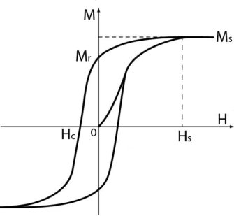
Fig.1: Magnetic Hysterisis
A magnetic hysteresis, otherwise known as a hysteresis loop, is a representation of the magnetizing force (H) versus the magnetic flux density (B) of a ferromagnetic material. The curvature of the hysteresis is characteristic of the type of material being observed and can vary in size and shape (i.e. narrow or wide). The loop can be generated by using a Hall Effect sensor to measure the amount of magnetic field at various points - when in the presence of a magnetic field, when it is removed from the magnetic field, and when a force is applied to bring the magnetic flux back to zero. These loops are important in the memory capacity of devices for audio recording or magnetic storage of data on computer disks.
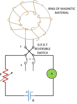
For understanding the phenomenon of the magnetic hysteresis, consider a ring of magnetic material wound uniformly with solenoid. The solenoid is connected to a DC source through a Double pole double throw (D.P.D.T) reversible switch as shown in the figure below:

Fig: 2 Experiment diagram
Initially, the switch is in position 1. By decreasing the value of R the value of the current in the solenoid increases gradually resulting in a gradual increase in field intensity H, the flux density also increases till it reaches the saturation point a and the curve obtained is ‘OMs‘. Saturation occurs when on increasing the current, dipole moment or the molecules of the magnet material align itself in one direction.
Now by decreasing the current in the solenoid to zero the magnetizing force is gradually reduced to zero. But the value of flux density will not be zero as it still has the value ‘OMr‘ when H=0, so the curve obtained is ‘MsMr‘ as shown in the figure below. This value ‘OMr ‘ of flux density is because of the residual magnetism.
Residual Magnetism
The value of the flux density ob retained by the magnetic material is called residual magnetism, and the power of retaining it is known as Retentivity of the material.
Coercive Force
The value of the magnetizing force oc required to wipe out the residual magnetism ob is called Coercive force
Application:
- Magnetic material having a wider hysteresis loop is used in devices like magnetic tape, hard disk, credit cards, audio recordings as its memory is not easily erased.
- Magnetic materials having a narrow hysteresis loop are used as electromagnets, solenoids, transformers and relays which require minimum energy dissipation.
- To understand temperature effects, we need to look at the atomic structure of the elements that make up the magnet. Temperature affects magnetism by either strengthening or weakening a magnet’s attractive force. A magnet subjected to heat experiences a reduction in its magnetic field as the particles within the magnet are moving at an increasingly faster and more sporadic rate. This jumbling confuses and misaligns the magnetic domains, causing the magnetism to decrease. Conversely, when the same magnet is exposed to low temperatures, its magnetic property is enhanced and the strength increases.
- In addition to the strength of the magnet, the ease at which it can be demagnetized also varies with temperature. Like magnet strength, demagnetization resistance generally decreases with increasing temperature. The one exception is ceramic (ferrite) magnets, which are easier to demagnetize at low temperature and harder to demagnetize at high temperature.
- Different magnet materials react differently with temperature. Alnico magnets have the best strength stability followed by SmCo, NdFeB, and then ceramic. NdFeB magnets having the highest resistance to demagnetization (coercivity), but the largest change with temperature. Alnico magnets have the lowest resistance to demagnetization, but the smallest change with temperature. Alnico have the highest service temperature followed by SmCo, ceramic and then NdFeB.
- Not everyone realizes that the shape of a magnet affects its maximum usable temperature. This is especially important for NdFeB magnets because they have the greatest change in demagnetization resistance with temperature. As the length of the magnetized axis increases, its resistance to demagnetization also increases.
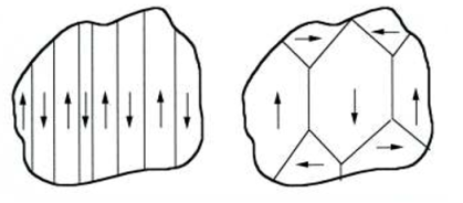
The reason magnets stick to ferro metals is because of a special characteristic about the atoms inside these metals. In most other materials that are not magnetic, the magnetic moments of the atoms inside are all oriented in random directions that cancel each other out. In ferromagnetic materials, the atoms form structures called domains. A domain is a region inside of a material where groups of magnetic moments naturally align in the same direction.


Fig: 3 Domain Structure
Once we have induced a magnet, we can observe an interesting effect when the external magnetic field is removed. Depending on the material, the domains will stay lined up together in the same direction even after the external field is gone. The domains do not instantly return to normal. This tendency to stay aligned is called hysteresis. Hysteresis is what allows us to make permanent magnets. To make permanent magnets, we take our material, create whatever shape we want, and then place the material inside of a very strong magnetic field. The domains inside the material align with the magnetic field, and when we remove the field, the domains stay aligned, and we now have a new magnet. While these are magnets are not truly “permanent”, some magnets’ domains will not return to their original state for much longer than a single lifetime.
Reference Books
i) Electrical Engineering Materials, Dr. G.P. CHHALOTRA & Dr. B.K.BHAT, Khanna Technical Publications