Unit 1
Introduction to Vector Algebra
Vector algebra is essential in developing the concepts of electromagnetic field theory. The widespread acceptance of vectors in electromagnetic field theory is because they provide compact mathematical representations of complicated phenomena and allow for easy visualization and manipulation.
Scalar and vector quantities
Most of the quantities encountered in electromagnetic fields can easily be divided into two classes, scalars, and vectors.
Scalar
A physical quantity that can be completely described by its magnitude is called a scalar. Some examples of scalar quantities are mass, time, temperature, work, and electric charge.
Vector
A physical quantity having a magnitude as well as a direction is called a vector. Force, velocity, torque, electric field, and acceleration are vector quantities.
1.1.1 Coordinate system.
The various coordinate systems are:
(i) Cartesian or rectangular co-ordinate system
(ii) Cylindrical co-ordinate system
(iii) Spherical co-ordinate system
Representing a point in Rectangular Co-ordinate system
A point in rectangular co-ordinate system is located by three co-ordinates namely x,y and z co-ordinates. The point can be reached by moving from origin the distance of x in x-direction , distance of y in y-direction and finally distance of z in z direction.
Consider a point P having co-ordinates x1,y1 and z1 which can be positive or negative.
The point Q(3,-1,2) can be shown as
 Figure 1. Rectangular co-ordinate system |
Base vector :
The base vector are the unit vectors that are oriented along the directions of the co-ordinate axes of the given co-ordinate system. Thus for cartesian co-ordinate system the three base vectors are unit vectors oriented in x,y and z axis of the system. Therefore
  ,
, and
and  are the base vectors of the cartesian co-ordinate system.
Any point of the x-axis having (x1,0,0) can be represented by a vector joining origin to this point to this point and denoted as x1 .
.
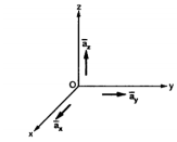
Figure 2. Base vector
Position and Distance vectors :
Consider a point P(x1,y1,z1) in cartesian co-ordinate system as shown in figure. Then the position vector of point P from the origin directed from origin to point P. This is called radius vector as shown in figure.
The three components of position vector oriented along the three co-ordinate axes with magnitudes x1,y1and z1. Thus the position vector of point P can be represented as

Figure 3. Position vector
 OP= x1
  + y1
+ y1  + z1
+ z1 
The magnitude of this vector in terms of three mutually perpendicular components is given by
| OP|=
OP|= 2 + (y1) 2+ (z1) 2
Thus, if point P has co-ordinates (1,2,3) then its position vector is
 OP=1
OP=1  + 2
+ 2  + 3
+ 3 
And
 OP =
OP = (1) 2 + (2) 2 + (3) 2 =
  = 3.7416
Consider two points in a cartesian coordinate system P and Q with the co-ordinates (x1,y1,z1) and (x2,y2,z2) respectively. The individual position vectors of the points are
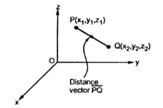
Figure 4. Cartesian coordinate system
 = x1
= x1  + y1
+ y1  + z1
+ z1 
 = x2
= x2  + y2
+ y2  + z2
+ z2 
Then the displacement from P to Q is represented by the distance vector  and is given by
 =
=  -
-  = [x2 -x1]
  + [ y2 -y1]
  + [z2 -z1]
This is called separation vector.
The magnitude of the vector is given by
| | = √ (x2 -x1) 2 + (y2 -y1) 2 +(z2 – z1) 2
This is called as distance formula.
The unit vector along the direction PQ is given by
 PQ= Unit vector along PQ =
  / |PQ|
Obtain the unit vector in the direction from the origin towards the point P(3,-3,-2)
Solution:
The origin O(0,0,0) while P(3,-3,-2) hence the distance vector  is
is
 = (3-0)
  + (-3-0)
  +(-2-0)
  = 3
= 3  -3
-3  -2
-2 
 =
=  (3) 2 + (-3) 2 + (-2) 2 = 4.6904
Hence the unit vector along the direction OP is
 OP=
OP=  / |
/ | | = 3
| = 3  -3
-3  -2
-2  / 4.6904 =
= 0.6396 -0.63963
  -0.4264
Differential Elements in Cartesian Co-ordinate System
Consider a point P(x,y,z) in the rectangular co-ordinate system . If we increase each co-ordinate by a differential amount a new point P’ will be obtained having co-ordinates (x+dx, y +dy ,z+dz)
Dx = differential length in x-direction
Dy = differential length in y-direction
Dz = differential length in z-direction
Hence differential vector length called elementary vector length
 = dx
= dx  -dy
-dy -dz
-dz .
.
P is the intersection of the three planes and P’ is the intersection of the new three planes which are displaced from original three planes. These six planes together define a differential volume which is a rectangular parallelepiped as shown in the figure.
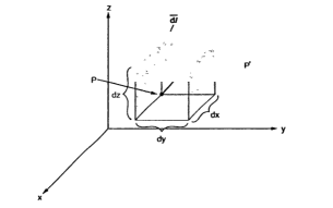
Figure 5. Cartesian coordinate system
 = dx
= dx  -dy
-dy -dz
-dz .
.
Hence the differential volume of the rectangular parallel piped is given by
Dv = dx dydz
 is vector and dv is scalar.
The differential surface area is given by
 =
=  n
n
Ds = Different surfaces area of the element .

Figure 6. Differential vector system
d = Differential vector surface area normal to x direction dy dz
d = = Differential vector surface area normal to y direction dx dz
d = = Differential vector surface area normal to y direction dx dy
Given the three points in cartesian co-ordinate system as A(3,-2,1) B (-3,-3,5) , C (2,6,-4)
Find
i) The vector from A to C
Ii) The unit vector from B to A
Iii) The distance from B to C
Iv) The vector from A to the mid-point of the straight line joining B to C.
The position vectors for the given points are :
 = 3
= 3 - 2
- 2 +
+ .
.
 = -3
= -3 - 3
- 3 +5
+5  .
.
 = 2
= 2 +6
+6 -4
-4 .
.
i) The vector from A to C is
 =
=  -
-  = [ 2-3]
  +[6–(-2)]
 +[-4-1]
  .
.
= -  + 8
+ 8 -5
-5  .
.
Ii) For unit vector from B to A obtain the distance vector  first
first
 =
=  -
- 
= [ 3 – (-3)] + [ (-2) –(-3) ]
  + [ -4-1]
= 6  +
+  -4
-4  .
.
| | =
| =  (6) 2 + (1) 2 + (-4)2 = 7.2801.
 BA =
BA =  / |
/ | | = 6
| = 6  +
+  -4
-4  ./ 7.2801
Iii) For distance between B and C
 =
=  -
-  = [ 2 –(-3 ]
  + [6-(-3)]
  +[-4) –(-5)]
  = 5
= 5  + 9
+ 9  – 9
– 9 
Distance BC =  2 + (9) 2 + (-9) 2 = 13.6747
Iv) Let B(x1,y1,z1 ) and C(x2,y2,z2) then the co-ordinates of the mid-point BC are (x1+x2/2 , y1+y2/2 , z1+z2/2)
Cylindrical co-ordinate system
The circular cylindrical co-ordinate system is a three dimensional version of polar co-ordinate system. The surfaces used to define the cylindrical co-ordinate system are :
- Plane of constant z which is parallel to xy plane.
- A cylinder of radius r with z-axis of the cylinder
- A half plane perpendicular to xy plane at angle Ø with respect to xzplane . The angle Ø is called the azimuth angle.
The ranges of the variable are :
0 ≤ r ≤ ∞------------------(1)
0 ≤Ø≤ 2π------------------------------(2)
-∞≤z≤∞--------------------------------------------------(3)
The point P in cylindrical co-ordinate system has three co-ordinates r, Ø and z whose values lie in the ranges given by equations 1,2,3.
The point P(r,Ø1,z1) can be shown in figure (b)
 Figure 7. Cylindrical coordinate system |
The point P can be defined as the intersection of three surfaces in cylindrical co-ordinate system. These three surfaces are,
r = Constant which is circular cylinder with z axis as its axis
Ø= Constant plane which is a vertical plane perpendicular to xy plane making angle Ø with respect to xz plane.
z= Constant plane is a plane parallel to xy plane.
These surfaces are shown in figure.
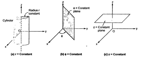 Figure 8. Surfaces of cylindrical coordinate system |
The intersction of any two surfaces out of the above three surfaces is either a line or a circle and intersection of three surfaces define a point.
The intersection of z=constant and r=constant is a circle. The intersection of ɸ=constant and r=constant is a line. The point P which is intersection of all three surfaces is shown in the figure.
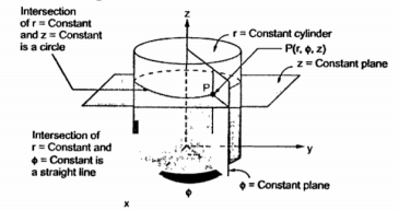 Figure 9. Intersection |
Base vectors:

Figure 10. Base vector
These are mutually perpendicular to each other. The  lies in a plane parallel to xy plane and perpendicular to the surface of the cylinder at a given point coming radially outwards. The vector
  lies also in a plane parallel to xy plane but it is tangent to the cylinder and pointing in the direction of increasing
  at the given point.
The unit vector  is parallel to z-axis and directed towards increasing z . Hence, vector of point P can be represented as
 = P r
= P r  + P ɸ
+ P ɸ + P z
+ P z 
Differential Elements in Cylindrical co-ordinate system
Consider o point P(r,ɸ,z) in a cylindrical co-ordinate system. Let each co-ordinate be increased by differential amount. The differential increments in r,ɸ,z are dr,dɸ and dz respectively.
There are two cylinders of radius r and r+dr. There are two radial planes at the angles ɸ and ɸ+dɸ. And there are two horizontal planes at the heights z+dz. All these surfaces enclose a small volume as shown in figure.
The different lengths in r and z are dz and dr respectively. In ɸ direction dɸ is the change in angle ɸ and is not the differential length. Due to this change dɸ there exists a differential arc length in ɸ direction. This differential length due to dɸ in ɸ direction is r dɸ as shown in figure.
Thus the differential lengths are :
Dr = Differential length in r direction.
r dɸ = Differential length in ɸ direction
Dz = Differential length in z direction
Hence the differential vector length in cylindrical co-ordinate system is given by
 = dr
= dr  + r dɸ
 + dz
+ dz 
The magnitude of the differential length vector is given y
| (dr) 2 +( r d ɸ) 2 + (dz) 2
Hence the differential volume of the differential element is given by
Dv = r drdɸdz
- Spherical co-ordinate system:
The surfaces which are used to define the spherical co-ordinate system on the three cartesian axes are:
- Sphere of radius r, origin as the centre of the sphere.
- A right circular cone with its apex at the origin and its axis as z-axis. It half angle is Ѳ varies from 0 to 180.
- A half plane perpendicular to xy plane containing z axis making an angle Ø with xz plane.
Thus the three co-ordinates of a point P in the spherical co-ordinate system are (r,Ѳ,Ø). These surfaces are shown in figure
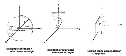 Figure 11. Spherical coordinate system. 
|
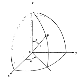 Figure 12. Points in the spherical coordinate system |
The point P(r,Ѳ,Ø) can be represented in the spherical co-ordinate system as shown in figure. The angles Ѳ and Ø are measured in radians. The point P can be defined as the intersection of three surfaces in spherical co-ordinate system. These three surfaces are:
r = Constant which is a sphere with cenre as origin
Ɵ = Constant which is right circular cone with apex as origin and axis a z axis
ɸ= Constant is a plane perpendicular to xy plane.
Base Vector:
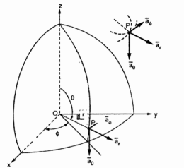
Figure 13. Base vector
There are three unit vectors in r, Ɵ and ɸ directions denoted as  ,
,  and
and  . These unit vectors are mutually perpendicular to each other as shown in figure. The unit vector
  is directed from the centre of the sphere that is the origin to the given point P. It is radially outward normal to the sphere. It lies in the cone Ɵ = constant and plane ɸ= constant .
The unit vector  is tangent to the sphere and oriented in the direction of increasing Ɵ. It is normal to the conical surface.
The third unit vector  is tangent to the sphere and also tangent to the conical surface . It is oriented in the direction of increasing ɸ. It is same as defined in the cylindrical co-ordinate system.
Hence, vector P is
 = Pr
= Pr  + P
+ P + Pɸ
+ Pɸ
Differential elements in Spherical co-ordinate system.
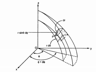
Figure 14. Spherical coordinate system
Consider a point P(r,Ɵ,ɸ) in spherical co-ordinate system. Let each co-ordinate be increased by the differential amount. The differential increments in r,Ɵ,ɸ are dr,dƟ and dɸ.
Now there are two spheres of radius r and r+dr . There are two cones with half angles Ɵ and Ɵ+dƟ. There are two planes at the angles ɸ+dɸ measured from xz plane. All these surfaces enclose a small volume as shown in figure.
Dr= Differential length in r direction
r d Ɵ = Differential length in Ɵ direction
r sin Ɵdɸ = Differential length in ɸ direction.
Hence the differential vector length in spherical coordinate system is
 = dr
= dr  + r d
+ r d + r sin
  dɸ
dɸ
The magnitude of the differential length vector is
| | = √ (dr) 2 + (r d
 2 + (r sin
  dɸ) 2
dɸ) 2
Hence differential volume is given by
Dv = r 2 sin  dr d
dr d d
d 
Key Take Aways:
A Cartesian coordinate system is a coordinate system that specifies each point uniquely in a plane by a set of numerical coordinates, which are the signed distances to the point from two fixed perpendicular oriented lines, measured in the same unit of length.
1.1.2 Transformations
Rectangular to cylindrical
The transformation of rectangular to cylindrical coordinates requires that we find the components of the rectangular coordinate vectorA in the direction of the cylindrical coordinate unit vectors using dot product.
Transformation:
(Ax,Ay,Az) ----- (Ar,Aɸ,Az)
The required dot products are
Ar = A.  = Ax .
 + Ay
+ Ay  + A.
+ A.  = Ax .
 + Ay
+ Ay 
Aɸ = A.  = Ax .
 + Ay
+ Ay  + A.
+ A.  = Ax .
 + Ay
+ Ay 
Az = A.  = Ax .
 + Ay
+ Ay  + Az.
+ Az.  = Az
= Az
Where  .
.  =0
=0  .
.  =0
=0  .
.  =0
=0  .
.  =0
=0  .
.  =1
=1
The four remaining unit vector dot products are determined according to the geometry relationships between the two coordinate systems.
 = cos ɸ
 + sin ɸ
ɸ = - sin ɸ  + cos ɸ
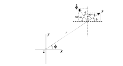
Figure. 15. Rectangular co-ordinate
 .
.  =
=  . ( cos ɸ
 + sin ɸ
 ) = cos ɸ
 .
.  =
=  . ( cos ɸ
 + sin ɸ
 ) = sinɸ
 . ɸ =
. ɸ =  . ( -sin ɸ
 + cos ɸ
 ) = -sin ɸ
 . ɸ =
. ɸ =  . ( -sin ɸ
 + cos ɸ
 ) = cos ɸ
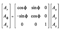
The resulting cylindrical coordinate vector is A = Ar .  + A ɸɸ + Az
= (Ax cos ɸ + Ay sin ɸ)  + (Ay cos ɸ - Ax sin ɸ) ɸ + Az
The rectangular to cylindrical transformation is
Rectangular to spherical
Transformation:
(Ax,Ay,Az) ----- (AR,A ,Aɸ)
,Aɸ)
The required dot products from rectangular to spherical are
Ar = A.  = Ax .
 + Ay
+ Ay  + Az
+ Az 
A = A.
= A.  = Ax .
 + Ay
+ Ay  + Az
+ Az 
A = A.ɸ =Ax .
  ɸ + Ay
  + Az.
+ Az.  ɸ
ɸ
The geometry relationships between the rectangular and spherical unit vectors are shown below:
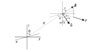
Figure. 16 Rectangular to spherical
 = sin
= sin  .
.  + cos .
= sin  [ cos ɸ
 + sin ɸ
 ] + cos
 = cos
= cos  .
.  - cos( 90 –
  )
) 
= cos  .cos ɸ
 + cos
+ cos  . Sin ɸ.
  – sin
– sin 
 = - sin
  .
.  + cos ɸ .
The dot products are then
 .
.  = sin
= sin  . Cos
. Cos 
 .
.  = sin
= sin  . Sin
. Sin 
 .
.  = cos
= cos 
 .
.  = cos
= cos  . Cos
. Cos 
 .
.  = cos
= cos  . Sin ɸ
 .
.  = - sin
 .
.  = - sin ɸ
 .
.  = cosɸ
 .
.  = 0
= 0
The rectangular to spherical transformation may be written as

Spherical to Rectangular
(AR,A ,Aɸ) -------- (Ax,Ay,Az)
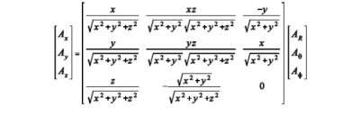
The spherical to rectangular coordinate transformation is the inverse of the rectangular to spherical coordinate transformation so that

The spherical coordinate variables in terms of the rectangular coordinate variables are
Sin  = r/R = √ x2 + y2 / √ x2 + y2 + z2 cos
  = z/R = z / √x2 + y2 + z2
The complete spherical to rectangular transformation is
Cylindrical to rectangular:
The transformation from cylindrical to rectangular can be determined as the inverse of the rectangular to cylindrical transformation.
Transformation:
(Ar,Aɸ,Az) = (Ax,Ay,Az)
The transformation from cylindrical to rectangular coordinates can be determined as the inverse of rectangular to cylindrical transformation.
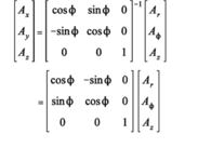
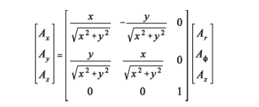
The cylindrical coordinates variables in the transformation matrix must be expressed in the terms of rectangular coordinates
Cosɸ = x/r = x / √x2 + y2
Sin ɸ = y/r = y/ √ x2 + y2
The resulting transformation is
The cylindrical to rectangular transformation can be written as
A = Ax + Ay
+ Ay  + Az
+ Az 
= (Ar cos ɸ - Aɸ sin ɸ)  + (Ar sin ɸ + Aɸ cos ɸ)
  + Az
+ Az
= Ar . x/ √ x 2 + y 2 – A ɸ . y / √ x 2 + y2 )  + Ar( y/ √ x 2 + y 2 + Aɸ . x / √ x 2 + y 2 )
  + Az
+ Az 
Key Take Aways :
Vector can be converted from one co-ordinate system to another.
1.2.1Differentiation
Consider a scalar valued function of scalar for example time -dependent density of a material  =
= 
Consider vector valued function of scalar for example time -dependent displacement of a particle u = u(t). In this case the derivative in the usual way
Du/dt = lim ∆t->0 u(t+∆t) – u(t) / ∆t
Which turns out to be simply the derivative co-efficient
Du/dt = du1/dt e1 + du2/dt e2 + du3/dt = dui/dt ei
1.2.2 Partial differentiation:
Partial derivatives can also be defined . For example if u is a function of the coordinates u(x1,x2,x3) then
∂u/ ∂x1 = lim ∆x1->0u(x1+ ∆x1 ,x2,x3) – u( x1,x2,x3) / ∆x1
1.2.3 Integration
The line integrals of vector fields as a line integral with respect to arc length as follows,
 . d
. d  =
=  .
.  ds
ds
Where →T(t) is the unit tangent vector and is given by,
 (t) =
(t) =  ’(t) ||
 ’(t)||
To compute line integrals with respect to arc length we can see that this second form is equivalent to the first form given above.
 . d
. d  =
=  .
.  ds
ds
=  (
(  ‘(t) / ||
  ‘(t) || ||
 ‘(t) || dt
=  (
(  ‘(t) ) .
  ‘(t) dt
Key Take Aways:
Vector calculus is concerned with differentiation and integration of vector fields, primarily in 3-dimensional Euclidean space
1.3.1 Coulombs law
It states that force between two point charges Q1 and Q2
- Acts along the line joining the two point charges.
- Is directly proportional to the product of Q1Q2 of the two charges
- Is inversely proportional to the square of the distance between them.

Figure 17. Two point charge
Consider two point charges Q1 and Q2 as shown in the figure seperated by distance R. The charge Q1 exerts a force on Q2 while Q2 also exerts a force on Q1. The force acts along the line joining Q1 and Q2. The force exerted between them is repulsive if the chrages are of same polarity while it is attractive if the charges are of different polarity.
Mathematically the force F between the charges can be expressed as ,
F α Q1Q2/ R 2
Q1Q2------ Product of two charges
R ------- Distance between the two charges
The law also states that the force depends on the medium in which the point charges are located. The effect of medium is introduced in the equation of force as a constant of proportionality denoted as k.
F = k . Q1 Q2/ R2
The constant of proportionality takes into account the effect of medium.
Therefore,
k = 1/ 4 π 
 = Permittivity of medium in which charges are located . The units of
  are farads/metre(F/m)
In general  is expressed as ,
 =
= 
 Permittivity of free space or vacuum
 = Relative permittivity or dielectric constant of the medium with respect to free space.
 Absolute permittivity
For free space or vacuum the relative permittivity  hence
hence
 =
= 
F = 1/ 4 π  . Q1Q2/ R2
The value of permittivity of free space  is
is
 1/ 36 π x 10 -9 = 8.854 x 10 -12 F/m
k = 1/ 4π  = 1/ 4π x 8.854 x 10 -12 = 8.98 x 10 9 = 9 x 10 9 m/F
Hence the Coulombs law can be expressed as ,
F = Q1 Q2 / 4π  R 2
R 2
This the force between the two point charges located in free space or vacuum.
Problem:
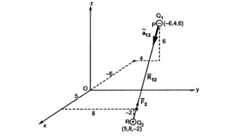
A charge Q1=-20µC is located at P(-6,4,6) and a charge Q2=50µC is located at R(5,8,-2) in a free space . Find the force exerted on Q2 by Q1 in vector form. The distances given are in meters.
From the co-ordinates of P and R the respective position vectors are :
 = -6
= -6  + 4
+ 4  + 6
+ 6 
And
 = 5
= 5  + 8
+ 8  -2
-2 
The force on Q2 is given by
 = Q1 Q2 / 4 π
  R212 .
 =
=  =
=  -
-  = [ 5 –(-6)]
  + (8-4)
  + [-2-(-6)
  ]
]
= 11  + 4
+ 4  - 8
- 8 
|R12| =  (11) 2 + (4) 2 +(-8) 2 = 14.1774
 =
=  / |
/ | | = 11
  + 4
+ 4  -8
-8  / 14.1774
 = -20 x 10 -6 x 50 x 10 -6 / 4 π x 8.854 x 10 -12 x (14.1774) 2 [
= -0.0447 [ 0.7758  + 0.2821
  - 0.5642
  ]
]
= -0.0346  - 0.01261
  + 0.02522
  N
N
This is the required force exerted on Q2 by Q1
The magnitude of the force is
| =
=  (0.0346) 2 + (0.01261 ) 2 + (-0.02522) 2 = 44.634mN
1.3.2 Gauss law and its applications
Definition:
The electric flux passing through any closed surface is equal to the total charge enclosed by that surface.
The total charge enclosed by the irregular closed surface is Q coulombs. Hence the total flux has to pass through the closed surface is Q. Consider a small differential surface dS at point P. As the surface is irregular the direction of D as well as its magnitude is going from point to point on the surface. The surface dS under consideration can be represented in vector form.
d  = d S
= d S 
Where  = Normal to the surface d at point P
The flux density at point P is D and its direction is such that it makes an angle Ѳ with the normal direction at point P.
The flux d passing through the surface dS is the product of the component normal to dS and d
 .
.
Mathematically thus can be represented as,
d  = Dn dS
Dn = component of  in the direction of normal to the surface dS
From the figure we can write
Dn = | | cos
| cos 
d  = |
= | | cos
| cos  dS
dS
From the definition of the dot product
 .
.  = |A| |B| cos ƟAB
| | cos
| cos  dS =
dS =  d
d 
This is the flux passing through incremental surface area dS. Hence the total flux passing through the entire closed surface is to be obtained by finding the surface integration of the equation
 =
=  =
= 
 sign indicates the integration over the closed surface called closed surface integral.
Such a closed surface over which the integration in eq(6) is carried out is called Gaussian surface.
Total charge enclosed by the surface is given by
 =
=  = Q = Charge enclosed.
Applications:
Infinite line charge:
Consider an infinite line charge of density  C/m lying along the z-axis from -
  to
to  as shown in figure.
Consider the Gaussian surface as the right circular cylinder with z-axis as its axis and radius r as shown in figure. The length of the cylinder is L.
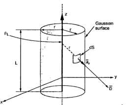
Figure 18. Infinite Line charge
The flux density at any point on the surface is directed radially towards that is in the  direction according to cylindrical co-ordinate system.
Consider differential surface area dS as shown which is at a radial distance r from the line charge. The direction is normal to dS is 
As the line charge is along z-axis there cannot be any component D in z direction .So D has only radial component.
Now Q =  . d
. d 
The integration is to be evaluated for side surface , top surface and bottom surface
Q =  . d
. d  +
+  . d
. d  +
+  . d
. d 
 = Dr
= Dr  as has only radial component
d  = r dɸdz
 normal to
  direction
 . d
. d  = D rrdɸdz (
 .
.  = D rrdɸdz
D r is constant over the side surface.
As  has only radial component and no component along
 and -
and -  hence integrations over top and bottom surfaces is zero.
 . d
. d  =
=  . d
. d 
Q =  . d
. d  =
=  r dɸdz
=  r dɸdz = r Dr [ z] 0L [ ɸ] 02π
Q = 2  r Dr L
Dr = Q / 2  r L
r L
 = Dr
= Dr  = Q / 2
  r L .
r L . 
Q/L =  / 2
/ 2  r .
r .
 =
=  /
/  = =
= =  / 2
/ 2  r .
r . V/m
V/m
Key Take Aways:
Gauss Law states that the total electric flux out of a closed surface is equal to the charge enclosed divided by the permittivity.
1.3.3 Potential functions
The name potential is given by Green who showed that the function could be used in electrostatics if the masses are replaced by charges and in magnetostatics if the masses are replaced by magnetic poles or dipoles. The energy here is the energy of the position and therefore it is called potential energy.
The electrostatic potential is
ɸe = 1/ 4π = = 1/ 4π
 / r . Dv ---------------(1)
Where Qi is the charge of the particle and  is the permittivity , r is the distance between the particle and the point at which the potential is calculated
  is the volume density of the charge and v is the volume occupied by the charges. The electric field is given by
 = -grad ɸe-----------------------------------------------(2)
The electric flux density is given by the constitutive equation
 =
=  ------------------------------------------------------(3)
1.3.4 Equipotential surface
An equipotential surface is a three-dimensional surface in which the electric potential V is the same at every point.
Using the example of a single positive charge q, the expression for V is:
V=14πϵ0qrV=14πϵ0qr
If a test charge q0 is moved from point to point on an equipotential surface, the electric potential energy q0V will remain constant. In equation form, this means that the work done is 0:
W=–ΔU=–q0ΔV=0
It follows that →E must be perpendicular to the equipotential surface at every point.
We know that
DV=∂V/∂x.dx+∂V/∂ydy+∂V/∂z. Dz
 . V .
. V .
= -  .
. 
Since dV=0,  .
.  is 0 -> perpendicular.
At each point the direction of  is the direction in which V decreases most rapidly.
DV =  . V .
. V .
= -  .
. 
= -E dl cos ɸ
Where ɸ is the angle between electric filed and the displacement vector.
Key Take Aways:
Equipotential surface is an imaginary surface in an electric field of a given charge distribution in which all the points on the surface are at the same electric potential.
Poisson’s Equation:
From the Gauss’s law in the point form Poisson’s equation can be derived. Consider the Gauss’s law in the point form as
 .
.  =
= 
 = flux density
 Volume charge density.
For a homogeneous isotropic and linear medium, flux density and the electric field are directly proportional . Thus,
 =
=  .
. 
 .
.  .
.  =
= 
From the gradient relationship
E = -  . V
. V
 .
.  (-
(-  . V) =
 (
(  .
.  V) =
V) = 
 .
.  V) =-
V) =-  /
/ 
Now  .
.  operation is called ‘del squared’ operation denoted as
  2.
2.
 2. V = -
  /
/ 
This equation is called as Poisson’s Equation
Laplace equation
If in a certain region volume charge density is zero (  which is true for dielectric medium then the Poisson’s equation takes the form,
 2. V =0.
This equation is called Laplace’s equation.
1.4.1Application of Laplace and Poisson’s Equations.
Using Laplace or Poisson’s equation we obtain:
- Potential at any point in between two surfaces when potential at two surface are given.
- We can also obtain capacitance between these two surfaces.
Solution to simple cases
The procedure to solve a problem involving Laplace’s equation is :
Step 1: Solve the Laplace equation using the method of integration. Assume constants of integration.
Step2. Determine the constants by applying the boundary conditions given or known for the region. The solution obtained in step1 with constants obtained using boundary conditions is an unique solution.
Step 3: Then  can be obtained for the potential field V obtained using gradient operation -
  V.
V.
Step 4. For homogeneous medium  can be obtained as
  .
.
Step 5: At the surface  = DN hence
 is known. The normal component DN to the surface is known. Hence the charged induced on the conductor surface can be obtained as
Q = -  dS
dS
Step 6: Once the charged induced Q is known and potential V is known then the capacitance C of the system can be obtained.
If  0 then the same procedure can be obtained to solve Poisson’s equation.
Key Take Away:
This is useful approach for calculation of electric potentials.
Consider two conducting materials M1 and M2 which are placed in a dielectric medium having permittivity . The material M1 carries a positive charge Q while the material M2 carries a negative charge equal in magnitude as Q. There are no other charges present and the total charge of the system is zero.
In conductors, charges cannot reside within the conductor and it resides only on the surface. Thus, for M1 and M2 charges +Q and -Q reside on the surfaces M1 and M2 respectively. This is shown in figure.

Figure 19. Capacitance
Such a system which has two conducting surfaces carrying equal and opposite charges separated by a dielectric is called capacitive system giving rise to capacitance.
The electric field is normal to the conductor surface and the electric flux is directed from M1 and M2 in such a system. There exists a potential difference between the two surfaces of M1 and M2. Let this potential be V12. The ratio of magnitudes of the total charge on any one of the two conductors and the potential difference between the conductors is called capacitance of the two conductor system denoted as C.
C = Q/ V12
In general C =Q/V
Where Q = charge in coulombs
V = Potential difference in volts.
The capacitance is measured in farads.
1.5.1 Electrostatic Energy
Consider a structure consisting of two perfect conductors, both fixed in position and separated by an ideal dielectric. When a potential difference is applied between the two conducting regions, a positive charge Q+ will appear on the surface of the conductor at the higher potential, and a negative charge Q−will appear on the surface of the conductor at the lower potential. Assume that the conductors are not free to move, potential energy is stored in the electric field associated with the surface charges
Since capacitance C relates the charge Q+ to the potential difference V from the definition of capacitance
V=Q+C-----------------------------------------(1)
The electric potential is defined as the work done by moving a charged particle, per unit of charge; Hence
V=Weq-------------------------------(2)
Where q is the charge borne by the particle and We (units of J) is the work done by moving this particle across the potential difference V.
Since we are dealing with charge distributions as opposed to charged particles, let us is useful to express this in terms of the contribution ΔWe to We by a small charge Δq. Letting Δq approach to zero we get
DWe=Vdq-------------------------------------(3)
For transition to happen the system from having zero charge (q=0) to the fully-charge but static condition (q=Q+). This requires moving the differential amount of charge dq across the potential difference between conductors, beginning with q=0 and continuing until q=Q+. Therefore, the total amount of work done in this process is:
We = 
=  dq
dq
=  dq
dq
= ½ Q 2+/C -----------------------------------------------------------------------------(4)
This cab be expressed entirely in terms of electric potential by noting that C= Q+/V so
We = ½ CV 2 ------------------------------------------------------------------------------(5)
1.5.2 Conductor properties and boundary equations between dielectric and dielectric- conductor interface
Let us consider the boundary between two perfect dielectrics. One dielectric has permittivity  while the other has permittivity
 . The interface is as shown in figure.
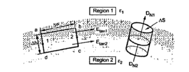
Figure 20. Boundary conditions
The  and
and  are obtained again by resolving each into two components tangential to the boundary and normal to the surface.
Consider a closed path abcda rectangular in shape having elementary height ∆h and elementary width ∆h as shown in figure. It is placed in such a way that ∆h/2 is in dielectric 1 while the remaining dielectric 2. Let us evaluate the integral 
Along this path tracing it in clockwise direction as a-b-c-d-a.
 . d
. d  = 0
= 0
 . d
. d  +
+  . d
. d  +
+  . d
. d  +
+  . d
. d  =0
=0
Now  =
=  +
+  1N
1N
 =
=  +
+  2N
2N
Both  and
and  in the respective dielectrics have both the components , normal and tangential .
Let |  | = E tan1 |
  | = E tan 2
|  | = E 1N |
  | = E 2N
Now for rectangle to be reduced at the surface to analyse boundary conditions ∆h->0 .As ∆h->0 the equation reduces to
 and
and  become zero as these are line integrals along ∆h and ∆h ->0.
Hence equation reduces to
 . d
. d  +
+  . d
. d  =0
=0
Now a-b is in dielectric 1 hence the corresponding component of  E tan1 as a-b direction is tangential to the surface.
 . d
. d  = E tan1
  = E tan1 ∆w
Now a-b is in dielectric 1 hence the corresponding component of  E tan1 as a-b direction is tangential to the surface.
 . d
. d  = E tan2 ∆w
E tan1 ∆w - E tan2 ∆w =0
E tan1 = E tan2 ∆w
Thus the tangential components of field intensity at the boundary in both the dielectric remains same that is electric field intensity is continuous across the boundary.

Hence if D tan1 and D tan2 are magnitudes of the tangential components of  in dielectric 1 and 2 respectively then
D tan1 = 
Hence if D tan1 and D tan2 are magnitudes of the tangential components of  in dielectric 1 and 2 respectively then
D tan1 =  E tan1 and D tan2 =
  E tan2
D tan1/  = D tan2 /
Dtan1/ Dtan2 =  / /
/ /  = /
= /  / /
/ / 
Thus tangential components of  undergoes some change across the interface hence tangential
  undergoes some change across the interface hence tangential
  is said to be discontinuous across the boundary.
Key Take Aways:
The dielectric constant of a material, also called the permittivity of a material, represents the ability of a material to concentrate electrostatic lines of flux.
Assume that the Laplace’s equation has two solutions say V1 and V2 both are the function of the coordinate system. These solutions must satisfy Laplace equation hence we write,
 2 V1 =0 and
  2 2 =0 -----------------------------------------(1)
Both the solutions must satisfy the boundary conditions as well. At the boundary the potentials at different points are the same due to equipotential surface then
V1 = V2
Let the solution between the two solutions be Vd
Vd = V2 – V1 ---------------------------------------------------------------------(3)
Using Laplace’s equation for the difference Vd
 2Vd =
2Vd =  2 (V2-V1) =0 -----------------------------------------------------------(4)
 2 V2 =
  2 V1 =0 -------------------------------------------------------------------(5)
On the boundary Vd =0 from eq(2) and (3)
Now the divergence theorem states that
 .
.  dv =
dv =  . d
. d ---------------------------------------------------------(6)
Let  = Vd
= Vd Vd from vector algebra
 . (
. ( ) =
) =  (
( .
.  ) +
) +  .(
.( 
Now use this for  (Vd
(Vd Vd) with
  =Vd and
  . Vd =
 (Vd
(Vd  Vd) = Vd (
 .
. . Vd) +
  Vd . (
 Vd) --------------------------------(7)
But  .
. =
=  2
2
 (Vd
(Vd Vd) =
Vd) =  Vd .
Vd . Vd ----------------------------------------------(8)
To use this in equation(6) let A= Vd Vd hence
=  Vd .
Vd . Vd =
Vd =  .
.  =
=  Vd .
Vd . Vd --------------------------------------(9)
But Vd =0 on boundary hence the RHS eq(9) is zero.
Therefore
 Vd .
Vd . vd dv =0 ---------------------------------------------------(10)
This the volume integral to be evaluated on the volume enclosed by the boundary.
It is known that , .
.  = |
= |  | 2
| 2
Therefore
 Vd |2 dv =0 as
  Vd is vector.----------------------------------(11)
Now integration can be zero under two conditions:
(1) The quantity under the integral sign is zero.
(2) The quantity is positive in some regions and negative in some regions by an equal amount and hence zero.
But the squared term cannot be zero in any region hence quantity under integral must be zero.
| Vd 2 | =0
That is  Vd =0
Vd =0
As the gradient of d isV2-V1 is zero means V2-V1 is constant and not changing with any of the coordinates. But considering boundary it can be proved that V2 – V1 =0 .
Therefore V2 =V1
This proves that both the solutions are equal and cannot be different. Thus, Uniqueness Theorem states that:
If the solution of Laplace’s equation satisfies the boundary condition, then that solution is unique by whatever method it is obtained.
The solution of Laplace’s equation gives the filed which is unique satisfying the same boundary condition in each region.
Key Take Aways:
The electromagnetism uniqueness theorem states that providing boundary conditions for Maxwell's equations uniquely fixes a solution for those equations.
References :
- Electromagnetic Field Theory Book by A.V.Bakshi
- Engineering Electromagnetics with CD Book by John Buck and William H. Hayt
- Electromagnetic theory Book by Oliver Heaviside
- Electromagnetic field theory Book by Markus Zahn
- Field and wave electromagnetics Textbook by David K. Cheng