Unit-2
Magnetostatics
Let us consider a conductor carrying direct current I and a steady magnetic field is produced around it. The law helps us to obtain magnetic field intensity  produced at a point P due to differential current element idL. The current carrying conductor is as shown in the figure.
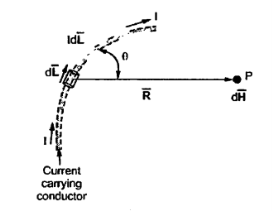
Figure 1. Current carrying conductor
Consider differential length dL and differential current IdL. This is a small part of the current carrying conductor. The point P is at a distance R from differential current element.  is the angle between the differential current element and the line joining point P to the differential current element.
Bio-Savart Law states that the magnetic field intensity  produced at point P due to differential current IdL is,
- Proportional to the product of current I and differential length dL.
- The sine of angle between the element and the line joining point P to the element.
- Inversely proportional to the square of distance R between point P and the element.
Bio-Savart law can be stated as,
d α I dL sin Ɵ / R 2
d =k I dL sin Ɵ / R 2
Where k = constant of proportionality
In SI units, k = 1/ 4 π.
d = I dL sin Ɵ / 4πR 2
In vector form,
Let dL = Magnitude of vector length  and
and
 R = Unit vector in the direction from differential current element to point P.
Then from rule of cross product,
 x
x  R = dL |
 R| sin Ɵ = dL sin Ɵ
| R|=1
R|=1
Replacing we get
d = I d
= I d  x
x  R / 4πR 2 A/m
 R =
R =  / |
/ | =
=  / R
/ R
d = I d
= I d  x
x  / 4πR 3A/m
This is the mathematical form of Bio-Savarts Law.
According to direction of cross product the direction of  is normal to the plane containing two vectors and the normal direction along the progress of right- handed screw turned from
  through smaller angle
  towards the line joining element to point P.
Therefore, direction of  is normal to the plane of paper.
According to right- handed screw rule the direction of  is going into the plane of paper.
The entire conductor is made of differential elements .Therefore, in order to obtain the total magnetic field take the integral
 =
=  d
d  x
x  R / 4πR 2
The closed line integral is required to ensure that all the current elements are considered because current can flow only in the closed path provided by close circuit.
If the current element is considered at point 1 and point P at point 2 as shown in the figure, then
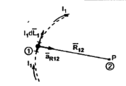
Figure 2. Current element
D  2 = I1 d
  1 x x
1 x x  R 12/ 4πR 2 12
Where
I1 = current flowing through dL1 at point 1.
DL1 = Differential vector length at point 1
 R12 = Unit vector in the direction from element at point 1 to point P at point2.
 R12 =
R12 = / |
/ | | =
| =  / R12
/ R12
 =
=  d
d  x
x  R12/ 4 π R 2 12A/m
This integral form is called Biot-Savart law.
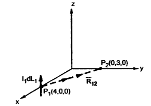
Problem:Find the incremental field strength at P2 due to the current element of 2πa2 Am at P1. The co-ordinates of P1 and P2 are (4,0,0) and (0,3,0) respectively.
Solution:
The two points P1 and P2 along with the I1dL1 current element at I1 are shown in figure.
According to Bio-Savart law
d  = I1 d
  x
x  R12/ 4 π R 2 12
 = (0-4)
  + (3-0) ay + 0. Az
 R12 =
R12 = 12/|
12/|  12|
12|
= -4  x + 3
x + 3  y /
y /  16 + 9
= -4  x + 3
x + 3  y /5
y /5
While I1 dL1 = 2 A m.
A m.
I1  x a R12 = | ax ay az |
| 0 0 2
|-4/5 3/5 0 | = -4/5 x 2 + 4
+ 4 
= -2 [
[  + 4
+ 4  / 4π x (5) 2= - 4 x 10 -3 [
  + 4
+ 4  μA/m
μA/m
= -12 ax – 16 ay nA/m
Key Take Aways:
The Biot-Savart law states how the value of the magnetic field at a specific point in space from one short segment of current-carrying conductor depends on each factor that influences the field.
Gauss’s Law is useful to obtain  in case of complex problems. I magnetostatics complex problems can be solved using Ampere’s Law.
It states that
The line integral of magnetic field intensity  around closed path is exactly equal to direct current enclosed by that path.
The mathematical representation of Ampere’s circuital law is
 .
.  = I -------------------------------------(1)
This law is useful to determine  when current distribution is symmetrical.
Proof:
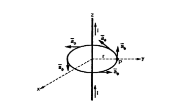
Figure 3. Current carrying conductor
Consider a long straight conductor carrying direct current I placed along z axis as shown in figure. Consider a closed circular path of radius r which encloses the straight conductor carrying direct current I. The point P is at perpendicular distance r from the conductor.
Consider  at point P which is direction
  direction tangential to circular path at point P.
Therefore,
 = r dɸ
While  obtained at point P, from Biot-Savart law due to infinitely long conductor is,
 = 1/ 2 π r .
 ɸ . r dɸ .
 ɸ
ɸ
= 1/ 2  r . dɸ = 1/ 2 π .dɸ
Integrating  .
.  over the entire closed path
 .
.  =
=  dɸ = 1/ 2 π [ɸ] 02π= I. 2 π/ 2 π
This proves that the integral  .
.  along closed path gives the direct current enclosed by that closed path.
- Steps to Apply Amper’s Circuital Law:
Step1: Consider a closed path preferably symmetrical such that it encloses the direct current I once. This is Amperian path.
Step2: Consider differential length depending upon the co-ordinate system used.
Step3: Identify the symmetry and find in which direction  exists according to co-ordinate system used.
Step 4: Find  .
.  . Make sure that
  and
and  are in the same direction.
Step 5: Find the integral of  .
.  around the closed path. And equate it to current I enclosed by the path.
To apply Ampere’s circuital law the following conditions must be satisfied,
- The
 ie either tangential or normal to the path, at each point of the closed path.
 - The magnitude of
 must be same at all points of the path where
  is tangential.
 due to straight conductors.
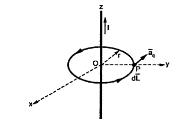
Figure 4. Field intensity of straight conductors
Consider an infinitely long straight conductor which is placed along z-axis carrying direct current I as shown in figure. Consider the Amperian closed path enclosing the conductor as shown in figure. Consider point P on the closed path at which  is obtained. The radius of the path is r from the conductor. The magnitude of
  depends on r and the direction is always tangential to the closed path. So,
  has only component in
  direction say H
  .
.
Consider elementary length  at point P in cylindrical co-ordinates it is r d
 in
in  .
.
 = Hɸ
= Hɸ ɸ and
ɸ and  = r dɸ .
 ɸ
ɸ
 .
.  = Hɸ
= Hɸ ɸ . r dɸ .
 ɸ = Hɸ r dɸ
According to Ampere’s circuit law ,
 = I
= I
 ɸ . r. dɸ = I
Hɸ . r  . dɸ = I
Hɸ .r [2π] =I
Hɸ = 1/ 2π r
Hence  at point P is given by
 = Hɸ.
= Hɸ.  ɸ = 1/ 2 π r .
 ɸ
ɸ
Key Take Aways:
This law states that the integral of magnetic field density (B) along an imaginary closed path is equal to the product of current enclosed by the path and permeability of the medium.
The circulation of a vector field around closed path is given by curl of vector. Mathematically it is defined as
Curl of  = lim ∆ SN ->0
  . d
. d
 N = Area enclosed by the line integral in normal direction
Thus, maximum circulation of  per unit area tends to zero whose direction is normal to the surface is called curl of
  .
.
Symbolically it is represented as
 x
x  = curl of
Key Take Aways:
Vector calculus is concerned with differentiation and integration of vector fields, primarily in 3-dimensional Euclidean space
The stokes theorem relates the line integral to a surface integral. It states that the line integral of  around a closed path L is equal to the integral of curl
  over the open surface S enclosed by the closed path L.
Mathematically it is expressed as,
 . d
. d =
=  x
x  . d
. d
Where dL = Perimeter of total surface S
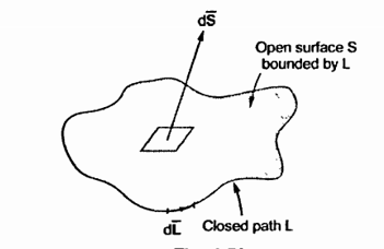
Figure 5. Line Integral.
Key Take Aways:
Stoke’s theorem is applicable only when  and
and  x
x  are continuous on the surface S.
Magnetic flux is defined as the number of magnetic field lines passing through a given closed surface. It provides the measurement of the total magnetic field that passes through a given surface area.
Magnetic Flux Symbol
- Magnetic flux is commonly denoted using Greek letter Phi or Phi suffix B.
- Magnetic flux symbol: Φ or ΦB.
ɸB = B. A . Cos 
Where,
- ΦB is the magnetic flux.
- B is the magnetic field
- A is the area
- θ the angle at which the field lines pass through the given surface area.
Magnetic flux density
Magnetic flux density(B) is defined as the force acting per unit current per unit length on a wire placed at right angles to the magnetic field.
- Units of B is Tesla (T) or Kgs−2A−1
- B is a vector quantity
B=FIl Where, l=length of wire F=total force acting on the wire I=current flowing through the wire.
Key Take Aways:
Magnetic Flux Density is amount of magnetic flux through unit area taken perpendicular to direction of magnetic flux. The total number of magnetic field lines passing through a given area normally is called magnetic flux.
Let us consider the magnetic field is due to electromagnet that is a coil of several no. Turns.
This coil or inductor is carrying current I when it is connected across a battery or voltage source through a switch.
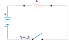
Figure6. Inductor circuit
Suppose battery voltage is V volts, value of inductor is L Henry, and current I will flow at steady state.
When the switch is ON, a current will flow from zero to its steady value. But due to self- induction a induced voltage appears which is
E = -L dI/dt ---------------------------------------------------------------------(1)
Here E always in the opposite direction of the rate of change of current.
The energy or work done due to this current passing through this inductor is U.As, the current starts from its zero value and flows against the induced emf E, the energy will grow up gradually from zero value to U.
dU = W.dt, where W is the small power and W = – E.I
So, the energy stored in the inductor is given by
DU = W. Dt = -E .I dt = L dI/dt .I dt = LIdI
Now integrate the energy from 0 to its final value.
U =  =
=  dI = ½ LI 2
Again
L =  o N 2 A /l
Where N is the number of turns of the coil, A is the effective cross-sectional area of the coil and l is the effective length of the coil.
Again,
I = H.l/N
Where, H is the magnetizing force, N is the number of turns of the coil and l is the effective length of the coil.
I = B.l/ 
Now putting expression of L and I in equation of U, we get new expression i.e.
U = μoN2 A /l . B.L/ μo N / 2 = B 2 Al/ 2 μo
Key Take Aways:
The energy stored in a magnetic field is equal to the work needed to produce a current through the inductor.
Ampere’s law of force is the “law of action” between current carrying circuits through magnetic field.
Consider two parallel wires carrying current in the same direction. It will attract.The force acting on a current element I2 dl2 by a current element I1 dl1 is given by
 12 = μo/ 4π I2
  x I1
x I1  x I1
x I1  x
x  R12 / R 212
The total force acting on a circuit C2 having a current I2 by a circuit C1 having current I1 is given by
 =
=  I1 I2 / 4
  x
x  x
x  R 12 / R 212
Similar to Coulomb’s law, magnetic field can be introduced
Where
 = μo/4π
 x
x  R12 / R 212 T
An infinitely small current immersed in a region of magnetic flux density B experiences a force df
 = I
= I  x
x 
Key Take Aways:
The force of attraction or repulsion between two current-carrying wires is often called Ampère's force law.
Define a vector quantity A whose curl is equal to the magnetic field.
B=curl A=∇×A-----------------------------------------(1)
Eq(1) does not define A uniquely. For, if ψ scalar quantity then add ∇ψA without affecting B, because ∇×∇ψ=curl grad ψ=0∇×∇ψ=curl grad ψ=0.
The vector A is called the magnetic vector potential.
Key Take Aways:
Magnetic vector potential is a vector field that serves as the potential for the magnetic field. The curl of the magnetic vector potential is the magnetic field.
Electric circuit | Magnetic circuit |
The path traced by the current is known as electric current | Path traced by the magnetic flux is called as magnetic circuit. |
EMF is the driving force in the electric circuit. The unit is volts | MMF is the driving force in the magnetic circuit. The unit is ampere turns |
The current I in the electric circuit is measured in amperes | There is flux ɸ in the magnetic circuit which is measured in weber |
The flow of electrons decides the current in conductor | The number of magnetic lines of force decides the flux. |
Resistance R opposes the flow of current. The unit is Ohm | Reluctance (S) is opposed by magnetic path to the flux . The unit is ampere turn/weber |
R =  | S = 1/ μoμra |
I= EMF/ Resistance | Flux = MMF/Reluctance |
Key Take Aways:
The magnetic flux is analogous to the electric current.
References
- Electromagnetic Field Theory Book by A.V.Bakshi
- Engineering Electromagnetics with CD Book by John Buck and William H. Hayt
- Electromagnetic theory Book by Oliver Heaviside
- Electromagnetic field theory Book by Markus Zahn
- Field and wave electromagnetics Textbook by David K. Cheng