Unit 4
Reflections and Refractions
Normal incidence
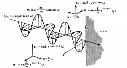
A uniform plane wave with x-directed electric field is normally incident upon a perfectly conducting plane at z=0 as shown in figure.
 Figure 1. Unifrom plane with normal incidence |
The presence of the boundary gives rise to a reflected wave that propagates in z-direction. There are no fields within the perfect conductor. The incident fields travelling in the +z direction can be written as
Ei(z,t) = Re(  e j(wt-kt) ix ------------------------------------------(1)
Hi(z,t) = Re ( / no e j(wt -kx) iy
While the reflected fields propagating in the -z direction are similarly
Er(z,t) = Re ( e j(wt-kt) ix)
Hr(z,t) = Re ( - / ղo e j(wt-kt) iy) ------------------------------------------(2)
Where in the lossless free space
ղo = √  /
/  o
o
k = w √ ---------------------------------------------------------(3)
The total electric and magnetic fields are just the sum of the incident and reflected fields. The only unknown parameter E, can be evaluated from the boundary condition at z =0 where the tangential component of E must be continuous and thus zero along the perfect conductor:
 +
+  = 0 ---
 = -
= -  --------------------------------------------(4)
The total fields are then sum of incident and reflected fields
Ex(z,t) = Ei(z,t) + Er(z,t)
= Re [  ( e -jkz – e jkz ) e jwt]
= 2Ei sin kz sin wt
Hy(z,t) = Hi(z,t) + Hr(z,t)
= Re (  (e -jkz + e jkz ) e jwt) -----------------------------------(5)
= 2Ei/ղo cos kz cos wt
Oblique
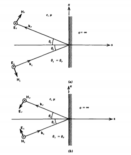
In Figure (a) we show a uniform plane wave incident upon a perfect conductor with power flow at an angle  , to the normal. The electric field is parallel to the surface with the magnetic field having both x and z components:
Ei = Re [  ( e -j(wt -kzlx ) iy]
Hi = Re [  (- cos
  ix + sin
  ix ) e j(wt-kzix-kziz) ] ----------------------(1)
Where
Kxi = k sin  i
i
Kzi = k cos  i k = w√
 , ղ = √ μ/
 ----------------(2)
Because there are no fields within the perfect conductor these boundary conditions at z =0 are
 Figure 2. (a) Electric field polarized parallel to the interface. (b) Magnetic field parallel to the interface.
|
 e -jkzix +
  e-jkzix=0
=  /
/  (
( sin
sin  e -jkzix +
  sin
sin  e-jkzix=0 -------------------------------------(5)
The reflected field amplitude is then
 =
=  .
.
Key Take Aways:
If a planewave incidents normally on a perfect metal with impedance equal to 0, reflection coefficient is equal.
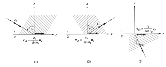
When the plane is obliquely at an angle incident on a plane interface between two media the formation of boundary conditions becomes more complex when incidence is normal. Part of the incident energy is reflected back into medium 1 of parameters  and μ1 and part is transmitted into medium 2 of parameters
  and μ2. The direction of propagation of reflected wave makes the same angle with the normal to the interface as the incident wave. The transmitted wave is the refracted wave.
 |
Figure. Equiphase planes and the directions of propagation of the incident, reflected and refracted waves.
The figure shows equiphase planes and direction of propagation of incident,reflected and refracted waves. These planes in medium1 are moving with velocity c1= 1/ √ and in medium2 with velocity c2= = 1/ √
 .
.
The velocity of the incident and reflected wave is c1/sin  and c1/sin
  and the refracted wave c2/sin
  . To satisy this condition
  =
=  .
.
Sin  / sin
/ sin  = c1/c2 = √
 /√
/√
This is known as Snells law and c1/c2 is termed as index of refraction.
Key Take Aways:
Normal components of D and B are continuous across a dielectric interface. Tangential components of E, H are continuous across a dielectric surface
The electric field confined to small depth at the conductor interface known as the skin depth. We define surface impedance as the ratio of the parallel component of electric filed that give rise to current at the conductor surface
Zs = E||/ Ks where Ks is the surface current density.
Assuming that current flows over skin depth the current density is given by
J = Jo e - z
z
Since the current density has been taken to decay exponentially we extend the integration to infinity and get
Ks =  e -
e - z dz = Jo/
The current density at the surface is written as  E||. For good conductor we have
 = √ iwμ
 + w 2 μ
 ≈ (1+i) √ wμ
 /2
/2
Thus
Zs = E||/ Ks =  /
/ = √wμ/2
 (1+i) = 1/
  (1+i) = Rs +iXs
Key Take Aways:
The surface impedance is given as the ratio of the voltage to current.
Poynting theorem states that the net power flowing out of a given volume V is equal to the time rate of decrease of stored electromagnetic energy in that volume decreased by the conduction losses is the total power leaving the volume = rate of decrease of stored electromagnetic energy ohmic power dissipated due to motion of charge.
Proof:
The energy density carried by the electromagnetic wave can be calculated using Maxwell's equations
Div  = 0 -----------------------------(i)
Div  = 0 ---------------------------------(ii)
Curl  = - ∂ B / ∂t -----------------------------------(iii)
And curl  =
=  + ∂
+ ∂  / ∂t
/ ∂t
Taking scalar product of (iii) with H and (iv) with 
That is  curl
curl  = -
= -  . ∂
. ∂  / ∂t --------------------------------------(iv)
 curl
curl  =
=  .
.  +
+  . ∂
. ∂  / ∂t ----------------------------------------(v)
So div ( x
x  ) = - [
  ∂
∂  / ∂ t +
  ∂
∂  / ∂ t] -
  .
. 
But  = μ
= μ and
and  =
= 
So  ∂
∂  / ∂ t =
  ∂
∂  )/ ∂ t = ½ μ ∂/∂t (H 2)
= ∂/∂t [ ½  .
.  ]
]
And  ∂
∂  / ∂ t =
  ∂ / ∂ t ( μ
 ) = ½ μ ∂ / ∂ t (H 2 )
= ∂ / ∂ t (1/2 . .
.  )
)
And  ∂
∂  / ∂ t =
  ∂ / ∂ t (
  ) = ½
) = ½  ∂ / ∂ t (E 2 ) = ∂ / ∂ t [ ½
  .
.  ]
]
So from equation div (  x
x  ) = - ∂ / ∂ t [ ½
  .
.  .
.  ] -
] -  .
. 
 .
.  = - ∂ / ∂ t [ ½
  .
.  .
.  ] – div (
 x
x  )
)
Integrating equation over a volume V enclosed by a surface S
 dV = - |∂ / ∂ t [ ½
  .
.  .
.  | dV -
  ((
(( x
x  ) dV
) dV
Or  dV = -
 H 2 + ½
  E 2 ] dV -
  ((
(( x
x  ) ds
) ds
As  = μ
= μ =
=  and
and  Ucm / ∂t dV -
  x
x  .ds
.ds
Or -  x
x  .dV = - ∂/∂t
  ½[ μ H 2 + ½
  E 2] dV -
  ds
ds
Or  ds = -
  Ucm / ∂t dV -
  x
x  .dV
.dV
Or  ds = - -
  Ucm / ∂t dV -
  x
x  .dV
.dV
That is the Total power leaving the volume = rate of decrease of stored e.m.f energy - ohmic power dissipated due to charge motion
This equation represents the poynting theorem according to which the net power flowing out of a given volume is equal to the rate of decrease of stored electromagnetic energy in that volume minus the conduction losses.
For E and H which are varying sinusoidally, it is rather useful to have the average power density. Writing explicitly for the time harmonic function we have
E(x,y,z,t) = Eo(x,y,z) e jwt
H(x,y,z,t) = Ho(x,y,z) e jwt
The average Poynting vector(average over the time period) is
Pav = ½ Re ( E x H *)
The average power density is a much meaningful quantity as it gives the actual power flow at that location. The instantaneous power on the other hand does not correctly represent the power flow as it can be negative or positive. It can probably then give the amount of power oscillating back and forth around a point plus the actual power flow at that point.
For a real power flow, two conditions should be satisfied.
(1) E and H fields should cross each other
(2) E and H should not be in time quadrature that is 90 out of phase with each other. E and H fields which are parallel and/or in time quadrature do not constitute any power flow.
Key Take Aways:
The Poynting theorem should read rate of change of energy in the fields = negative of work done by the fields on the charged particles minus the Poynting vector term.
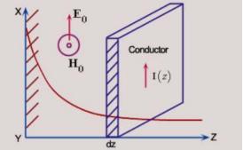
The resistance of the slab along the direction of the current is
DR =  l /A = 1/
  dz
dz

Figure2. Resistance of the slab
The ohmic loss in the slab is
DW = |I(z)| 2 dR
Substituting for I(z) we get
DW = |  Eo e –
  z dz| 2 . 1/
  dz
dz
=  |Eo| 2 e -2αz dz
The total loss per unit area of the conductor surface therefore is
W =  |Eo| 2e -2αz dz
=  |Eo| 2 [ e -2αz / -2 α] 0∞
W =  |Eo| 2 / 2α =
  |
| | 2/
| 2/  2 |Js| 2
Substituting for  and α, the loss per unit area of the conducting surface is
W= Rs|Js| 2
The power loss is proportional to the surface resistance which increases with frequency and decreases with conductivity. Higher the conductivity lesser the loss and for ideal conductor when the conductivity is infinite the ohmic loss is zero.
Key Take Aways:
The power loss is proportional to the surface resistance which increases with frequency and decreases with conductivity.
References:
- Electromagnetic Field Theory Book by A.V.Bakshi
- Engineering Electromagnetics with CD Book by John Buck and William H. Hayt
- Electromagnetic theory Book by Oliver Heaviside
- Electromagnetic field theory Book by Markus Zahn
- Field and wave electromagnetics Textbook by David K. Cheng