Unit – 1
Introduction to signals
A signal is a function representing a physical quantity as a variable, and typically it contains information about the behaviour or the nature of the phenomenon, for instance in a RC circuit the signal may represent voltage across the capacitor as the current flowing through the resistor.
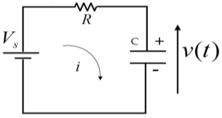
Fig: RC circuit
Mathematically a signal is represented as a function of independent variable ‘t’. Usually ‘t’ represents time. Thus, the signal is denoted by x(t).
1) Continuous time signal:
x(t)=cosωt
The functions that are defined for every value of time is defined as continuous time signal. The time is taken between the limits because the value between infinity at some time is not measurable.
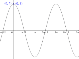
Fig continuous time signal
2) Discrete time signal:
If a discrete variable x(t) is defined at discrete time then x(t) is a discrete time signal. A discrete time signal is often identified as a sequence of number denoted by x(n), where ‘n’ is an integer.
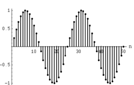
Fig: Discrete time signal
3) Even and odd signal: The even signals are symmetrical about Y-axis. They lie in first and second quadrants.
x(-t) =x(t)
x[-n] =x[n]
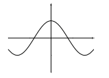
Fig: Even signal
The odd signals are symmetrical about origin. They lie in first and third quadrants.
x(-t) = -x(t)
x[-n] = -x[n]
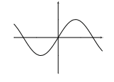
Fig: Odd signal
A signal having even and odd parts is mixed signal.
y(t)=sint + cost
y(t)=x0(t)+xe(t) (1)
From y(t) we can find odd and even parts by substituting t=-t in above equation
y(-t) =x0(-t) +xe(-t) (2)
y(-t) = -x0(t)+xe(t) (3)
Adding 1 and 3
 = xe(t)
 = x0(t)
x0(t)=
xe(t)=
4) Periodic and Non-periodic signals:
A signal which repeats itself after a particular period of time is called as Periodic signal.
x(t+T)=x(t)
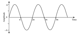
Fig: Periodic signal
A non-periodic signal is one which does not repeat itself after a particular interval of time.
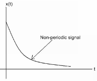
Fig: Non-Periodic signal
5) Energy and Power signal:
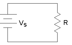
The power for above circuit with R=1Ω is given as
P= 
For R=1Ω
P=V2(t)=I2(t)
This is known as normalized power.
Total energy E= dt Joules
E=
Energy of periodic signal is always infinite.
Now calculating power P=
P= dt
dt
P= dt Watts
Power for Non-periodic signal is always zero.
1) Linear and Non-Linear system:
A system is said to be linear when it obeys law of superposition.
If we have two inputs x1(n) and x2(n), and output y(n). The operator ‘H’ is called linear operator if it satisfies the following condition.

In the above figure first the two inputs pass through an adder than through the operator. So, the equation after adder will be ax1(n)+bx2(n). Now final output equation after passing through operator is
Y(n)=H[ax1(n)+bx2(n)] =Hax1(n)+H bx2(n)
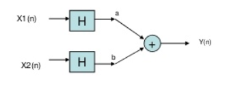
Now, in above figure the two inputs first pass through the operator and then through the summer. The equation at output is
Y(n)= Hax1(n)+H bx2(n)
The two output equations in both the systems are same. Hence, the system operator H is linear.
Non-Linear system: If the system does not obey law of superposition, it is said to be non-linear.
2) Time variant and Time Invariant system: A time delay or advance in the input signal produces the corresponding change in the output. Then the system is said to be time invariant.


Fig: Time-Invariant system
If the delay or advance in the system does not produce corresponding change in the output then it’s called as Time variant System.
3) Causal and Anti-Causal system: A system is said to be causal if it’s output at any point of time depends only on the input x(t) for time ‘t’, where t<t0, where t0 is the present time. If not so then it is called as anti-causal system.
Only causal signals are realisable signals.
4) Memory and Memoryless System: A system is said to be memoryless if at any point of time the output depends only on present input but not on its past inputs.
If the system output at instance of time depends on the past inputs then it is called as memory system.
5) Invertible and Non-Invertible system: The system is said to be invertible if the input of the system can be recovered from the system output.
Que) For the system with y(t)=x(-t), find whether the system is linear or not?
Sol: To comment on linearity of system it should follow law of superposition. So. From model given below

Y(t)=ax1(-t)+bx2(-t)
Now from second model
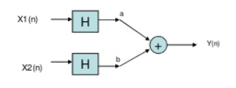
Y(t)= ax1(-t) +bx2(-t)
Since, output from both the model is same so system is linear.
Que) For y(t)=cos[x(t)], comment whether it is time invariant or not?
Sol: From model 1

Y(t)=cos[x(t-t0)]
From model 2

Y(t)=cos[x(t-t0)]
Since, time delay or advance in the input signal produces the corresponding change in the output. Hence, it is time invariant.
Que) For y(t)=x(t2), is the system causal or anti causal?
Sol: y(t)= x(t2)
If the output for any time depends on the future than its not causal. So, Let t=1
Y (1) =x (1)
t=2
y (2) =x (4)
Since, it depends on future values, so it is anti-causal.
Que) For y(t)=x(t)+2. Comment whether system has memory or memoryless?
Sol: For t=1
Y (1) =x (1) +2
For t=2
Y (2) =x (2) +2
So, for any value of t the output depends only on present input. Hence, it is memoryless.
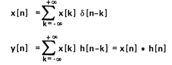
1) Convolution sum:
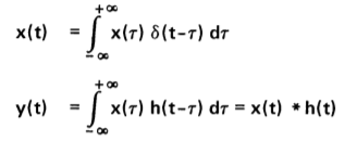
2) Convolution Integral:
3) Commutative Property:
x*h=h*x
4) Associative Property:
x*[h1*h2] = [x*h1] * h2
5) Distributive Property:
x*[ h1+h2] = [x*h1] + [x*h2]
6) Causality:
x[n]=0 for n<0
7) Stability:
 <∞
<∞
8) Memoryless:
If x[n]=0 for all n≠0
9) Invertibility:
A system is said to be invertible if there exists an inverse system which when connected in series with the original system produces an output identical to input.
(x* )[n]=x[n]
(x*h*h-1) [n]=x[n]
(h*h-1) [n]=
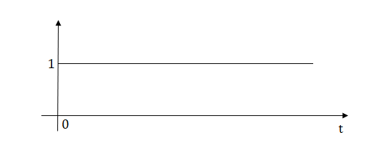
1) Step Function:
U(t)=1 t≥0
=0 t<0
L[u(t)] = =
= =
=
2) Pulse Function:
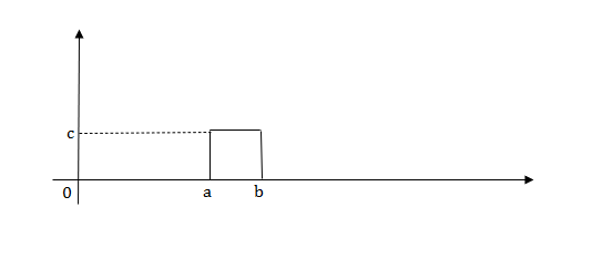
L[u(t)] = =
=
f(t)<—>F(s)
f(t-a) = F(s)
F(s)
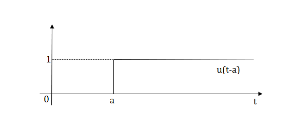
L[u(t-a)] =
Ramp function:
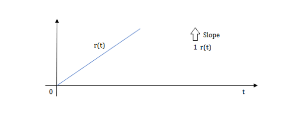
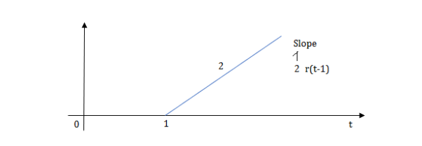
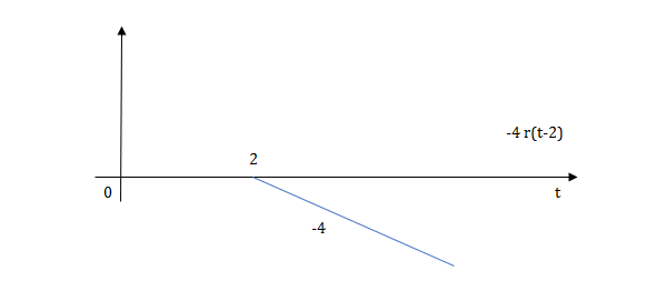
R(t)=tu(t)
L[tu(t)] = dt=
dt=
It is a technique for solving differential equations. The time domain differential equations are transformed into algebraic equation of frequency domain. After solving the algebraic equation in frequency domain, the result then is finally transformed to time domain form to achieve the ultimate solution of the differential equation.
The Laplace Transform is given as
F(s)= dt
dt
The advantages of Laplace Transform are:
1) It is systematic.
2) It gives total solution (transient and sustained solution) in one operation.
3) The initial conditions are automatically specified in the transformed equations.
Note: There are many functions which do not have Laplace Transforms. These functions are not generally used in analysis of linear systems. But some conditions can be defined to get Laplace transformation of such functions. The Dirichlet condition defines the necessary condition for transformation of some functions such as:
a) The function should be continuous. The function should be single-valued.
b) The function must be of exponential order.
Properties of Laplace Transform:
1) Linearity Property:
If f1(t) and f2(t) are two functions of time. Then, in domain of convergence
L[a f1(t)+b f2(t)]=a + b
+ b
=aF1(s)+bF2(s)
2) Differentiation Property:
If x(t) is function of time then Laplace transform of nth derivative is given as
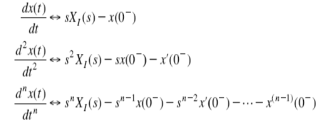
3) Integration Property:
The Laplace of nth order integral is given as
L [ ]=
]= +
+
L[f-n(t)]= +
+ +
+ +……….
+……….
As 
 ……...=0. Hence
L[f-n(t)] =
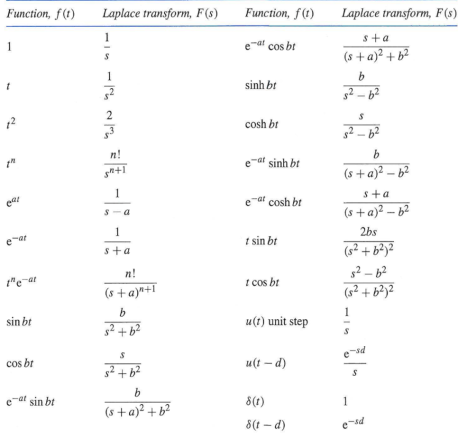
Laplace Transform of some common functions
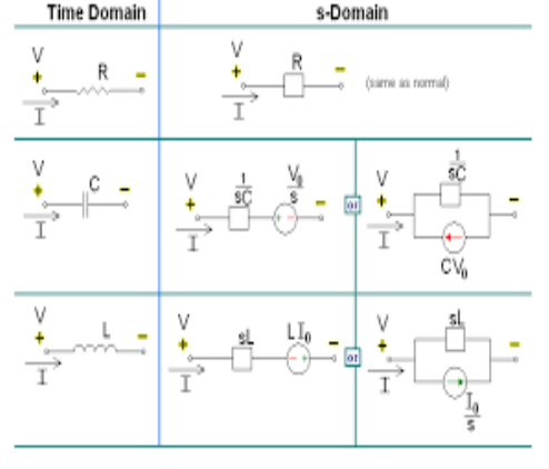
Application of Laplace Transform in Electrical Circuits
Ques: - Find Vc (0) for given circuit
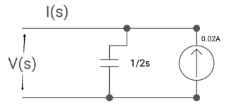
Soln: - By Laplace transform

C=2F
CVc (0) =0.02A
Vc (0) =0.02/2=0.01A
Que: -
Diagram
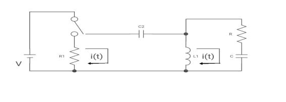
(a) switch is at before moving to position = at t= 0, at t= 0+, i1(t) is
(a) –V/2R (b) –V/R (c) – V/4R (d)0
Soln: -
i1(t) L.T I1(s)
i2(t) L.T I2(s)
Then express in form
[ I1(s)/I2(s)] [:] = [:]
Drawing the circuit at t = 0-
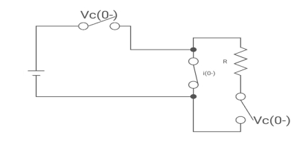
:. The capacitor is connected for long
Vc1(0-) = V
iL (0-) =0
Vc2(0-) =0
At t= 0+
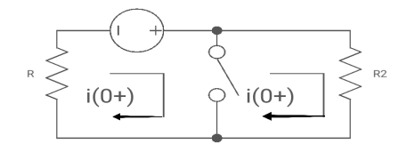
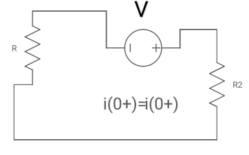
i1 (0+) = -V/2R
For t>0 the circuit is
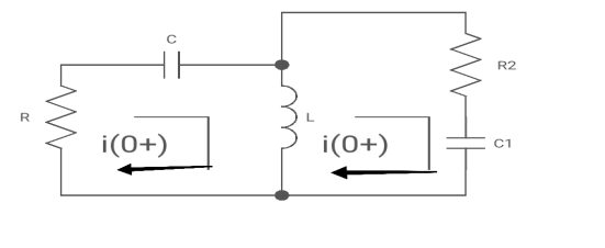
Apply KVL
-R i1(t) -1/c  dt -L
dt -L =0
=0
Also, we can deduce i1(t)- i2 (t) = iL(t)
-Ri1(t) -1/c  - L
- L = 0
= 0
-RI1(s)-[ -
- ]-L[sI1(s)-iL (0-)] =0
- RI1(s)- -
-  -s L I2(s)=0
 - s L I2(s)= -
  (1)
(1)
Again
-Ri2(t)) -1/c  dt -L
dt -L =0
=0
-Ri1(t) -1/c  - L
- L = 0
= 0
Taking Laplace Transform
-RI2(s)- [ -
- ]- L [s IL(s)- iL (0-)] =0
-RI2(s)-  -
- Ls [ I1(s)- I2(s)] =0
 - s L I1(s)=0 (2)
Hence in matrix representation

 =
= 
Ques: -
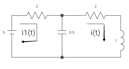
All initial conditions are zero i(t) L.T I(s) , then I(s)will be?
Sol: Drawing Laplace circuit
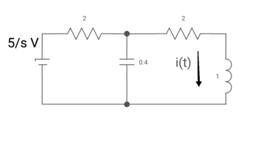
(2+5) 11 2/5
Zeq= 2(5+2)/S2+2S+2
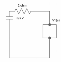
V1(s) = 5/S*2(S+2)/S2+2S+2
=10[(S+2)/S]/[2(2S+S2+2) +2(S+2)]
V1(s) = [5(S+2)/S]/S2+ 3S +4
I(s) = V1(s)/5+2 =(5/S)/(S2+3S+4)
Reference
- Engineering Circuit Analysis”, by W H Hayt, TMH Eighth Edition
- “Network analysis and synthesis”, by F F Kuo, John Weily and Sons, 2nd Edition.
- “Circuit Theory”, by S Salivahanan, Vikas Publishing House 1st Edition, 2014
- “Network analysis”, by M. E. Van Valkenburg, PHI, 2000
- “Networks and Systems”, by D. R. Choudhary, New Age International, 1999
- Electric Circuit”, Bell Oxford Publications, 7th Edition.