Unit – 3
Graph theory
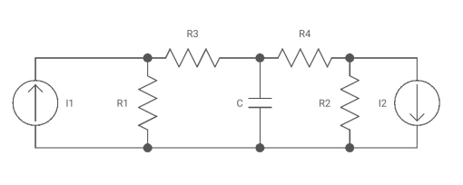
Node: Node is a point joining two or more than two elements
n = no of nodes
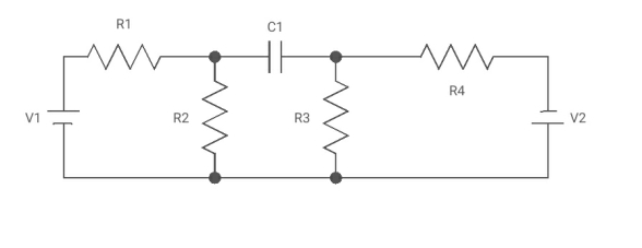
Branch: Element with nodes at both the ends
b = total no of branches
b = 7
Graph: If all the elements (R, L, C) of any electrical Circuit are replaced by a line than it becomes graph
Voltage source will be short circuited and amount source will be open circuited
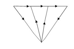
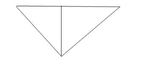
Oriented Graph: Graph with direction of amount
Tree: It includes all nodes of graph and (n-1) branches without making any closed path
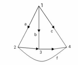
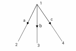
Twig: Branches of free are called twigs. If is no. Of nodes of a graph then no. Of twigs are n-1
For any electrical at no. Of twigs are equal to no. Of possible nodal equations.
Cotree: Remaining part of free. Shown by dotted lines.
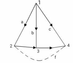
Links or chords : Branches of cotree are called links or chords. If n is no. Of nodes and b is no. Of branches of graph then no. Of links or chords denoted by L.
L = b – n + 1
For any electrical circuit no. Of loop equations are equal to no. Of twigs
Que. Find total possible no. Of trees?
T = n (n-2)
n = no. Of nodes
T = 6 (6-2) = 6 4
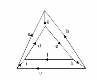
Orientation of f- cut set as same as direction of current in twig associated with cut – set
It gives information about branch voltage
Tie – set: It is collection of branches that includes only one link and number of twigs
f- tie set: collection of branches that includes one link and minimum number of twigs.
f- tie set: It is mathematical representation of f-tie set in form of matrix with all the branches of graph as column and all the T-Set (loop) as rows.
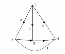
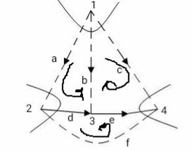
The orientation of T-Set is same as direction of everent in the link associated with T-Set
Construction of Dual Network
Some important duals are given below.
Loop | Node | Loop | Node |
Current | Voltage | Number of Loops | Number of nodes |
Inductance | Capacitance | Link | Tree branch |
Resistance | Conductance | Link current | Tree branch voltage |
Branch Current | Node Voltage | Tree branch current | Link voltage |
Mesh or Loop | Node or pair | Tie Set | Cut Set |
Loop Current | Node pair Voltage | Short Circuit | Open Circuit |
Mesh Current | Node Potential | Parallel path | Series path |
|
|
|
|
Steps for construction of Dual Network:-
i) In each loop place a dot. This internal dot corresponds to independent node in the dual network.
Ii) Outside network place a dot. This is called datum node is dual network
Iii) Connect all the adjacent loops by dashed lines crossing comman branches.
Iv) In dual network this common branch is replaced by its dual element.
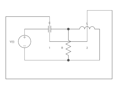
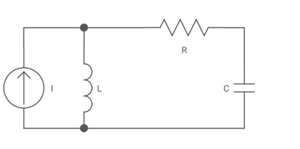
Incidence Matrix :- Mathematical representation of graph in form of matrix that includes all the branches as column and all the nodes as rows.
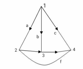
Sum of all the elements for any column of incidence matrix is zero.
Reduced Incidence Matrix :-
If we remove any one of the row from incidence matrix then it becomes reduced incidence matrix is (n-1) X b
Cut set: Collection of branches that includes only one twig and number of links.
Fundamental Cut set / f- cut set: -
It is collection of branches that includes one and only one twig and minimum number of links.
f- cut set matrix: -
It is mathematical representation of f-cut set in form of matrix with branches of graph as column and cut set as rows.
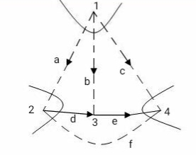
Va Vb Vc Va Ve Vf
a b c d e f
C1 (Vb) 1 1 1 0 0 0
C2(Vd) -1 0 0 1 0 -1
C3(Ve) 0 0 1 0 1 -1
Vb-Vd Vb Vb+Ve Vd Ve -Vd-Ve
1 Relationship of two-port variables
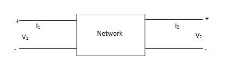
2 Port networks

1 port network

3 port network
z-parameter  open circuit impedance
y-parameter  short circuit admittance
h-parameter  hybrid parameter
g-parameter  inverse hybrid parameter
ABCD-parameter  transmission parameter
A’B’C’D’ parameter  inverse transmission
s-parameter  scattering
Used for very high frequency application
Relationship of Two-Part Variables
Condition for Reciprocity and Symmetry
Sr No. | Parameter | Reciprocity | Symmetry |
1. | Z Parameter | Z12 = Z21 | Z11= Z22 |
2. | Y Parameter | Y12 = Y21 | Y12 = Y21 |
3. | h Parameter | h12 = h21 | Δ = 1 |
4. | ABCD Parameter | AD-BC = 1 | A = D |
5. | Inverse h Parameter | g12 = g21 | Δ = 1 |
6. | Inverse Transmission | A1D1 – B1 C1= 1 | A1 = D1 |
Relation between Two- Port Parameters: -
Δ = X11 X22 – X12 X21, ΔT = AD – BC
| [z] | [y] | [h] | [T] |
[z] | Z11 Z12 | y22 – y12  
| Δh – h12   | A – ΔT   |
Z21 Z22 | y21 – y11  
| -h21 h  
| 1 D   | |
|
|
|
|
|
[y] | Z22 -Z12  
| y11 y12 | 1 -h12  
| D – ΔT   |
-Z21 Z11   | y21 y22 | h21 Δn   | -1 A  
| |
|
|
|
|
|
[h] | Δz Z12  
| 1 -y12  
| h11 h12 | B ΔT   |
-Z21 -1   | y21 Δy   | H21 h22 | -1 C  
| |
[T] | Z21 ΔZ   | -y22 -1   | -Δh -h11  
| A B |
1 Z22  
| -Δy -y11  
| -h22 -1   | C D |
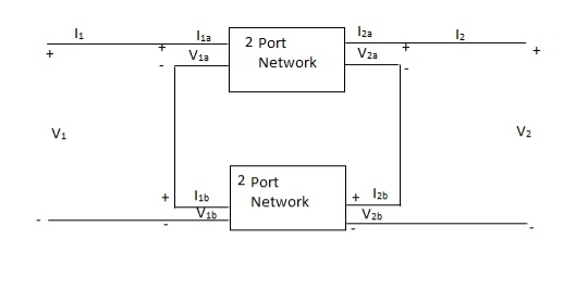
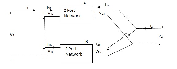
V1 = V1a +V1b
I1 = I1a = I1b
V2 = V2a +V2b
I2 = I2a = I2b
 =
= 
 =
= 
 =
= 
Parallel connection
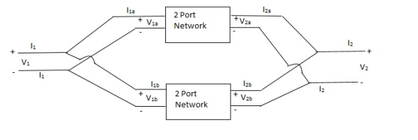
V1 = V1a = V1b
 =
= 
 =
= 
 =
= 
Series parallel connection
I1 = I1a = I1b
V1 = V1a +V1b
If two 2-ports are connected in series parallel then overall h-parameter is sum of individual h-parameter
 =
= 
Parallel series connection
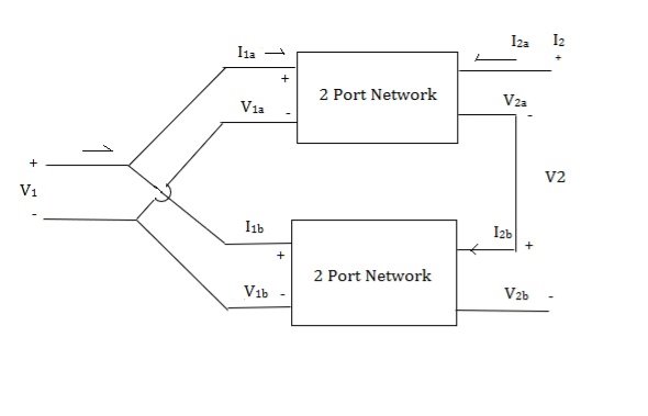
 =
= 
Cascade connection

V1 = V1a, V2a = V1b , V2 = V2b
I1 = I1a , I2a = -I1b , I2 = I2b
Transmission parameter for N/W (A)

Transmission parameter for N/W (B)

Overall transmission parameter

Que 1.
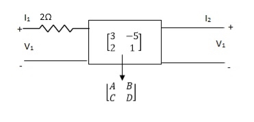
Find out overall transmission parameter?
Solution:
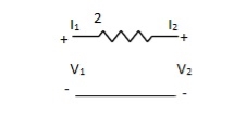


Que 2.
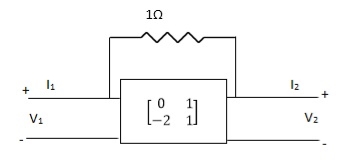
Find overall Y-parameter?
Solution:


Short circuit Admittance parameters
Y-parameter: -
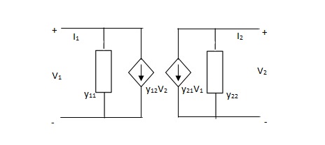
I1 = Y11V1 + Y12V2
I2 = Y21V1 + Y22V2

Y11 =  V2=0
V2=0
Y12 =  V1=0
V1=0
Y21 =  V2=0
V2=0
Y22 =  V1=0
V1=0
V1& V2 should be independent
Equivalent circuit: -
Symmetrical two port N/W: -
 I2 = 0 =
  I1=0
I1=0
Y12 = Y22
Reciprocal two port N/W: -
 I1=0 =
 I2 = 0
Y12 = Y21
Que 1.
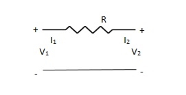

Solution: V1 – I1R – V2 = 0
V1 – V2 = I1R
I1 =  V1 -
V1 -  V2
V2
V2 = I2R + V1
I2 = -  V1 +
V1 +  V2
V2
Y11 = 
Y12 = Y21 = 
Y22 = 
Que 2.
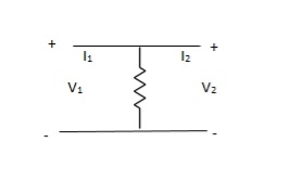
Solution: Y-parameter does not exist as V1 = V2
Que 3.

Solution: I1 = V1Ya + (V1 – V2)Yc
I1 = (Ya + Yc)V1 - YcV2
I2 = V2Yb + (V2 – V1) Yc
I1 = (Yb + Yc) V2 - YcV1
Y11 = Yb + Yc
Y12 = Y21 = - Yc
Y22 = Yb + Yc
Que 4.
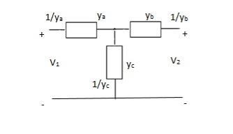
Solution:
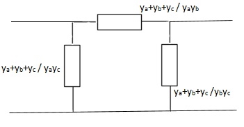
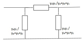

Que 5:
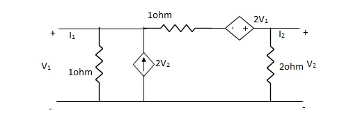
Find Y-parameter?
Solution:
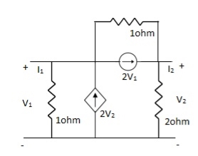
-I1 +  – 2V2 +
  + 2V1 = 0
I1= V1 + V1 - 3V2 + 2V1
I1= 4V1 - 3V2V
V2 + 2V2- 2V1 = 2(I2 + 2V1)
- 2V1 + 3V2 = 2(I2 + 2V1)
3V2 - 2V1 – 4V1 = 2I2
I2 = -3V1 +  V2
V2
Y11 = 4
Y12 = -3
Y21 = -3
Y22 = 
Open circuit impedance parameters
Z-parameter: -
v1 = Z11I1 + Z12I2
v2 = Z11I1 + Z22I2
 =
= 
Z11 =  I2=0
I2=0
Z12 =  I1=0
I1=0
Z21 =  I2=0
I2=0
Z22 =  I1=0
I1=0
 I1 and I2 are excitations at port 1 & 2 respectively.
 V1 and V2 are the responses at port 1 and 2 respectively.
Equivalent circuit: -

Symmetry: -
 I2=0 =
 I1 = 0
Z11 = Z22
Reciprocal two port N/W: -
 I2=0=
I2=0=  I1=0
I1=0
Z12 = Z21
I1& I2 should be independent
Que 1.
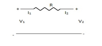
Find Z-parameter
Solution: I1 = -I2
Current dependent so Z-parameter doesn’t exist
Que 2.
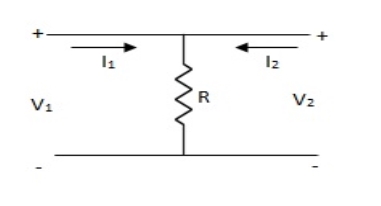
Find z-parameter
Solution: V1 =R (I1 + I2)
V2 = R (I1 + I2)
Z11 = Z12 = Z21 = Z22 = R
Que 3.
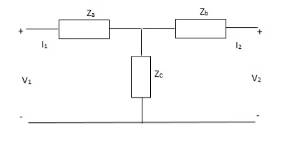
Solution: V1 = I1Za + I1Zc + I2Zc
= (Za + Zc) I1 + ZcI2
V2 = I2Zb + I2Zc + I1Zc
= (Zb + Zc)I1 + ZcI1
Z11 = (Za + Zc)
Z12 = Zc = Z21
Z22 = (Zb + Zc)
Que 4.

Solution: V1 = Za (I1 - I)
(I - I1) Za+ IZc+ Zb (I + I2) = 0
I (Za + Zb + Zc) – I1Za + I2Zb = 0
I = 
V1 = ZaI1 - Za
=  I1 + I2
V2 = Zb (I2 + I)
= ZbI2 + Zb
=  I2 + I2
Z11 = 
Z12 = Z21 = 
Z22 = 
Can be solved by Y-A conversion
Que 1.
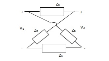
Solution:
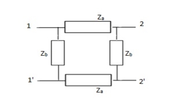
Z11 =  I2=0
I2=0
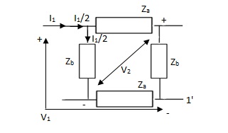
V1 -  (Za + Zb) = 0
 = Z11 =
Z21 =  I2=0
I2=0
V2 -  Zb +
Zb + Za = 0
 =
= 
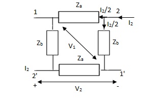
Z12 = 
Z22 = 
Que 2.
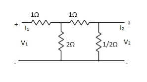
Find Z21?
Solution: Z21 =  I2=0
I2=0
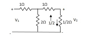
I1/2 = 
=  I1
I1
V2 =  I1/2
I1/2
=  ×
×  I1
I1
=  I1
I1
Z21 =  I2 = 0 =
  I1 Ω
I1 Ω
Que 3.
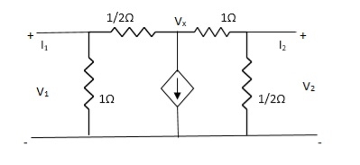
Solution: +
+  + 2V1 = 0
2Vx – 2V1 + Vx – V2 + 2V1 = 0
3Vx = V2
Vx = 
I1 = V1 + 
= 3V1 – 2Vx
= 3V1 – 2
V1 = 
 + 2V2 = I2
3V2 -  = I2
= I2
 V2 = I2
V2 =  I2
I2
V1 = 
= 
Z11 = 
Z12 = 
Z21 = 0
Z22 = 
Transmission parameter [ABCD]
V1 = AV2 - BI2
I1 = CV2 - DI2

A =  I2=0
I2=0
B =  V2=0
V2=0
C =  -I2=0
-I2=0
D =  V2=0
V2=0
Symmetrical two port N/W: -
 I2 = 0 =
  I1=0
I1=0
A = D
Reciprocal two port N/W :-
 I1=0 =
 I2 = 0
AD – BC = 1
Que 1.
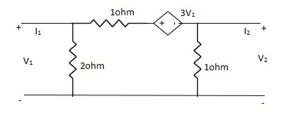
Solution:
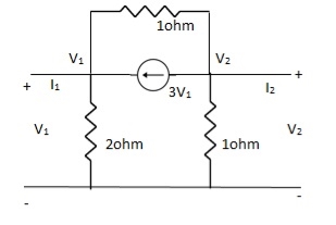
-3V1 – I1 +  +
+  = 0
= 0
 +
+  = I1
= I1
 V1 – V2 = I1
 V1 = V2 + I1
V1= V2-
V2-  I1----------------(1)
I2 = 3V1 + V2 + V2 – V1
I2 = 2V1 + 2V2
2V1 = I2 - 2V2
2V1 = - 2V2 + I2
V1 = -V2 +  I2 ----------------(2)
A = -1
B = 
From (1) & (2)
-V2 +  I2 =
I2 =  I1 -
I1 -  V2
V2
 V2 - V2 +
  I2 =
I2 =  I1
I1
 I1 =
I1 =  V2 + V2 -
  I2
I2
I1 =  V2 -
V2 -  I2
I2
C = 
D = 
Que 2.

Solution: V1 = RI1 + V2 ----------------(1)
I2R = V2 – V1
I2 =  V2 -
V2 -  V1
V1
I2R = V2 – V1
V1 = I2R - V2 --------------------(2)
A = 1
B = R
From (2) in (1)
V2 - I2R = V2 + RI1
I2 = -I1
C = 0
D = 1
Que 3.
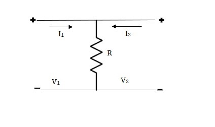
Solution: V1 = R (I1 + I2)
V2 = R (I1 + I2)
V1 = V2 + 0I2
A = 1
B = 0
V2 = RI1 + RI2
RI1= V2 - RI2
I1 =  V2 – I2
C =  , D = 1
Transmission parameter [ABCD]
V1 = AV2 - BI2
I1 = CV2 - DI2

A =  I2=0
I2=0
B =  V2=0
V2=0
C =  -I2=0
-I2=0
D =  V2=0
V2=0
Symmetrical two port N/W: -
 I2 = 0 =
  I1=0
I1=0
A = D
Reciprocal two port N/W: -
 I1=0 =
 I2 = 0
AD – BC = 1
Que 1.
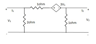
Solution:
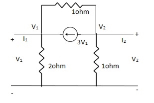
-3V1 – I1 +  +
+  = 0
= 0
 +
+  = I1
= I1
 V1 – V2 = I1
 V1 = V2 + I1
V1= V2-
V2-  I1----------------(1)
I2 = 3V1 + V2 + V2 – V1
I2 = 2V1 + 2V2
2V1 = I2 - 2V2
2V1 = - 2V2 + I2
V1 = -V2 +  I2 ----------------(2)
A = -1
B = 
From (1) & (2)
-V2 +  I2 =
I2 =  I1 -
I1 -  V2
V2
 V2 - V2 +
  I2 =
I2 =  I1
I1
 I1 =
I1 =  V2 + V2 -
  I2
I2
I1 =  V2 -
V2 -  I2
I2
C = 
D = 
Que 2.
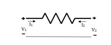
Solution: V1 = RI1 + V2 ----------------(1)
I2R = V2 – V1
I2 =  V2 -
V2 -  V1
V1
I2R = V2 – V1
V1 = I2R - V2 --------------------(2)
A = 1
B = R
From (2) in (1)
V2 - I2R = V2 + RI1
I2 = -I1
C = 0
D = 1
Que 3.
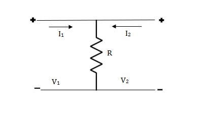
Solution: V1 = R (I1 + I2)
V2 = R (I1 + I2)
V1 = V2 + 0I2
A = 1
B = 0
V2 = RI1 + RI2
RI1= V2 - RI2
I1 =  V2 – I2
C =  , D = 1
The two-port network can be represented in terms of short circuit and open circuit impedances in terms of ABCD parameters. The ABCD parameter is represented as
V1 = AV2 - BI2
I1 = CV2 - DI2
With I2=0
Z1OC= =
= (1)
(1)
With V2=0
Z1SC= =
= (2)
(2)
Similarly, when I1=0 and V1=0, we have
Z2OC= =
= (3)
(3)
Z2SC= =
= (4)
(4)
From all above equations we get
 =
=
 =
=
Hence, 
The ABCD parameters in terms of open and short circuit impedances is given as from equation 1,2,3 and 4
A=
B=
C=
D=
Image impedance in terms of Open and Short circuit Impedances:
Zi1=
Zi2=
Where Zi1 and Zi2 are impedances at input and output network respectively.
 =tanh-1
 = tanh-1
 = tanh-1
For symmetrical network A=D
Z0= Zi1= Zi2= =
=
 = tanh-1
 = tanh-1
As, A=D=cosh
Since, sinh =
= and Z0= Zi1= Zi2=
B= Z0 sinh
C=
Reference
- Engineering Circuit Analysis”, by W H Hayt, TMH Eighth Edition
- “Network analysis and synthesis”, by F F Kuo, John Weily and Sons, 2nd Edition.
- “Circuit Theory”, by S Salivahanan, Vikas Publishing House 1st Edition, 2014
- “Network analysis”, by M. E. Van Valkenburg, PHI, 2000
- “Networks and Systems”, by D. R. Choudhary, New Age International, 1999
- Electric Circuit”, Bell Oxford Publications, 7th Edition.