Unit – 4
Network functions
A) One port Network: -
The one port network can be represented as shown below. It has only one port i.e. input port or only output port.
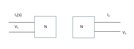 diagram:-
Fig 1) one port networks
1) Driving point impedance at input port
Z11(S) = V1(S) / I1(S)
2) Driving point impedance at output port
Z22(S) = V2(S) / I2(S)
3) Driving point admittance at input port
Y11(S) = I2(S) / V2(S)
4) Driving point admittance at output port
Y22(S) = I2(S) / V2(S)
After studying above equations, it can be clearly that
Z11(S) = 1 / Y11(S) And Z22(S)=1/Y22(S)
B) Two Port Network: -
The network as the name says has two one input and other outout port.
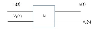
Fig ii) Two port network
1)Transfer Function impedance Z11(S) = V2(S) / I1(S)
2) Transfer admittance function Y12(S) = I2(S) / V1(S)
3) Eworent ratio transfer function Y12(S) = I2(S) / I1(S)
4)Voltage ration transfer function G12(S) / V2(S) / V1(S)
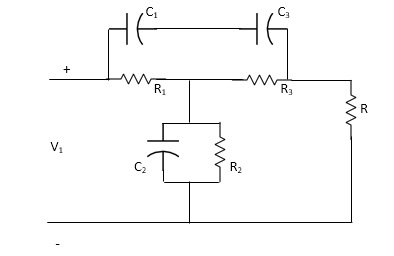
Q1) For the network shown below 1) show that with port 2) open the driving point input impedance 1π) b) find the voltage, ratio transfer function 1/2 for the two-port network.
Diagram: -
Solution: - from above network we take L.T
 diagram: -
Reducing 4 we gel,
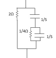 Z1=(25+25*1 / 25+1)*1
25+25*1 / 25+1*1
Z1=4S2+45/452+65+1
Z2=
Z2=(1/4S/1/4+1/5+1/5)*2
1/45/1/4+1/3+1/5+2
=2(5+5+4) / 5+5+4+25(5+4) = 2(25+4)/252+10S+4
Z2=25+4/252+10+4
Applying KVL, in the circuit
V1=I1Z1+I,Z2 -----------1
V2= I1Z2 ...............2
.: V1=I1Z1+V
V1 / I1= (Z1+Z2) (from----1)
Dividing equation 2 by 1
G12=Z 2 / Z1+Z2
Calculating z11 we have,
Z11=Z1+Z2
Z11 = 4S2+4S / 4S2+6S+1 * 2S+4/S2+SS+2
=(4S2+4S)(S2+SS+2)+(2S+4)(4S2+6S+1) / (4S2+6S+1)(S2+SS+2)
Z11=4S4+20S3+8S2+4S3+20S2+8S+8S3+12S2+25+16S2+4 /(4S2+6S+1)(S2+SS+2)
= (4S4+32S3+5652+345+4 / (4S2+6S+1)(S2+SS+2)
G12= Z2 / Z1+Z2
= (2S+4) / (S2+SS+2) / (4S+32S3+56S2+34S+4) / (4S2+6S+1)(S2+SS+)
G12= (2S+4)(4S2+6S+1) / 4S4+32S3+56S2+34S+4
Network function of some network
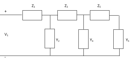
a) Ladder Network: -
For this type of network series are represented as impedance and about cum represent admittance, as shown bellow
 Diagram
Now we can find the transfer function of above network KCL and KVL and then substituting the value in each equation the equation is reached which relative the output to input.
Z=Z1+ 1 /
Y2+1/
Z3+ 1/
Y4+1/
Z5+1/Y6
Hare, first Y6 is converted as Z6(=1 / Y6) Then combined with Z5 and an. This is called continued function method.
b) Non-Ladder Network: -
The bias non-ladder networks are below where the value of transfer in penance and admittance are obtained as
 a) Bridged-T network
Diagram
 b) Twin-t network
Diagram
c)Lattice network
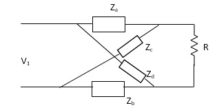 Diagram
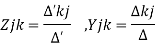
Where,
∆- nodded basis determinant
∆- Loop basis determinant
∆’kj , ∆ jk- cofactor
Voltage ration transfer function 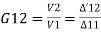
Current raw transfer function 
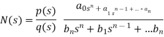
Pole -Zero plot of a Network Function-
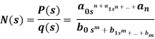
a, b- coefficient with are real and positive
Features of poles and zero of network function.
a) The network function is described by poles and zeros.
b) The zeros of the network exit for the complex frequencies where N(s)=0
c) The poles of the network exit for the complex frequencies where N(s)=o
d)The number of poles is equal to number of zeros considering types poles and zeros which at infinity.
e) when n>m, poles at infinity has degree(n-m)
f) When m>n, zeros at infinity with degree (m-n)
g) The time variation response of the network is determined through the poles.
h) The magnitude of response is determined by poles and zeros of the network function.
i) If q(s) =0, is the characteristics equation of N(S).
J) Capacitor is represented as (ʊ)=1/cs so, for
S = 0, It behaves open circuits
S= behaves as short circuit
k) for inductor z(s) = Ls so, for
s= o It behaves short circuit
s = It behaves as given circuits
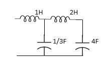
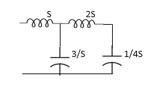
 Que) For the network shown, find driving point input impedance. Plot the pole zero pattern for each as well.
DIAGRAM
Solution - for fig 1) taking L.T we have

Diagram
Z11= 1+ 1 /S/3+1/25+1/1/4S
=1+ 1/ 5/3+1/6S
=1+ 18S/6S2+3
Z11=6S2+3+18S/ 6S2+3 =2S2+6S+2/2S2+1
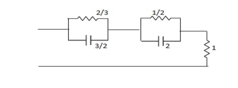
Zeros of equations are taking lt.of circuit b)
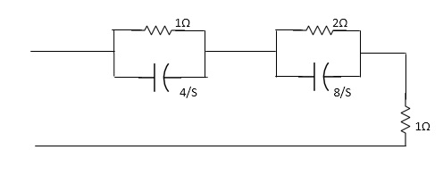
Diagram-
Z11= 1*4/5
1+4/5+2.8/3/2+8/5+1
=4/5+4 + 16/ 25+8+1
= 4/5+4+8/5+4+1
=s+12+4/ (5+4)
Z11= S+16/(S+4)
For zeros of system
s+16=0
s=-16
For poles of system
s+4=0
s=-4
Pole -zero plo is shown an
Restrictions of poles and zeros on driving point function
N(s) =p(s) =qosn+q, sn--------an/ q(s) bosn+b,sn-----------bn
1) All coefficient of p(s) and q(s) should be real and positive
2) poles and zeros must be conjugal whether imaginary or complex
3) Real part of poles and zeros must be negative or zero.
4) The degree of p(s) may differ either by zero or 1.
5) Lowest degree of p(s) and q(s) may differ at the most by one.
6) p(s) and q(s) cannot miss terms between highest and lowest degree unless all when or all odd terms are missing.
Q) Find whether the following network function represent the driving point function.
a) f(s)= (s+1)/(s2+1) b) f(s) = 3s2+2s+1/ss3+9s2+3s+2 c) f(s)=(s2+1)2/s2(s+3)
Solution
a) f(s)=s+1/s2+1
It represents the driving point function:
b) F(S)= 3S2+2S+1 / 5S3+9S2+3S+2
It represents the driving point function.
b) F(s)=3s2+2s+1/5s3+9s2+3s+2
It represents the driving point function
c) f(s) = (s2+1)2/s2(5+3)
It has representative zeros, hence not valid
(s2+1)2=0
s2=+-1
s2=+-j, +-j
v) Restriction as transfer function-
a) All coefficients of p(s) and q(s) should be real and positive for q(s)
b) The polis must be conjugal if imaginary or complex.
c) The real part of poles must be negative or new of zero than pole must be simple.
d)The degree of p(s) could be zero and it is independent of q(s). For example, f(s) 5/ (s3+3s+1)
e) q(s) cannot have missing terms between the highest and lowest degree unless all the even or all odd terms are missing
f) degree of q(s) >, p(s)
g) p(s) may have missing terms between the highest and lowest degree and its coefficients could be negative.
Time Domain Behaviour from pole -zero plot: -
To find the time domain behaviour we consider a simple RLC circuit. When the poles and zeros of I(s) can be represented in terms of undammed nautical frequency (wn)and damping ratio  . these can be represented as.
Wn = 1/ Lc and
  =R/2
=R/2 C/L
C/L
For RLC network the characteristics equation of any second differential equation.
s2+2 wns+wn2=0
s1s2=-2 wn+-
wn+- / 2
/ 2
=-2 wn+-
wn+- /2
/2
=-2 wn+-
wn+- /2
/2
=-2 wn+-2
wn+-2 / 2
/ 2
s1,s2 =- wn+-wn
So, depending an § poles can be represented in various ways
a)  >1
>1
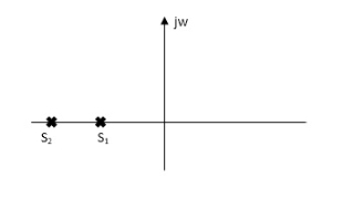 s1s2 = -
 wn+- wn
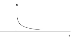

Diagram
As s1 s2 lies on negative real ax is .this corresponds to OVERDAMPED are have exponential decay from in the time domain.
b) 0< <1
<1
s1s2 = - wn+-∫wn
The roals are plotted below having both real and imaging part
Diagram
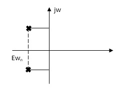
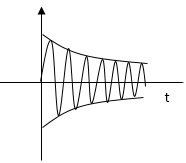
1)Roals plot 2) time response
As the roals have real and imaginary component as roals 0, this corresponds to UNDERDAMPED association. As initially oscillations exist but oscillations seen as t-
c)  =0
=0
s1s2 = - wn+- wn
s2+2 wns+w2n=0
For  =0
=0
s2+wn2=0
s=Ijwn
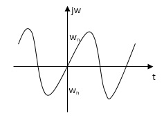 diagram
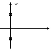
As the complex conjugal the as at t=0 and t= same so, this is the case of UNDAMPED associations.
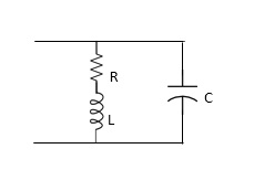
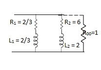
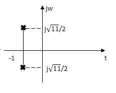 Q. For network below 1), pole - zero pattern is represented in fig 2) , find numerical value of R,L and c for z (0)=1?
Diagram=
Solution
Calculating z(s) by taking L.T of fig 1)
z(s) = (R+SL) *1/CS
(R+SL)+1/CS = R+SL / SRC+S2LC+1
Z(S)= S+R/L / C [S2+R/L S+1/LC]
Given z (0) =1
z (0) =R/L / C/LC =1
Z (0) =R=1
.: R=1
Polls are given as
S2+RS/L+1/LC=0
S=-R/2L +J
Zeros are given as
S+R / L=0
From pole zero plot value of pole location is at -1 so
-R / L = -1
-1/ L=-1
L=1H
Also, imaginary part of pole from plot is
 =
=
1/LC-(R/2L)2 =11/4
1/C-(1/2)2=11/4
1/C-1/4=11/4
1/C=11/4+1/4
1/C=12/4 =3
C=1/3 F
Hence, value of R=1 L=14 and c=1/3 f
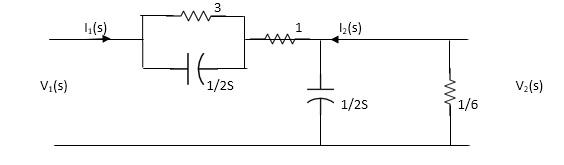
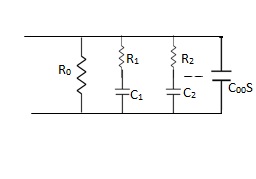
Q. FOR the following circuits, FIND G12(S) =v2/v1
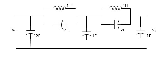
Solution= taking Laplace transform of above we have
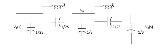
Applying KCL at node v0
V0-V1(S) / S*1/2S/(S+1/2S) +V0+V2(S)/ (S*1/2S)/(S+1/2S)+V0/1/S=0
For Porr 2) We have,
v2-v0/(s*1/2s)/(s+1/2s) +v2/1/s =0 ---------(ii)
(v2-v0) (2s2+1) / s +sv2=0
v2 [2s2+1/s+s] = v0(2s2+1)/ s
v0=v2(3s2+1) / (2s2+1) -----------(iii)
From (I) we have,
(v0-v1) /s (2s2+1) *sv0+(v0-v2)/5 (s2+1) =0
(2s2+1/5) v0-(2s2+1)/sv1+sv0+(2s2+1)/sv0-(s2+1)/s v2=0
(2s2+1)v1=(5s2+2)v0-(2s2+1)v2
Substitute value v0 from (iii) above
(2s2+1)v1 =[( 5s2+2)(3s2+1) /(2s2+1)-(2s2+1)]v2
(2s2+1)v1=(15s4+5s2+6s2+2-4s4+4s2) / (2s2+1 *v2
G12(s) = v2/v1 = (2s2+1) 2/11s4+15s2+1
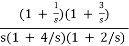
Q) Find the transfer function admittance ratio
Y12(s) = I2(S) / V1(S)
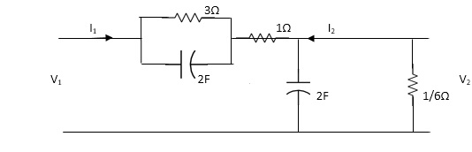
Solution = Taking Laplace transform of above figure
Applying KCL we get,
(V2-V1) / (3*1/2S) / (3+1/2S) * V2/ 1/2S+ V2/1/6 =0
(Y2-V1)(6S+1) / (6S+4) * (2S+6)V2V=0
BUT I2=-6V2
V2=-I2/6
We have ,
(6s+1) / (6s+4)*v2-(6s+1) / (6s+4)*v1 +(2s+6)v2=0
-[6s+1 / 6s+s+2s+6]I2 / 6 =V1(6S+1) / 6S+4
-[6S+1(2S+6)(6S+4)]I2= 6(6S+1)V1
-[(6S+1)*12S2+36S+8S+24] I2=6(6S+1)
I2 / V1 =-6(6S+1) / 12S2+50S+25
Y12(S) = I2(S) / V1(S) = -6(6S+1) / 12S2+50S+25
It gives relation between voltage and current for any network.
- Transfer function: -
Hurwitz – A Hurwitz polynomial has all its roots in the either left half plane or simple on imaginary axis conditions to be a Hurwitz polynomial.
(i) All its coefficients are real and positive.
(ii) Both its even and odd powers have roots on imaginary axis.
(iii) The continued fraction expansion of its odd to even or even to odd parts given positive coefficients.
(iv) If F(S) is equal to F1(S) and F2(S) then F(S) will be Hurwitz if both F1(S) and F2(S) are Hurwitz.
(v) The continued expansion of F(S) / F1(S) if gives a positive quotient then polynomial F(S) is Hurwitz.
Positive Real Function: A function is said to be positive Real if it has all the poles and zeros on the left half of S-plane and if the function has poles on imaginary axis then it should be simple.
Real Part of Function:
Re [ H(jw)] >=0 for all ‘w’
If a function F(S) is positive real then 1 / F(S) is also positive real. The highest degree and lowest degree of numerator and denominator of function may differ at the most by one. Sum of two positive real function is also positive real.
Properties of the Reactance Function (LC) :
(i) All poles and zeros are simple and lies on imaginary axis only.
(ii) It has a pole or zero at infinity and origin.
(iii) It is the quotient of even to odd or odd to even polynomials.
(iv) The residues at all poles are real and positive.
(v) The slope dF(s) / dw is always positive.
Properties of RC Impedance [ RL Admittance]:
(i) The poles and zeros are non-respective and lines on negative real axis.
(ii) The poles and zeros are alternate on real axis.
(iii) The lowest critical frequency is a pole.
(iv) The highest critical frequency is a zero.
(v) The residue at all its poles are real and positive
(vi) Z(0)>Z(∞)
w =0 w=∞
Properties of RL Impedance (RC Admittance)
(i) The poles and zeros are simple lies on negative real axis.
(ii) The poles and zeros are alternate on real axis.
(iii) Lowest critical frequency is zero.
(iv) Highest critical frequency is pole.
(v) Z(∞) >Z(0)
Q - For the given polynomials find whether they are Hurwitz polynomials or not.
a). F1(s) = s+ 3
b). F2(s) = s2 + 5
c). F3(s) = s2 + 5s + 6
d). F4(s) = s3 + 4s2 + 8s + 4
Sol:
a). F1(s) = s + 3
s = -3
Its Hurwitz polynomial
b). F2(s) = s2 + 5
s = Ij√5
Its Hurwitz polynomial
c). F3(s) = s2 + 5s + 6
s2 + 5s + 6
s2 + 2s + 3s + 2 x 3
(s + 3)(s + 2)
F3(s) =>s = -3, -2
It is Hurwitz polynomial.
d). F4(s) = s3 + 4s2 + 8s + 4
E(s) = 4s2 + 4 O(s) = s3 + 8s
4(s2 + 1) s (s2 + 8)
s = 1j s = 1j2√2
Its Hurwitz polynomial
Q. Find the range of K for which the polynomial 2s4 + s3 + ks2 + s+ 2 is Hurwitz?
Soln: s3 + s + 2) 2s4 + ks2 + 2 (2s
2s4 + 2s2
(k-2) s2 + 2) s3 + s + 2 (
s3 + 
------------------
s (1 –  ) + 2) (k-2) s2+ 2 (
------------------
k-2 > 0 (1 –  > 0
> 0
k > 2
1 >
k-2 > 2
k > 4
k > 2, k > 4
k > 4
Q .Find whether the given function F(s) = s + 4 / s2 + 2s + sis positive real or not?
Soln: By inspection check the function
(ii) Numerator and Denominator should both be Hurwitz
(iii) Real part of function must be positive for all values of W.
N(s) = s+ 4 D(s) = s2 + 2s + s
It is Hurwitz It is Hurwitz
Finding real part of function, s= jw.
F(jw) = 
=  +
+
=  x
x 
= 
Real part
= 
= 
For, w1 = 1, 2, …
For w > 3 function becomes negative. So not positive real.
Q .8s6 + 4s5 + 34s4 + 16s3 + 32s2 + 12s + 6. Find whether this is Hurwitz or not?
4s5 + 16s3 + 12s ) 8s6 + 34s4 + 32s2 + 6 ( 2s
8s6 + 32s4 + 24s2
---------------------------
2s4 + 8s2 + 6 ) 4s5 + 16s3 + 12s ( 2s
4s5 + 16s3 + 12s
-----------------------
* * *
This is the case of premature termination.
F(s) = F1(s).F2(s)
From above F1(s) = 2s4 + 8s2+ 6
F2(s) = 8s6 + 4s5 + 34s4 + 16s3 + 32s2 + 12s + 6
--------------------------------------------------------
2s4 + 8s2 + 6
2s4 + 8s2 + 6) 8s6 + 4s5 + 34s4 + 16s3 + 32s2 + 12s + 6 (4s2 + 2s + 1
8s6 + 32s4 + 24s2
---------------------------------------------------------
4s5 + 16s3 + 8s2 + 12s + 6 + 2s4
4s5 + 16s3 + 12s + 2s4
-------------------------------------------------
2s4 + 8s2 + 6
2s4 + 8s2 + 6
----------------------
* *
F1(s) = 2s4 + 8s2+ 6 – It is Hurwitz
F2(s) = 4s2 + 2s+ 1 – Has one root or RHS
F(s) is not Hurwitz as F2(s) is non Hurwitz.
Foster Realization
Foster (1) for
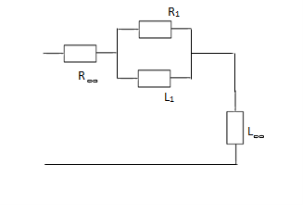 (a) RL Impedance: Lowest critical frequency is zero.
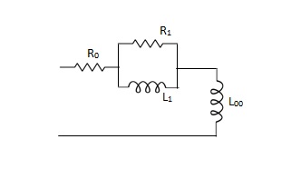
Z(s) =K0 +--------K∞s
R0 = K0, L∞ = K∞, R1 = K1, L1 = K1 / 
Ϭ1 = K1 / L1 = R1 / L1
K0 = Z(s) |S -> 0
K1 = Z(s)(s + Ϭ1) / s|S->1
K∞ = Z(s) / s|S -> ∞
(b) RC Impedance (RL Admittance)
The lowest critical frequency is a pole.
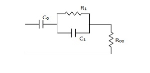
Z(s) = 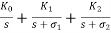 + --------K∞
K0 =  , R∞ = K∞, K1 =
  , R1 = K1
 = R1 / K1
K0 = SZ(s) |S->0
K1 = Z(s) (s + Ϭ1) | S = - 
K∞ = Z(s)|S->∞
Q. For the function Z(s) = s2 + 6s + 8 / s2 + 4s+ 3 is RL or RC.
Realise the above function.
Soln:
Z(s) = =
= 
All roots are -4, -2, (-1)->lowest, -3
Since lowest root is pole so its RC.
 1 = 1,
  2= 3
2= 3
Z(s) = 
K0 =  |S->0 = 0
K∞ =  S->∞
S->∞
K∞ = 1 => R∞ =1
K1 = 3/2 => R1 = 2/3 => C1 = 2/3
K2 = 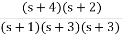 |S = -3
K2 = 1 / 2 => C2 = 2, R2 = 1/2
(c) LC Impedance (foster I)
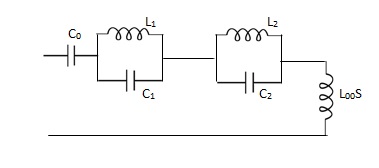
Z(S) = 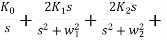 --- + K∞S
K0 = 1 / C0,  = 1 /
= 1 / 
 = 1 / 2
 , K∞ = L∞
 = 2
= 2 /
/ 
K0 = SZ(s) | s->0
 = Z(s)(s+
  1) | s = -
  1
1
 = Z(s)(s+
  2) | s = -
  2
2
Foster form II
 (a) RL – admittance :-
Y(s) = 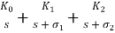 + --- K∞
K0 = SY(s) |S->0
K1 = Y(s) (s+  ) |S = -
K∞ = Y(s)|S -> ∞
L0 = 1 / K0, R∞ = 1 / K∞, Ϭ1 = R1 / L1
L1 = 1 / K1,  = 1 / R1K1
Q .Realise using foster form (2), Y(s) = s2 + 6s + 8 / s2 + 4s+ 3
Soln: Above function is RL admittance as lowest frequency is pole.
Y(S) = 
K0 =  |s->0 = 0, L0 = ∞
K1 = 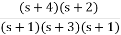 |s = -1
K1 = 3 / 2
L1 = 2 / 3, R1 = 2 / 3 ( / K1)
/ K1)
K2 = (s+4) (s+2) / (s+1) (s+3) (s+3) |S = -3
= 1 / 2, L2 = 2, R2 =  / K2 = 3 / ½ = 6
 K∞= (s+4) (s+2) / (s+1) (s+3) |s -> ∞
= (1 + 4 / s) (1 + 2 / s) / (1 + 1 / s) (1 + 3 / s) |S -> ∞
K∞ = 1, R∞ = 1 / K∞ = 1
(b) RC Foster (2) Admittance
Y(s) = K0 + K1s/ s +  + K2s/ s +
  + --- +K∞s
K0 = Y(s)|S->0
K∞ = Y(s) / s|S->∞
K1 = Y(s) / s (s +  )|S = -
K0 = 1 / R0, C∞ = k∞, K1 = 1 / R1
C1 = K1 / 
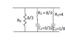
Q – Realise the following function Y(s) = s2 + 4s + 3 / s2 + 6s+ 8
Soln: Lowest critical frequency is zero.  = +4,
= +4,  = +2
= +2
Y(s) =
K0 = 3 / 8, R0 = 8 / 3
K∞ =  |S->∞
|S->∞
=  / S->∞
K∞ = 0, C∞ = 0
K1 =  |S = -4
K1 = 3/8, R1 = 8/3
 C1 = K1/
 1 = 3/8 x ¼ = 3/32
K2 = (s+1) (s+3) / s(s+4) (s+2) |S = -2 = 1/4
K2 = 1/4, R2 = 4
C2 = K2/  2 = 1/8
( c ) LC Admittance Foster form (2)
Y(s) = 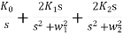 + ---- + k∞s
L0 = 1/K0, C∞ = K∞, L1 = 1/2K1, W12 = 1/L1C1
C1 = 2K1 / W12
Reference
- Engineering Circuit Analysis”, by W H Hayt, TMH Eighth Edition
- “Network analysis and synthesis”, by F F Kuo, John Weily and Sons, 2nd Edition.
- “Circuit Theory”, by S Salivahanan, Vikas Publishing House 1st Edition, 2014
- “Network analysis”, by M. E. Van Valkenburg, PHI, 2000
- “Networks and Systems”, by D. R. Choudhary, New Age International, 1999
- Electric Circuit”, Bell Oxford Publications, 7th Edition.


