Unit - 3
Introduction to Mobile Communication
The cellular network in also called as PCS which stands for Personal Communication System. The objective of PCS is to enable communication with a person at any time, at any place & in any form. It also manages their individual call services according to their service by providing unlimited reachability & accessibility. Sprint was the first company to set up a PCS network, which was a GSM-1900 network in the Baltimore-Washington metropolitan area in the USA. PCS promises to provide a wide range of locations and equipment-independent services to a large number of users. According to the definition given by the US Federal Communications Commission (FCC), PCS is the system by which every user can exchange information with everyone, at anytime, in any place, through any type of services, using a single personal telecommunication number (PTN). Key factors of PCS are:
1. Reachability with respect to Location (Home, office, in public, in transit)
1. Accessibility with respect to Device (Cellular phone, wired phone, fax etc.)
2. Management of Service.
- The design objective of early mobile radio systems was to achieve a large coverage area using a single, high powered transmitter with an antenna mounted on a tall tower
- The cellular concept is a system-level idea which calls for replacing a single, high power transmitter (large cell) with many low power transmitter (small cells) each providing a coverage to only a small portion of the service area While it might seem natural to choose a circle to represent the coverage of a BS, adjacent circles cannot be overlaid upon a map without leaving gaps or creating overlapping regions Thus when considering geometric shapes which cover an entire region without overlap and with equal area, there are three sensible choices – a square, an equilateral triangle and a hexagon
- The actual radio coverage of a cell is known as footprint and is determined from field measurements or propagation prediction models
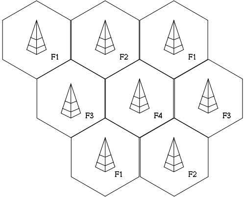
Fig 1. The Cellular Model
- Why hexagon for theoretical coverage?
- For a given distance between the centre of a polygon and its farthest perimeter points, the hexagon has the largest area of the three
- Thus by using hexagon geometry, the fewest number of cells can cover a geographic region, and hexagon closely approximates a circular radiation pattern which would occur for an omnidirectional BS antenna and free space propagation
- When using hexagons to model a coverage areas, BS transmitters are depicted as either being in the centre of the cell (centre-excited cells) or on the three of the six cell vertices (edge-excited cells)
- Normally omnidirectional antennas are used in centre-excited cells and directional antennas are used in corner-excited cells
Why cellular systems:
- Solves the problem of spectral congestion
- Reuse of radio channel in different cells
- Enable a fixed number of channels to serve an arbitrarily large number of users by reusing the channel throughout the coverage region
The cellular system is replaced by large number of base stations (BS) which are hexagonal cells. They cover certain range of areas.
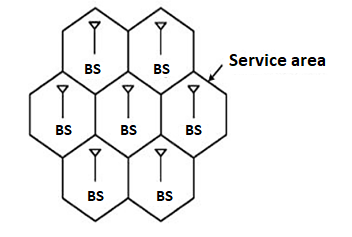
Fig 2. Cellular Structure
For having the communication in cellular structure, we need Mobile station (MS). In these types of structures, the MS communicates with the BS of cell. This is the location of MS in a BS cell. This BS acts as a gateway. For establishing connections, the MS needs to be in the range of the system. The figure below shows the same.
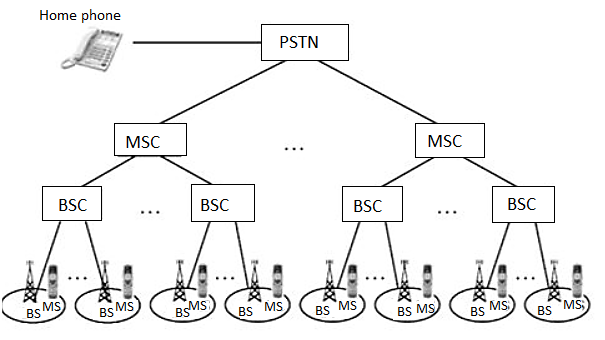
Fig 3. Cellular system infrastructure
Each base station controller (BSC) consists of MS and a BS. These BSC are then connected to the Mobile switching Centre (MSC). These MSC are then connected to a Public Switch Telephone Network (PSTN) and the Asynchronous Transfer Mode (ATM).
A base station consists of several base transceiver stations (BTS) and a BSC. The antenna and tower are the parts of BTS. The BTS system consists of towers and antennas.
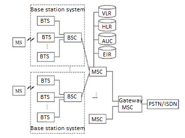
Fig 4. Generic block diagram of cell structure
The Home location register (HLR) is located at MSC. The MS is registered there only in the home location. The visitor location register (VLR) and HLR support mobility and helps to use one number i.e same number anywhere in world. The VLR has information about all MS.
The authentication and encryption are provided by Authentication centre (AUC). The database which provides identity and information about the mobile is equipment identity register (EIR).
Whenever there is a call it is directed to HLR where home MS is registered. This is then forwarded to VLR of MSC where MS is located currently.
Key takeaway
- Each base station controller (BSC) consists of MS and a BS
- These MSC are then connected to a Public Switch Telephone Network (PSTN) and the Asynchronous Transfer Mode (ATM).
- The authentication and encryption are provided by Authentication center. (AUC).
Architecture consists of two parts Radio Network PCS users carry mobile stations (MS) to communicate with a BS in a PCS n/w. MS is also referred to as handset or mobile phone. The radio coverage of a base station is called cell. In GSM n/w each cell is controlled by BSC which are connected to MS through BS. The BSCs are connected to MSC by landlines.
Wireline Transport Network
An MSC is a telephone exchange configured specially for mobile applications. It interfaces the MSC (via BS) with PSTN. MSCs are also connected with mobility database to track the location of MS and roaming management. The databases are HLR & VLR. HLR contains the authentication information like IMSI (International Mobile Subscriber Identity), identification information like name, address of the subscriber, billing information like prepaid or post-paid, operator selection, denial of service to a subscriber etc. VLR gives information about the location area of the subscriber while on roaming and power off status of the handset.
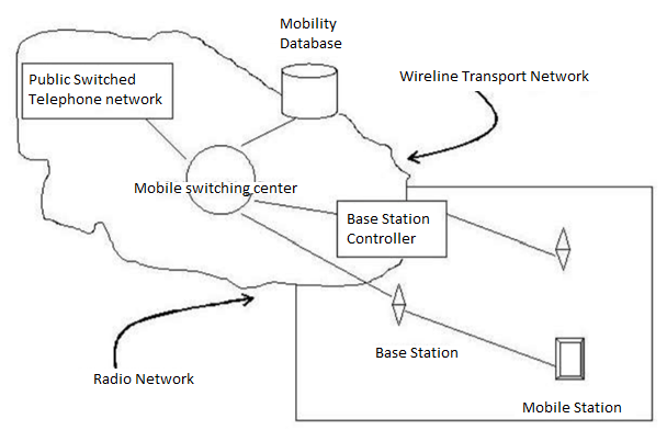
Fig 5. PCS Network Architecture
Key takeaway
Key factors of PCS are:
1. Reachability with respect to Location (Home, office, in public, in transit)
1. Accessibility with respect to Device (Cellular phone, wired phone, fax etc.)
2. Management of Service.
To calculate the predicted number of calls per hour per cell Q in each cell, the following parameters are required
- The size of the cell
- The traffic conditions in the cell
Maximum number of frequency channels per cell. The maximum number of frequency channels per cell N is closely related to an average calling time in the system. The standard user’s calling habits may change as a result of the charging rate of the system and the general income profile of the users If an average calling time T is 1.76 min and the maximum calls per hour per cell is Qi, then the offered load can be derived as
A = Qi*T/60 (Erlangs)
If the blocking probability is given, then it is easy to find the required number of radios in each cell. If a large area is covered by 28 cells, Kt = 28; the total number of customers in the system increases. Therefore, we may assume that the number of subscribers per cell Mi is somehow related to the percentage of car phones used in the busy hours and the number of calls per hour per cell Qi as
Mi=f (Qi, n)
Where the value Qi is a function of the blocking probability B, the average calling time T, and the number of channels N.
Qi= f (B, T, N)
- Each cellular BS is allocated a group of radio channels to be used within a
Small geographic area called cell
- BS in adjacent cells are assigned channel groups which contain completely
Different channels than neighbouring cells
- By limiting the coverage area to within the boundaries of a cell, the same
Groups of channels may be used to cover different cells that are separated from one another by distances large enough to keep the interference levels within tolerable limits
- The design process of selecting and allocating channel groups for all of the
Cellular BSs is called frequency reuse or frequency planning

Fig. 6 Cellular Frequency reuse concept
- Cells with the same letter use the same set of frequencies.
- A cell cluster is outlined in bold.
- In this Example, the cluster size is N equal to 7 and frequency reuse factor is 1/N=1/7
The concept of Cell Splitting is quite self explanatory by its name itself. Cell splitting means to split up cells into smaller cells. The process of cell splitting is used to expand the capacity (number of channels) of a mobile communication system. As a network grows, a quite large number of mobile users in an area come into picture. Consider the following scenario.
There are 100 people in a specific area. All of them owns a mobile phone (MS) and are quite comfortable to communicate with each other. So, a provision for all of them to mutually communicate must be made. As there are only 100 users, a single base station (BS) is built in the middle of the area and all these users’ MS are connected to it. All these 100 users now come under the coverage area of a single base station. This coverage area is called a cell. This is shown in Figure.

Fig. 7 A single BS for 100 MS users.
But now, as time passed by, the number of mobile users in the same area increased from 100 to 700. Now if the same BS has to connect to these 700 users’ MS, obviously the BS will be overloaded. A single BS, which served for 100 users is forced to serve for 700 users, which is impractical. To reduce the load of this BS, we can use cell splitting. That is, we will divide the above single cell into 7 separate adjacent cells, each having its own BS. This is shown in Fig 2-2.
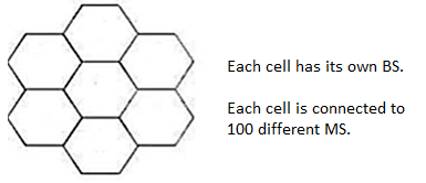
Fig. 8 Single cell split up into 7 cells.
Now, let us look into the big picture. Until now, we have discussed about cell splitting in a small area. Now, we use this same concept to deal with large networks. In a large network, it is not necessary to split up all the cells in all the clusters. Certain BSes can handle the traffic well if their cells (coverage areas) are split up. Only those cells must be ideal for cell splitting. Fig 2-3 shows network architecture with a few number of cells split up into smaller cells, without affecting the other cells in the network.
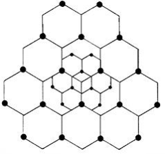
Fig. 9 Cell Splitting
The concept of cell splitting can further be applied to the split cells as well. That is, the split up cells can further be split into a number of smaller cells to improve the efficiency of the BS even more. Fig 2-4 shows a hierarchy of cell splitting.
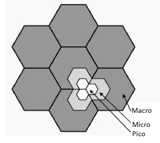
Fig. 10 Cell Splitting of Split up cells.
Here, the master cells which have been split up into smaller cells are known as macro cells. The split up cells are known as micro cells. The innermost cells, split up by splitting the micro cells are known as pico cells.
Cell Sectoring
In cellular telephone system, co-channel interference can be decreased by replacing a single omnidirectional antenna with several directional antennas, each radiating within a smaller area.
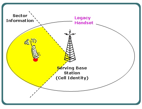
Fig. 11 Cell Sectoring
Another way of improving the channel capacity of a cellular system is to decrease the D/R ratio while keeping the same cell radius. Improvement in the capacity can be accomplished by reducing the number of cells in a cluster, hence increasing the frequency reuse. To achieve this, the relative interference must be minimized without decreasing the transmit power.
For minimizing co-channel interference in a cellular network, a single Omni-directional antenna is replaced with multiple directional antennas, with each transmitting within a smaller region. These smaller regions are called sectors and minimizing co-channel interference while improving the capacity of a system by using multiple directional antennas is called sectoring. The amount up to which co-channel interference is minimized depends on the amount of sectoring used. A cell is generally divided either into three 120 degree or six 60 degree sectors. In the three-sector arrangement, three antennas are generally located in each sector with one transmit and two receive antennas.
When sectoring technique is used in cellular systems, the channels used in a particular sector are actually broken down into sectored groups, which are only used inside a particular sector. With 7-cell reuse pattern and 120 degree sectors, the number of interfering cells in the neighboring tier is brought down from six to two.
Cell sectoring also improves the signal-to-interference ratio, thereby increasing the capacity of a cellular system. This method of cell sectoring is very efficient, because it utilized the existing system structures.
Cell sectoring also minimized the co-channel interference, with the use
Of directional antennas, a particular cell will get interference and transmit only a fraction of the available co-channel cells.
Processing handoffs is an important task in any cellular radio system. Handoffs must be performed successfully and as infrequently as possible and be imperceptible to the user. In order to meet these requirements, system designer must specify an optimum signal at which to initiate a handoff.
This margin is given by cannot be too large or too small. If is large unnecessary handoffs which burden the MSC may occur and if is too small, there may be may be insufficient time to complete a handoff before a call is lost to meet these conflicting requirements. Figure is given which explains the different steps of handoff required to meet.
Following figure demonstrates the case where a handoff is not made and the signal drops below the minimum acceptable level to keep the channel active. The systems. Excessive delay may occur during high traffic conditions or due to no channels are available on any of the nearby base stations.
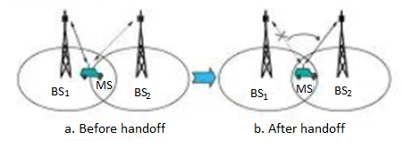
In deciding when to handoff, it is important to ensure that the drop in the measured signal is not due to momentary fading and the mobile is actually moving away from the serving base station. But when there is a drop in the measured signal level due to momentary fading and not due to the actual moving mobile away from the base station, that is situation if the handoff of a call takes place then such handoffs must be prevented by ensuring that the base station monitors the signal level for a certain period of time before the handoff is initiated.
When a mobile moves into a different cell while a conversation is in progress, the MSC automatically transfers the call to a new channel belonging to the new base station. This handoff operation not only involves identifying a new base station, but also requires that the voice and control signals be allocated to channels associated with the new base station.
Three strategies have been proposed
- In mobile-controlled handoff(MCHO)
- In network-controlled handoff(NCHO)
- In mobile-assisted handoff(MAHO)
- In mobile-controlled handoff(MCHO)
The MS continuously monitors the signal of surrounding BSs and initiate the handoff process when some handoff criteria are met. MCHO is used in DECT
(Digital Enhanced Cordless Telecommunications)
2. In network-controlled handoff (NCHO)
The surroundings BSs measure the signal from the MS, 7 the network initiates the handoff process when some handoff criteria are met.
3. In mobile-assisted handoff (MAHO)
The network ask the MS to measure the signal from the surrounding BSs. The network makes the handoff decision based on report from the MS. MAHO is used in GSM & IS-95 CDMA
Inter-BS Handoff
In inter-BS handoff, the new & old BSs are connected to same MSC. Assume that the need for handoff is detected by the MS therefor the following actions are to be considered.
- The MS temporarily suspend conversation & initiates the handoff procedure by signalling on free channel in new BS. Then it resumes the conversation on the old BS. As in fig below.
2. Upon receipt of the signal, the MCS transfer the encryption information to the selected idle channel of the new BS & set up the new conversation path to the MS through that channel.as in fig below
3. After the MS has been transferred to the new BS, it signals the network and resume conversation using the new channel. As in fig below
4. Upon receipt of the handoff completion signal the network removes the bridge from the path and release resources associated with the old channel as in fig below.
This handoff procedure is used with mobile controlled handoff strategy. For network controlled handoff signalling messages are exchanged between the MS & old BS through the falling link. The whole process is completed as quickly as possible to ensure that new link
Interference & system capacity
In telecommunications, interference is anything which modifies, or disrupts a signal as it travels along a channel between a source and a receiver. The term typically refers to the addition of unwanted signals to a useful signal. For example
- Electromagnetic interference (EMI)
- Co-channel interference (CCI), also known as crosstalk
- Adjacent-channel interference (ACI)
- Inter symbol interference (ISI)
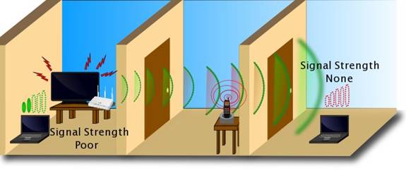
Fig 12. Interference Systems
Co-channel interference
Co-channel interference or CCI is crosstalk from two different radio transmitters using the same frequency.
Co-channel interference occurs between two access points (APs) that are on the same frequency channel. The reason that you should care is that co-channel interference can severely affect the performance of your wireless LAN (WLAN).
Co-channel interference is more problematic when you deploy your WLAN to support voice or RFID location tagging. These types of scenarios require a denser deployment of APs. Denser deployments mean that your APs are closer together. And that creates a greater potential of two devices that transmit on the same frequency channel will be close enough to cause significant interference to each other's signals.
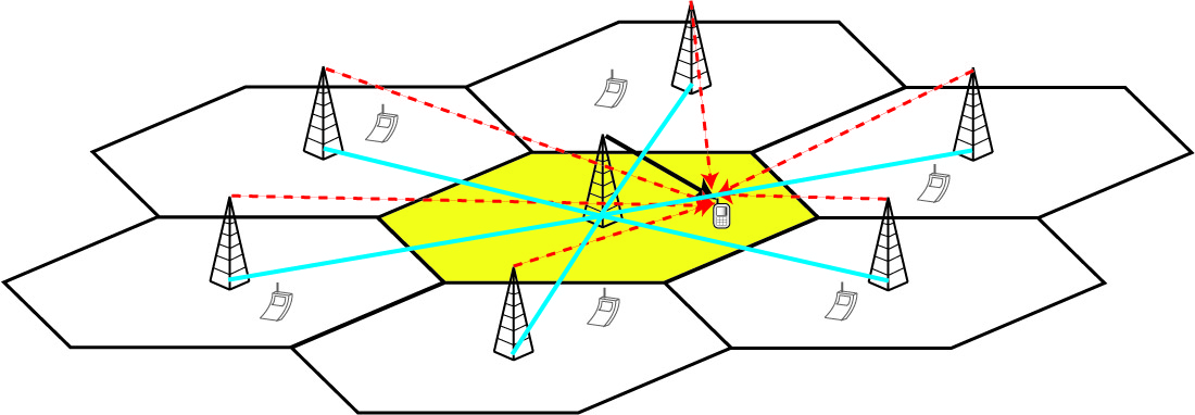
Fig.13 Co-channel interference
There can be several causes of co-channel radio interference; four examples are listed here.
- Cellular Mobile Networks:
In cellular mobile communication (GSM & LTE Systems, for instance), frequency spectrum is a precious resource which is divided into non-overlapping spectrum bands which are assigned to different cells (In cellular communications, a cell refers to the hexagonal/circular area around the base station antenna). However, after certain geographical distance, the frequency bands are re-used, i.e. the same spectrum bands are reassigned to other distant cells. The co-channel interference arises in the cellular mobile networks owing to this phenomenon of Frequency reuse. Thus, besides the intended signal from within the cell, signals at the same frequencies (co-channel signals) arrive at the receiver from the undesired transmitters located (far away) in some other cells and lead to deterioration in receiver performance.
- Adverse weather conditions:
During periods of uniquely high-pressure weather, VHF signals which would normally exit through the atmosphere can instead be reflected by the troposphere. This tropospheric ducting will cause the signal to travel much further than intended; often causing interference to local transmitters in the areas affected by the increased range of the distant transmitter.
- Daytime vs Nighttime: In the Medium frequency portion of the radio spectrum where most AM broadcasting is allocated, signals propagate full-time via groundwave and, at night time, via sky wave as well. This means that during the night time hours, co-channel interference exists on many AM radio frequencies due to the medium waves reflecting off the ionosphere and being bounced back down to earth. In the United States, Canada, Mexico, and the Bahamas, there are international agreements on certain frequencies which allocate "clear-channel" broadcasting for certain stations to either have their respective frequencies to themselves at night, or to share their respective frequencies with other stations located over hundreds or even thousands of miles away. On other frequencies, there are "Regional Channels" where most stations on these frequencies either reduce power or change to a directional antenna system at night time to help reduce co-channel interference to each other's signals. In the United States, there are six "Local Channel" frequencies, also known as "grave yarders" where nearly every station on those frequencies has the same power and antenna pattern both day and night and, as a result of sky wave propagation, there is normally massive co-channel interference in rural areas on these frequencies, often making it difficult, if not impossible, to understand what's being said on the nearest local station on the respective channel, or the other distant stations which are bouncing on the same channel, during the night time hours.
Adjacent channel Interference
Adjacent-channel interference (ACI) is interference caused by extraneous power from a signal in an adjacent channel.
Adjacent channel interference (ACI) is interference between links that communicate geographically close to each other using neigh boring frequency bands. For instance, several network operators may deploy their own networks in the same area and operate on frequency bands that are close to each other. Hence, ACI needs to be taken into account in the system specifications so that it will not hamper the system performance.
Adjacent channel interference: interference from adjacent in frequency to the desired signal.
– Imperfect receiver filters allow nearby frequencies to leak into the passband
– Performance degrade seriously due to near-far effect.
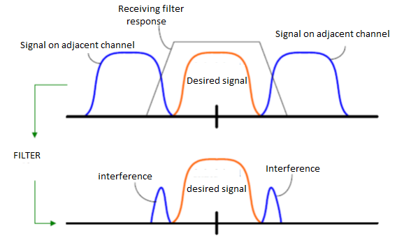
Fig 14. Adjacent channel
Adjacent channel interference can be minimized through careful filtering and channel assignment.
• Keep the frequency separation between each channel in a given cell as large as possible
• A channel separation greater than six is needed to bring the adjacent channel interference to an acceptable level.
Channel planning for wireless system
A successful wireless network deployment is completely dependent on the Wireless planning process
Many wireless network deployments can fail to deliver reliability, capacity and performance due to poor planning and network design, a bad site survey or network implementation.
• Judiciously assigning the appropriate radio channels to each base station
Is an important process
• That is much more difficult in practice than in theory
• For determining the appropriate frequency reuse ratio (or) cluster size & the appropriate separation between adjacent co- channel cells
• Generally the available mobile radio spectrum is divided into channels.
• Channels are part of an air interface standard that is used throughout a country or continent
• There are two type of channel required for wireless communication
• Voice Channel
• Control channel
• Voice channel are 95% Dedicated for carrying revenue generating traffic
• In practical systems the air interface standard ensures a distinction between voice channel & control channel.
• Control channels are vital for initiating, requesting, paging
• Since control channels are vital in successful launch of any call , the frequency re use strategy applied to control channels is different and generally more conservative
• Typically, Control channels are able to handle a great deal of data such that only one control channel is needed within a cell
• Control channels are generally not allowed to be used as voice channel
&voice channels are generally not allowed to be used as Control channel
Power Control for Reducing Interference
Ensure each mobile transmits the smallest power necessary to maintain a good quality link on the reverse channel
– long battery life
– increase SIR
– solve the near-far problem
Hand Off
When a mobile user is engaged in conversation, the MS is connected to BS via radio link. If the user moves to the coverage area of another BS, the radio link to old BS is disconnected and radio link to new BS is established to continue conversation. This process is called automatic link transfer or handoff. Depending on the mobility of MS, the handoff is divided into two categories:
Inter-BS Handoff/ Inter Cell Handoff: Here MS usually moves from one BS to another BS under one MSC. Action taken for communication:
1. The MS momentarily suspends conversation & initiates the hand-off procedure by picking a channel in new BS. Then is resumes the conversation in old BS.
2. When MSC receives that signal, he transfers the information to the new BS & sets up new conversation path to MS through that channel.
3. After MS has been transferred to new BS, it starts the conversation channel with new BS & then MSC disconnect the link with old BS.
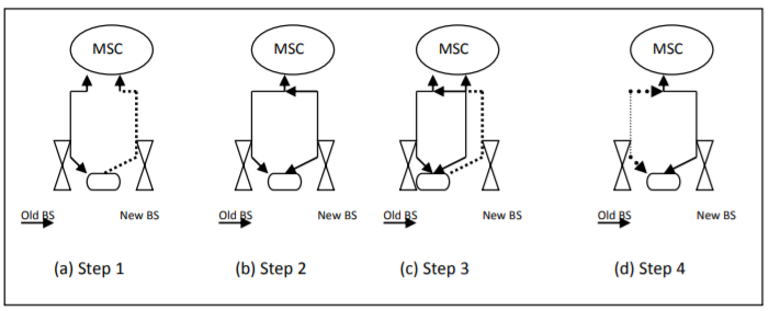
Fig 15. Inter-BS link Transfer
Inter-System Handoff/Inter-MSC Handoff
MS moves from one BS to another connected to two different MSCs. Action taken for communication:
1. MSC1 requests MSC2 to perform handoff measurement on the call in progress.
2. MSC2 then selects a BS by interrogating the signal quality and sends the information to MSC1.
3. Then MSC1 asks MSC2 to setup a voice channel.
4. Assuming that a voice channel is available in BS2.MSC2 instructs MSC1 to start radio link transfer. 5. MSC1 sends the MS a handoff order. Now MS can access BS2 of MSC2.MSC2 informs MSC1 that handoff is successful.MSC1 then connects call path to MSC2.
6. In the intersystem handoff process, anchor MSC is always in call path before & after handoff.
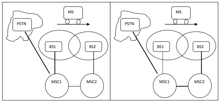
Fig 16. Inter system handoff
Path Minimization- When MS moves to MSC3, MSC2 may be removed from the call path. The link between MSC1 and MSC2 is disconnected and MS connects to MSC3 directly. This process is called path minimization.
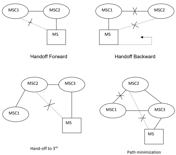
ROAMING:
When a mobile user moves from one PCS system to another, then the system should be informed of the current location of the user. Otherwise it is impossible to deliver services. Two basic operations are performed under roaming management.
1. Registration (location update): Where MS informs the system its current location.
2. Location tracking: Process during which a system locates MS. Location tracking is required when n/w attempts to deliver call to a mobile user. The roaming management follows a two level strategy where two tier systems of home and visited databases are used. When a user subscribes to the services of a network, a record is created in the system’s database called HLR. This is referred to as home system of the mobile user. HLR is a n/w database, where MS's identity, profile, current location & validation period is stored. When the mobile user visits a new network other than home system, a temporary record for the mobile user is created in the VLR of visited system. VLR temporarily stores information for visiting subscribers so that corresponding MSC can provide service.
Registration Procedure includes following steps:
1. When mobile user enters into new PCS n/w, it must register in VLR of new system.
2. The new VLR informs mobile user's HLR regarding the current location & address of user. The HLR sends an acknowledgement which includes MS's profile, to the new VLR.
3. New VLR informs MS about successful registration.
4. HLR sends a deregistration message to cancel the location record of MS in old VLR. The old VLR acknowledges the deregistration.
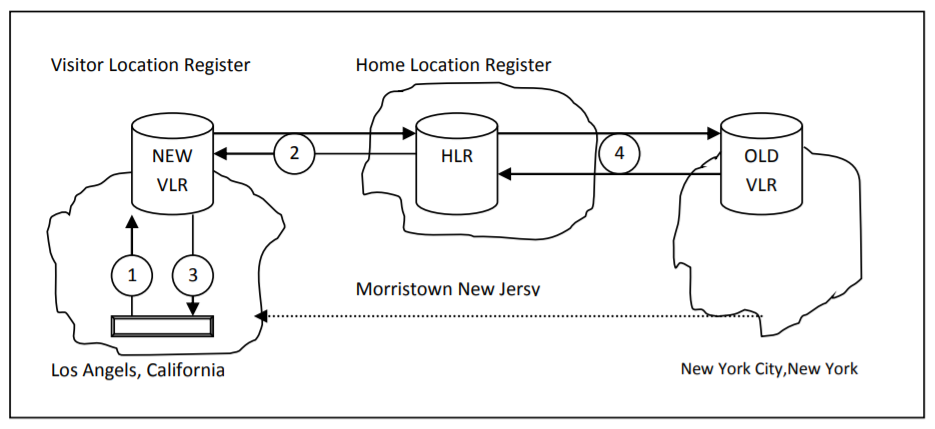
Fig 17. MS Registration Process
To originate a call, MS first contacts with MSC in the new PCS n/w. The call request is forwarded to VLR for approval. If it is approved, MSC sets up the call to the user following the standard PSTN procedures.
1. If a wireline phone attempts to call a mobile subscriber, the call is forwarded to switch called the originating switch in PSTN. The switch masses a query to HLR to find current VLR of MS. The HLR queries the VLR in which MS resides to get a communicable address.
2. The VLR returns the address to switch through HLR.
3. Based on address, a communication link is established between MS through visited MSC.
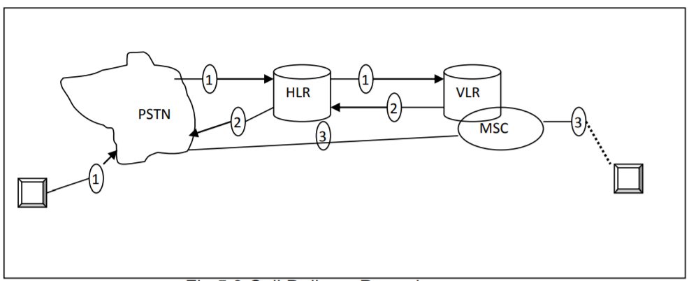
Fig 18. Call Delivery Procedure
Key takeaway
Mobility management function handles the function that arises due to mobility of the subscriber. Main objective of MM is location tracking & call set up. There are two aspects of mobility in a PCS n/w.
References:
1. Cristopher Cox, “An Introduction to LTE: LTE, LTE-Advanced, SAE, VoLTE and 4G Mobile Communications”, Wiley, 2nd Edition.
2. E. Dahlman, J. Skold, and S. Parkvall, “4G, LTE-Advanced Pro and The Road to 5G”, Academic Press, 3rd Edition.
3. B. P. Lathi, “Modern Digital and Analog Communications Systems”. Oxford university press, 2015, 4th Edition.
4. Obaidat, P. Nicopolitids, “Modeling and simulation of computer networks and systems: Methodologies and applications” Elsevier, 1st Edition.