Unit - 4
Wireless System Planning
Link budgets are, as the name implies, an accounting of the gains and losses that occur in a radio channel between a transmitter and receiver. We’ve talked about S/I – you need an acceptable signal to interference ratio. In addition, you need an acceptable signal to noise, or S/N, ratio. (a.k.a. SNR, C/N, or Pr/PN ratio, where C stands for carrier power, the same thing we’ve been calling Pr, and N or PN stands for noise power. Since we’ve already used N in our notation for the cellular reuse factor, we denote noise power as PN instead.) Noise power is due to thermal noise.
Also, there is a concept of path balance, that is, having connectivity in only one direction doesn’t help in a cellular system. So using too much power in either BS or mobile to make the maximum path length longer in one direction is wasteful. As we’ve said, this is accounting. We need to keep track of each loss and each gain that is experienced. Also, to find the noise power PN , we need to know the characteristics of the receiver.
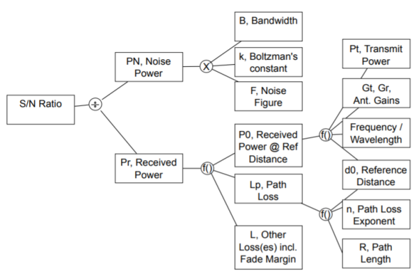
Fig 1 Relationship among link budget variables.
Link Budget Procedure
A universal link budget for received power is:
Pr(dBW)= Pt(dBW) + 
A universal link budget for S/N is:
S/N = Pr(dBW) − PN (dBW) = Pt(dBW) +  + PN(dBW)
- There’s no particular reason I chose dBW instead of dBm for Pr and PN. But they must be the same, otherwise you’ll have a 30 dB error!
- If using EIRP transmit power, it includes Pt(dBW) + Gt(dB), so don’t double count Gt by also including it in the dB Gains sum.
- The dB noise figure F (dB) is either included in PN (dBW) or in the dB losses, not both!
- Gains are typically only the antenna gains, compared to isotropic antennas.
- There are also coding, a.k.a. Processing, gains, achieved by using channel coding to reduce the errors caused by the channels. DS-SS (e.g., CDMA) is a type of modulation which has a processing gain. These might be subtracted from the required S/N ratio, or added to the gains. Do one, but not both.
- Losses include large scale path loss, or reflection losses (and diffraction, scattering, or shadowing losses, if you know these specifically), losses due to imperfect matching in the transmitter or receiver antenna, any known small scale fading loss or “margin” (what an engineer decides needs to be included in case the fading is especially bad), etc.
- Sometimes the receiver sensitivity is given (for example on a RFIC spec sheet). This is the PN (dB) plus the required S/N(dB).
Thermal noise
The thermal noise power in the receiver is PN, and is given as PN = F kT0B, where
- k is Boltzmann’s constant, k = 1.38 × 10⁻²³J/K. The units are J/K (Joules/Kelvin) or W·s/K (1 Joule = 1 Watt × second).
- T0 is the ambient temperature, typically taken to be 290-300 K. If not given, use 294 K, which is 70 degrees Fahrenheit.
- B is the bandwidth, in Hz (equivalently, 1/s).
- F is the (unitless) noise figure, which quantifies the gain to the noise produced in the receiver. The noise figure F ≥ 1.
In dB terms, PN (dBW) = F(dB) + k(dBWs/K) + T0(dBK) + B(dBHz) where k(dBWs/K) = 10 log10 1.38 × 10⁻²³J/K = −228.6 dBWs/K. We can also find F from what is called the equivalent temperature Te. This is sometimes given instead of the noise figure directly
F = 1 + Te/T0
Example
Consider a system with operating bandwidth of 500 MHz, center frequency of 60 GHz, and transmitter-receiver separation of 10 m. The Effective Isotropic Radiated Power is 40 dBm, implementation loss is 6.3 dB, and the receiver noise figure is 10 dB. The modulation scheme employed is BPSK, and the minimum SNR required at the receiver is 9.6 dB. Assume, k = 1.38 × 10⁻²³J/K and temperature, T = 290 K. The link margin of receiver will be?
Link Margin = (SNR)r − (SNR)rmin = 22.7 dB − 9.6 dB = 13.1 dB or
Alternatively Link Margin = Pr − Sr = −48 dBm − (−61.1) dBm = 13.1 dB
Consider the uplink of a GSM system, given GSM requires an S/N of 11 dB. Assume a maximum mobile transmit power of 1.0 W (30 dBm), 0 dBd antenna gain at the mobile, and 12 dBd gain at the BS. Assume path loss given by the urban area Hata model, with fc = 850 MHz, BS antenna height of 30 meters, mobile height of 1 meter. Assume F = 3 dB and that the system is noise-limited. What is the maximum range of the link?
S/N required is 11 dB.
PN = F kT0B = 2(1.38 × 10⁻²³J/K) (294K) (200 × 103Hz) = 1.62 × 10−15 = −147.9(dBW).
Pt = 0 dBW.
Gains: include 0 dBd and 12 dBd (or 2.15 dBi and 14.15 dBi) for a total of 16.3 dB gains.
Losses: Path loss is via urban area Hata, for d in km
L(dB) = 69.55 + 26.16 log10(850) − 13.82 log10(30) + [44.9 − 6.55 log10(30)] log10 d = 125.8 + 35.22 log10 d
So,
11(dB) = 0(dBW) + 16.3(dB) − (125.8 + 35.22 log10 d) + 147.9(dBW)
d = 1027.4/35.22 = 6.0(km)
Note 1 km = 0.62 miles, so this is 3.7 miles.
Determine the transmit power required for a 500 Mbps QPSK modulated bit stream if the minimum SNR desired at the receiver is 12 dB. Assume receiver noise figure of 10 dB, carrier frequency of 2.4 GHz, transmission distance of 100 m, and a wireless channel with a fading margin of 8 dB. Assume, k = 1.38 × 10⁻²³J/K and temperature, T = 290 K. The required operating bandwidth will be?
According to given data Rb = 500Mbps
For QPSK modulation,
Required Bandwidth will be B= Rb/2 = 500x106 /2 = 250MHz
Consider a system with operating bandwidth of 500 MHz, center frequency of 60 GHz, and transmitter-receiver separation of 10 m. The Effective Isotropic Radiated Power is 40 dBm, implementation loss is 6.3 dB, and the receiver noise figure is 10 dB. The modulation scheme employed is BPSK, and the minimum SNR required at the receiver is 9.6 dB. Assume, k = 1.38 × 10⁻²³J/K and temperature, T = 290 K. The free space path loss will be?
Wavelength  = c/f = (3x10⁸)/(60x109) = 5 x 10⁻³ Hz
Free space path loss Lfs (dB) = Lfs = 10log10 (4πd/ )2 = 10log10 (4πx10/
 )2=88dB
If the link margin obtained as 13.1dB is reduced by 2 dB, the maximum achievable transmission distance (all other parameters remaining same) will now be?
The result in 1(g) yields an original link margin of 13.1 dB. A further allowance (reduction) of 2 dB would mean a new link margin requirement of (13.1 dB − 2 dB) = 11.1 dB. Since all other parameters are same and we need to determine the maximum achievable distance, the original path loss obtained in 1(a) (i.e. 88 dB) which contributed to the result in 1(g) is now allowed to be increased to 90 dB (i.e. 88 dB + 2 dB) due to the allowance (reduction) in link margin.
Lfs = 10log10 (4πd/ )2
)2
=90dB
Therefore, d= 12.58m
Consider a system with operating bandwidth of 500 MHz, center frequency of 60 GHz, and transmitter-receiver separation of 10 m. The Effective Isotropic Radiated Power is 40 dBm, implementation loss is 6.3 dB, and the receiver noise figure is 10 dB. The modulation scheme employed is BPSK, and the minimum SNR required at the receiver is 9.6 dB. Assume, k = 1.38 × 10⁻²³J/K and temperature, T = 290 K. The receiver sensitivity will be?
Given, Implementation Loss = Li = 6.3 dB
Minimum SNR required at receiver, (SNR)rmin = 9.6 dB
Receiver Sensitivity = Sr = Nf loor + (SNR)rmin + Li = −77 dBm + 9.6 dB + 6.3 dB = −61.1 dBm
The telecommunication system has to service the voice traffic and data traffic. The traffic is defined as the occupancy of the server. The basic purpose of the traffic engineering is to determine the conditions under which adequate service is provided to subscribers while making economical use of the resources providing the service. The functions performed by the telecommunication network depends on the applications it handles. Some major functions are switching, routing, flow control, security, failure monitoring, traffic monitoring, accountability internetworking and network management. To perform the above functions, a telephone network is composed of variety of common equipment such as digit receivers, call processors, inter stage switching links and interoffice links etc. Thus, traffic engineering provides the basis for analysis and design of telecommunication networks or model.
It provides means to determine the quantum of common equipment required to provide a particular level of service for a given traffic pattern and volume. The developed model is capable to provide best accessibility and greater utilization of their lines and trunks. Also, the design is to provide cost effectiveness of various sizes and configuration of networks. The traffic engineering also determines the ability of a telecom network to carry a given traffic at a particular loss probability. Traffic theory and queuing theory are used to estimate the probability of the occurrence of call blocking. Earlier traffic analysis based purely on analytical approach that involved advanced mathematical concepts and complicated operations research techniques. Present day approaches combine the advent of powerful and affordable software tools that aim to implement traffic engineering concepts and automate network engineering tasks. In the study of tele traffic engineering, to model a system and to analyse the change in traffic after designing, the static characteristics of an exchange should be studied. The incoming traffic undergoes variations in many ways.
Due to peak hours, business hours, seasons, weekends, festival, location of exchange, tourism area etc., and the traffic is unpredictable and random in nature. So, the traffic pattern/characteristics of an exchange should be analysed for the system design. The grade of service and the blocking probability are also important parameters for the traffic study.
The following statistical information provides answer for the requirement of trunk circuits for a given volume of offered traffic and grade of service to interconnect the end offices. The statistical descriptions of a traffic are important for the analysis and design of any switching network.
Calling rate: This is the average number of requests for connection that are made per unit time. If the instant in time that a call request arises is a random variable, the calling rate may be stated as the probability that a call request will occur in a certain short interval of time. If ‘n’ is the average number of calls to and from a terminal during a period T seconds, the calling rate is defined as λ =n/T In telecommunication system, voice traffic and data traffic are the two types of traffic. The calling rate (λ) is also referred as average arrival rate. The average calling rate is measured in calls per hour.
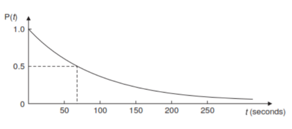
Holding time: The average holding time or service time ‘h’ is the average duration of occupancy of a traffic path by a call. For voice traffic, it is the average holding time per call in hours or 100 seconds and for data traffic, average transmission per message in seconds. The reciprocal of the average holding time referred to as service rate (µ) in calls per hour is given as µ =1/h Sometimes, the statistical distribution of holding time is needed. The distribution leads to a convenient analytic equation. The most commonly used distribution is the negative exponential distribution. The probability of a call lasting at least t seconds is given by P(t) = exp (– t/h) For a mean holding time of h = 100 seconds, the negative exponential distribution function is shown in Fig.
Distribution of destinations: Number of calls receiving at an exchange may be destined to its own exchange or remoted exchange or a foreign exchange. The destination distribution is described as the probability of a call request being for particular destination. As the hierarchical structure of telecommunication network includes many intermediate exchanges, the knowledge of this parameter helps in determining the number of trunks needed between individual centres.
User behaviour: The statistical properties of the switching system are a function of the behaviour of users who encounter call blocking. The system behaves differently for different users. The user may abandon the request if his first attempt to make a call is failed. The user may make repeated attempts to setup a call. Otherwise, the user may wait some times to make next attempt to setup a call. This behaviour varies person to person and also depends on the situation.
Average occupancy: If the average number of calls to and from a terminal during a period T seconds is ‘n’ and the average holding time is ‘h’ seconds, the average occupancy of the terminal is given by A = nh/T =λh=λ/μ Thus, average occupancy is the ratio of average arrival rate to the average service rate. It is measured in Erlangs. Average occupancy is also referred as traffic flow or traffic intensity or carried traffic.
Traffic Pattern
An understanding of the nature of telephone traffic and its distribution with respect to time (traffic load) which is normally 24 hours is essential. It helps in determining the amount of lines required to serve the subscriber needs. According to the needs of telephone subscribers, the telephone traffic varies greatly. The variations are not uniform and varies season to season, month to month, day to day and hour to hour. But the degree of hourly variations is greater than that of any other period. Various parameters related to traffic pattern are discussed below:
Busy hour: Traditionally, a telecommunication facility is engineered on the intensity of traffic during the busy hour in the busy session. The busy hour vary from exchange to exchange, month to month and day to day and even season to season. The busy hour can be defined in a variety of ways. In general, the busy hour is defined as the 60 minutes interval in a day, in which the traffic is the highest. Taking into account the fluctuations in traffic, CCITT in its recommendations E.600 defined the busy hour as follows.
Busy hour. Continuous 60 minutes interval for which the traffic volume or the number of call attempts is greatest.
Peak busy hour It is the busy hour each day varies from day to day, over a number of days.
Time consistent busy hour: The 1 hour period starting at the same time each day for which the average traffic volume or the number of call attempts is greatest over the days under consideration. In order to simplify the traffic measurement, the busy hour always commences on the hour, half hour, or quarter hour and is the busiest of such hours. The busy hour can also be expressed as a percentage (usually between 10 and 15%) of the traffic occurring in a 24 hour period.
Call completion rate (CCR). Based on the status of the called subscriber or the design of switching system the call attempted may be successful or not. The call completion rate is defined as the ratio of the number of successful calls to the number of call attempts. A CCR value of 0.75 is considered excellent and 0.70 is usually expected.
Busy hour call attempts It is an important parameter in deciding the processing capacity of an exchange. It is defined as the number of call attempts in a busy hour.
Busy hour calling rate It is a useful parameter in designing a local office to handle the peak hour traffic. It is defined as the average number of calls originated by a subscriber during the busy hour.
Day-to-day hour traffic ratio It is defined as the ratio of busy hour calling rate to the average calling rate for that day. It is normally 6 or 7 for rural areas and over 20 for city exchanges.
Units of Telephone Traffic
Traffic intensity is measured in two ways. They are (a) Erlangs and (b) Cent call seconds (CCS).
Erlangs. The international unit of traffic is the Erlangs. It is named after the Danish Mathematician, A.K. Erlang, who laid the foundation to traffic theory in the work he did for the Copenhagen telephone company starting 1908. A server is said to have 1 erlang of traffic if it is occupied for the entire period of observation. More simply, one erlang represents one circuit occupied for one hour. The maximum capacity of a single server (or channel) is 1 erlang (server is always busy). Thus, the maximum capacity in erlangs of a group of servers is merely equal to the number of servers.
Cent call seconds (CCS) It is also referred as hundred call seconds. CCS as a measure of traffic intensity is valid only in telephone circuits. CCS represents a call time product. This is used as a measure of the amount of traffic expressed in units of 100 seconds. Sometimes call seconds (CS) and call minutes (CM) are also used as a measure of traffic intensity. The relation between erlang and CCS is given by 1E = 36 CCS = 3600 CS = 60 CM
Grade of Service (GOS) For non-blocking service of an exchange, it is necessary to provide as many lines as there are subscribers. But it is not economical. So, some calls have to be rejected and retried when the lines are being used by other subscribers. The grade of service refers to the proportion of unsuccessful calls relative to the total number of calls. GOS is defined as the ratio of lost traffic to offered traffic.
GOS = Blocked Busy Hour cells/Offered Busy Hour cells
GOS = A-A0/A
Where A0 = carried traffic
A = offered traffic
A – A0 = lost traffic.
The smaller the value of grade of service, the better is the service. The recommended GOS is 0.002, i.e. 2 call per 1000 offered may lost. In a system, with equal no. Of servers and subscribers, GOS is equal to zero. GOS is applied to a terminal to terminal connection. But usually a switching centre is broken into following components
(a) an internal call (subscriber to switching office)
(b) an outgoing call to the trunk network (switching office to trunk)
(c) the trunk network (trunk to trunk)
(d) a terminating call (switching office to subscriber).
The GOS calculated for each component is called component GOS. The overall GOS is in fact approximately the sum of the component grade of service. There are two possibilities of call blocking. They are (a) Lost system and (b) Waiting system. In lost system, a suitable GOS is a percentage of calls which are lost because no equipment is available at the instant of call request. In waiting system, a GOS objective could be either the percentage of calls which are delayed or the percentage which are delayed more than a certain length of time.
Blocking Probability and Congestion
The value of the blocking probability is one aspect of the telephone company’s grade of service. The basic difference between GOS and blocking probability is that GOS is a measure from subscriber point of view whereas the blocking probability is a measure from the network or switching point of view. Based on the number of rejected calls, GOS is calculated, whereas by observing the busy servers in the switching system, blocking probability will be calculated. The blocking probabilities can be evaluated by using various techniques. Lee graphs and Jacobaeus methods are popular and accurate methods. The blocking probability B is defined as the probability that all the servers in a system are busy. Congestion theory deals with the probability that the offered traffic load exceeds some value. Thus, during congestion, no new calls can be accepted. There are two ways of specifying congestion. They are time congestion and call congestion. Time congestion is the percentage of time that all servers in a group are busy. The call or demand congestion is the proportion of calls arising that do not find a free server. In general GOS is called call congestion or loss probability and the blocking probability is called time congestion. If the number of sources is equal to the number of servers, the time congestion is finite, but the call congestion is zero. When the number of sources is large, the probability of a new call arising is independent of the number already in progress and therefore the call congestion is equal to time congestion.
Analysis of the traffic provides information like the average load, the bandwidth requirements for different applications, and numerous other details. Traffic models enables network designers to make assumptions about the networks being designed based on past experience and also enable prediction of performance for future requirements. Traffic models are used in two fundamental ways:
(1) as part of an analytical model or
(2) to drive a Discrete Event Simulation (DES).
Simple traffic comprises of single arrivals of discrete entities, viz., packets, cells, etc. This kind of traffic can be expressed mathematically as a Point Process. A point process consists of a sequence of arrival instants T1, T2, T3... Tn (by convention, T0 = 0). Point processes can be described as a Counting Process or Inter-Arrival Time (IAT) Process. A counting process N(t) is a continuous time, non-negative, integer-valued stochastic process, where N(t) = max{n:Tn ≤ t} denotes the number of (traffic) arrivals in the time interval (0,t][Frost94]. An inter-arrival process is a non-negative random sequence {An}, where An = Tn – Tn-1 is the length of the time interval separating the nth arrival from the previous one. Discrete-time traffic processes are characterized by slotted time intervals. In other words, the random variables An can assume only
Poisson Distribution Model
One of the most widely used and oldest traffic model is the Poisson Model. The memoryless Poisson distribution is the predominant model used for analyzing traffic in traditional telephony networks. The Poisson process is characterized as a renewal process. In a Poisson process the inter-arrival times are exponentially distributed with a rate parameter λ: P{An ≤ t} = 1 – exp(-λt). The Poisson distribution is appropriate if the arrivals are from a large number of independent sources, referred to as Poisson sources. The distribution has a mean and variance equal to the parameter λ. The Poisson distribution can be visualized as a limiting form of the binomial distribution, and is also used widely in queueing models. There are a number of interesting mathematical properties exhibited by Poisson processes. Primarily, superposition of independent Poisson processes results in a new Poisson process whose rate is the sum of the rates of the independent Poisson processes. Further, the independent increment property renders a Poisson process memoryless. Poisson processes are common in traffic applications scenarios that comprise of a large number of independent traffic streams. The reason behind the usage stems from Palm's Theorem which states that under suitable conditions, such large number of independent multiplexed streams approach a Poisson process as the number of processes grows, but the individual rates decrease in order to keep the aggregate rate constant. Nevertheless, it is to be noted that traffic aggregation need not always result in a Poisson process. The two primary assumptions that the Poisson model makes are:
1. The number of sources is infinite
2. The traffic arrival pattern is random.
The probability distribution function and density function of the model are given as:
F(t) = 1 – e -λt
f(t) = λ e -λt
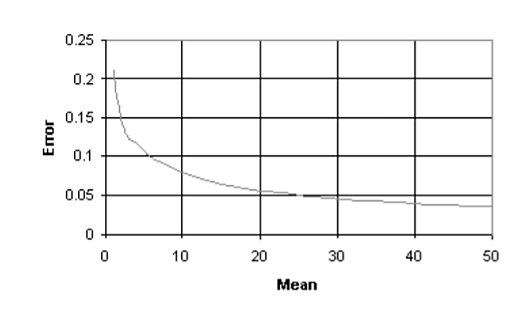
There are also other variations of the Poisson distributed process that are widely used. There are for example, the Homogeneous Poisson process and Non-Homogeneous Poisson process that are used to represent traffic characteristics. An interesting observation in case of Poisson models is that as the mean increases, the properties of the Poisson distribution approach those of the normal distribution.

The implication is that for Poisson distributions with means greater than 30 and subject to the accuracy required it is possible to use the normal distribution as an approximation.
Bernoulli processes are the discrete time analog of Poisson processes. In a Bernoulli process the probability of an arrival in any time slot is p, independent of any other one. The time between arrivals corresponds to a Geometric distribution.
Pareto Distribution Process
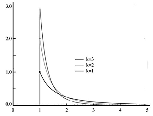
The Pareto distribution process produces independent and identically distributed (IID) inter-arrival times. In general if X is a random variable with a Pareto distribution, then the probability that X is greater than some number x is given by
P(X > x) = (x/xm) -k for all x ≥ xm
Where k is a positive parameter and xm is the minimum possible value of Xi
The probability distribution and the density functions are represented as:
F(t) = 1 – (α/t)β where α,β ≥ 0 & t ≥ α
f(t) = βαβ t-β-1
The parameters β and α are the shape and location parameters, respectively. The Pareto distribution is applied to model self-similar arrival in packet traffic. It is also referred to as double exponential, power law distribution. Other important characteristics of the model are that the Pareto distribution has infinite variance, when β ≥ 2 and achieves infinite mean, when β ≤ 1
Weibull Distribution Process
The Weibull distributed process is heavy-tailed and can model the fixed rate in ON period and ON/OFF period lengths, when producing self-similar traffic by multiplexing ON/OFF sources. The distribution function in this case is given by:
F(t) = 1 – e-(t/β)α t > 0
And the density function of the weibull distribution is given as:
f(t) = αβ-α tα-1 e-(t/β)αt > 0 where parameters β ≥ 0 and α > 0 are the scale and location parameters respectively.
The Weibull distribution is close to a normal distribution. For β ≤ 1 the density function of the distribution is L shaped and for values of β > 1, it is bell shaped. This distribution gives a failure rate increasing with time. For β > 1, the failure rate decreases with time. At, β = 1, the failure rate is constant and the lifetimes are exponentially distributed.
Markov and Embedded Markov Models
Markov models attempt to model the activities of a traffic source on a network, by a finite number of states. The accuracy of the model increases linearly with the number of states used in the model. However, the complexity of the model also increases proportionally with increasing number of states. An important aspect of the Markov model - the Markov Property, states that the next (future) state depends only on the current state. In other words the probability of the next state, denoted by some random variable Xn+1, depends only on the current state, indicated by Xn, and not on any other state Xi, where i<n
A Semi-Markov model is one that is obtained by allowing the time between state transitions to follow an arbitrary probability distribution. The time distribution between state transitions can also be ignored. In this model, the state transitions are then modeled as discontinuous entities with respect to time. The MC developed under such an assumption, is also referred to as an Embedded or Discrete Markov chain.
ON-OFF and IPP Models
The design & development of an ON-OFF model relies on a accurate description of traffic entities from link level to application level. The model is generally used, when it is necessary to capture the scaling behaviors of network traffic. For instance, analysis of the structure of IP traffic is performed predominantly using ON-OFF models. The ON-OFF model uses only two states, namely ON & OFF. The time spent between the ON & OFF states, commonly referred to as the transition time, is expected to follow an exponential distribution. The subsequent queueing analysis of multiplexed ON-OFF sources would detail the development of the model. To understand the ON-OFF model, let us consider a queue/link in a network, shared by N different ON-OFF sources, as shown in Figure.
For the ON-OFF model to be used in this scenario, it is required that the sources are statistically identical and independent. The queue of size M is served by a constant rate C, by the source. The ON-OFF source is characterized by L - the mean number of packets/cells generated during the ON state, the peak rate S when the source is ON, and the mean source rate r. These factors determine the mean durations of the ON & OFF periods of the source. The equilibrium probability in the ON phase of the source is calculated as, γ = r/S
With the ON-OFF periods exponentially distributed, the source can be modeled by a two-state Markov chain. The mean rate of packet/cell generation is assumed to be strictly greater then 1, L >> . The transition rates of the source, from the OFF state to the ON state and vice-versa, is calculated as
t1 (from the Off to the on state): γS / (L(1-y))
t2 (from the On to the Off state): S / L
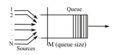
Figure 2 Example queueing analysis for ON-OFF models
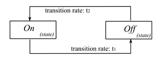
Figure 3 Simple ON-OFF Model with transitional rates t1 & t2
The Interrupted Poisson Process (IPP) is yet another two state process. The network channel is one of the two states, ON or OFF. In a discrete time IPP, a packet arrives in each of the time slots of the ON state, following a Bernoulli distribution. Though the IPP model is similar to the ON-OFF model, there is a slight variation that differentiates the two models. The difference is that in case of the IPP model, there is no traffic or in other words, no packets arrive during the OFF state.
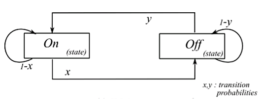
Figure 4 IPP Model framework
Alternating State Renewal Process
Conventional Markov models, though mathematically tractable, fail to fit actual traffic of high speed networks. In high-speed networks the packets are transmitted in a packet train fashion; once such a packet train is triggered, the probability that another packet will follow is very large. Further, the length of the packets exhibit a heavy-tail distribution. This observation led to the well known Alternating State Renewal Process (ASRP). ASRP is another two-state process used to model network traffic. Though there are only two states, S1 and S2, similar to the previous two-state models discussed, there is no self-transition in this model. The amplitude of the traffic in state S1 is 0 and 1 in the state S2. The mean time taken for transition between the two states, is denoted by d1 & d2 respectively. The ASRP model can be visualized as an Embedded Markov Chain (EMC) varying between the two states of the model. The probabilities for being in the individual states can be calculated using the simple formulae, Ps1 = d1 / (d1+d2) and Ps2 = d2 / (d1+d2).
Markov Modulated Poisson Process
The Markov Modulated Poisson Process (MMPP) is a widely used tool for analysis of tele traffic models. The model is preferred for its high versatility in qualitative behavior. It allows to capture network traffic sources that are bursty in nature. A Markov Modulated Process (MMP) employs an auxiliary Markov process, in which the current state of the Markov process controls the probability distribution of the traffic. MMPP is a variation of a Markov modulated process, where the auxiliary process used is a Poisson distributed process. In other words, MMPP is a doubly stochastic process where the intensity of a Poisson process is defined by the state of a MC.
The MC can be visualized to modulate the Poisson process. The MMPP is also identified as a special case of the Markovian Arrival Process (MAP). MMPPs are classified by the number of states present in the modulating MC. An MC with two states and two different intensities is referred as MMPP-2. It is also called sometimes as a Switched Poisson Process (SPP). An interesting feature to observe in this case, is that when the two intensities are equal, then the model transforms to a typical Poisson process.
IPP is a special case of an MMPP, where either of the intensity is zero. Another important aspect of MMPP is that a superposition of MMPPs is also a MMPP. An MMPP with M + 1 number of states, can be obtained by superposition of M identical and independent IPP sources. The use of a Poisson distributed process in MMPP implies that the arrival rates of sources have Poisson distribution with a rate denoted by λk. MMPP model can be used for analyzing a mixture of voice and data traffic.
In that case, the arrival rates are still assumed to exhibit a Poisson distribution. Therefore, the traffic is assumed to be comprised of voice and data packets, together adding up to the overall traffic on the network. However, though the arrival rates of both the types of traffic, voice and data are Poisson in nature, the rates of the individual packets can be different. Considering, hence, Poisson distribution for data packets with a rate λd and assuming that voice packets also follow Poisson distribution, however, with a different rate λV, the resulting rate at any particular state Si is given by Si = λd + λv.
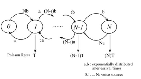
Figure 5 Model graph of MMPP showing superposition of N voice sources
Markov Modulated Fluid Models
Fluid flow models are conceptually simple. For instance, event simulation for an ATM multiplexer has several advantages, when fluid flow models are used for the simulation. Models other than the fluid flow models, that distinguish between the cells and consider the arrival of each cell as a separate event, typically consume huge amounts of memory and CPU time for the simulation. On the contrary, a fluid flow model that characterizes the incoming cells by a finite flow rate, require comparatively less resources. This is because in a fluid flow model, an event is generated only when the flow rate changes; and changes in flow rates are less frequent compared to the arrivals of cells. A fluid flow model as a consequence, utilizes lesser computing power and memory resources, compared to simulation using other models.
The basic feature of a fluid model is to characterize the traffic on a network as a continuous stream of input with a finite flow/stream rate. In other words, the incoming traffic rate is represented as a stream with a finite rate. By capturing the rate changes at the input, the models analyse the different events that occur in the network. Because of the simple method of characterization of traffic, the fluid modes are analytically tractable and easier to simulate. Like any other Markov modulated process the Markov Modulated Fluid Model (MMFM), uses an underlying MC that determines the rate of the sources. At any instant, the current state of the underlying MC determines the flow rate of the inputs.
Autoregressive Models
The Autoregressive model is one of a group of linear prediction formulas that attempt to predict an output yn of a system based on previous set of outputs {yk} where k < n and inputs xn and {xk} where k < n. There exist minor changes in the way the predictions are computed based on which, several variations of the model are developed. Basically, when the model depends only on the previous outputs of the system, it is referred to as an auto-regressive model. It is referred to as a Moving Average Model (MAM), if it depends on only the inputs to the system. Finally, Autoregressive-Moving Average models are those that depend both on the inputs and the outputs, for prediction of current output. Autoregressive model of order p, denoted as AR(p), has the following form:
Xt = R1 Xt-1 + R2 Xt-2 + ... + Rp Xt-p + Wt
Where Wt is the white noise, Ri are real numbers and Xt are prescribed correlated random numbers. The auto-correlation function of the AR(p) process consists of damped sine waves depending on whether the roots (solutions) of the model are real or imaginary. Discrete Autoregressive Model of order p, denoted as DAR(p), generates a stationary sequence of discrete random variables with a probability distribution and with an auto-correlation structure similar to that of the Autoregressive model of order p.
Key takeaway
The different traffic models each have its own pros and cons. The type of network under study and the traffic characteristics strictly influences the choice of the traffic model used for analysis. Traffic models that cannot capture or describe the statistical characteristics of the actual traffic on the network are to be avoided, since the choice of such models will result in under-estimation or over-estimation of network performance.
There is no one single model that can be used effectively for modeling traffic in all kinds of networks. For heavy-tailed traffic, it can be shown that Poisson model under-estimates the traffic. In case of high speed networks with unexpected demand on packet transfers, Pareto based traffic models are excellent candidates since the model takes into the consideration the long-term correlation in packet arrival times.
Similarly, with Markov models, though they are mathematically tractable, they fail to fit actual actual traffic of high-speed networks. Other than the traffic models discussed in this report there are numerous other traffic models, that are used widely for traffic modeling. There are different categories of traffic models like stationary and non-stationary types.
Stationary models can further be subdivided into models that are referred to as Short-range dependent and Long-range dependent types. Each model varies significantly from the other and is suitable for modeling different traffic characteristics.
A number of factors come into play while evaluating the efficiency of a traffic model. In general, the factor that differentiates one model from the other is the ability to model various correlation patterns and marginal distributions. Traffic models should have a manageable number of parameters, and parameter estimation should be simple; and, models that are not analytically tractable are preferred only for generating traffic traces.
References:
1. Cristopher Cox, “An Introduction to LTE: LTE, LTE-Advanced, SAE, VoLTE and 4G Mobile Communications”, Wiley, 2nd Edition.
2. E. Dahlman, J. Skold, and S. Parkvall, “4G, LTE-Advanced Pro and The Road to 5G”, Academic Press, 3rd Edition.
3. B. P. Lathi, “Modern Digital and Analog Communications Systems”. Oxford university press, 2015, 4th Edition.
4. Obaidat, P. Nicopolitids, “Modeling and simulation of computer networks and systems: Methodologies and applications” Elsevier, 1st Edition.