Unit - 6
Performance Analysis Issues
- CDMA systems spread symbols. Before spreading symbols it uses distinctive code before transmission.
- On receiver side all symbols accepted by dispreading with help of correlating symbols. A signal which does not required are neither correlate nor de-spread to accept.
- CDMA signals are sequence of 0’s and 1’s and sequences are generated from code. Symbol per second means original data rate and chip rates means code chipping rate.
- Every code belongs to distinct set of data.
- CDMA allows space, time frequency signals transmission.
Different coding method used in CDMA are :
(a) Autocorrelation codes
(i) Barker code.
(ii) Pseudo-noise code.
(b) Other important codes
(i) Orthogonal codes.
(ii) Walsh codes.
(iii) Scrambling codes.
(iv) Channelization codes.
(v) Carrier modulation codes.
Autocorrelation codes
Barker code
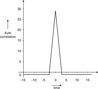
Fig.1: Autocorrelation function of balanced 11 chip barker code
- Comparison of signals against itself means auto correlation. Comparison made on basis number of matching bits.
- Codes are designed to have desirable autocorrelation properties as well as cross correlation properties.
- An auto correlate code is a multi bit code. Multi bit code used to code symbols before transmission and allow receiver to correlate code.
- Extraction of symbols done automatically at receiver end.
- Barkers code and PN code i.e. pseudo noise code are examples of auto correlation code.
- The correlation side lobe : Ck for k-symbol shift of an N-bit code sequence, {xj} given by :
Ck = Xi Xj + k
Xj – individual code.
- Barker code generator provides code as shown in Table1.
Table 1: Lists of barker code
Code length | Barker code |
1 | [– 1] |
2 | [– 1 1] |
3 | [– 1 – 1 1] |
4 | [– 1 – 1 1 – 1] |
5 | [– 1 – 1 – 1 1 – 1] |
7 | [– 1 – 1 – 1 1 1 – 1 1] |
11 | [– 1 – 1 – 1 1 1 1 – 1 1 1 – 1 1] |
13 | [– 1 – 1 – 1 – 1 – 1 1 1 – 1 – 1 1 – 1 1 – 1] |
Maximum code length with low correlation sidelobes is 13.
Autocorrelation of barker code 7:

Fig. 2: Auto correaltion of barker code 7
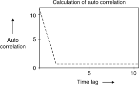
Fig.3: Auto correaltion of barker code 11
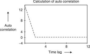
Fig.4: Auto correlation of barker code 13
Pseudo-Noise Code
- Pseudo-Noise (PN) also known Pseudo Random Binary Sequence (PRBS).
- A Pseudo-Noise code (PN-code) or Pseudo Random Noise Code (PRN code) is a spectrum which generated deterministically by random sequence.
- PN sequence is random occurance of 0’s and 1’s bit stream.
- Directly sequence spread spectrum (DS-SS) system is most popular sequence in DS-SS system bits of PN sequence is known as chips and inverse of its period is known as chip rate.
In frequency hopping spread spectrum (FH-SS) sequence, channel number are pseudo random sequences and hop rate are inverse of its period.
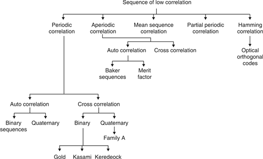
Fig.5: Overview of PN sequence
Properties
(i) Balance property:
Total no. Of 1’s is more than no. Of 0’s in maximum length sequence.
(ii) Run property 1’s and 0’s stream shows length sequence, every fraction relate some meaning.
Rum | Length |
1/2 | 1 |
1/4 | 2 |
1/8 | 3 |
(iii) Correlation property:
If compared sequences are found similar then it is auto coreelation.
If compared sequences are found mismatched then it is cross correlation.
Let (K) and y (K) are two sequences then correlation R (m) will be:

Correlation R (m) in pattern of digital bit sequence will be:

y1 = P1 q1
y1 = 0 if P1 q1
y1 = 1 if P1 = q1
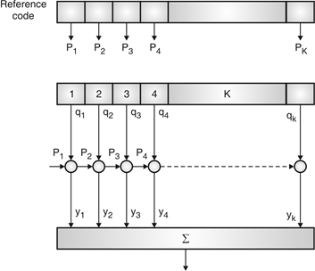
Fig.6: Correlator
Fig. 6 shows Pi is a sequence which shifts through K bit shift register. K is length of correlate. Output achieved by K XNOR gate after comparison.
(iv) Shift and add:
By using X-OR gate, shift sequence modulo-2 added to upshifted sequence.
PN sequence generation methodologies :
(i) Using shift register with feedback.
(ii) Series parallel method for high speed PN generation.
(iii) Avoiding zero state.
(iv) Barker sequence.
(v) Kasami sequence.
(vi) Gold sequence.
Orthogonal Codes
If two codes are multiplied together then their added result sum becomes zero over a period of time; such code is said to be orthogonal code.
Walsh Codes
- These are mutually orthogonal error correcting codes.
- It is linear code. It maps binary strings (length n) to binary codeword and codewords are of length 2n.
- It is used to obtain 2n bit orthogonal codewords from n bit messages.
- Example WC sequence generation :

Generation of walsh code matrices.


W8 | = |
| 0 | 0 | 0 | 0 | 0 | 0 | 0 |
|
| 0 | 1 | 0 | 0 | 1 | 0 | 1 |
| ||
| 0 | 0 | 1 | 0 | 0 | 1 | 1 |
| ||
| 0 | 1 | 1 | 0 | 1 | 1 | 0 |
| ||
| 0 | 0 | 0 | 1 | 1 | 1 | 1 |
| ||
| 0 | 1 | 0 | 1 | 0 | 1 | 0 |
| ||
| 0 | 0 | 1 | 1 | 1 | 0 | 0 |
| ||
| 0 | 1 | 1 | 1 | 0 | 0 | 1 |
|
Walsh code is given as a row in WC matrix code generation basis is as:
“0” “1”
“1” “– 1”
Examples
Codes W4, 2 and W4, 3
W8, 2: (0, 0, 1, 1, 0, 0, 1, 1) (1, 1, – 1, – 1, 1, 1,– 1, – 1)
W8, 3: (0, 1, 1, 0, 0, 1, 1, 0) (1, – 1, – 1, 1, 1, – 1,– 1, 1)
When codes are synchronized, codes are found orthogonal.
W8, 2 W8, 3 : (1, 1, – 1, – 1, 1, 1, – 1, – 1) (1, – 1, – 1, 1, 1, 1,– 1, – 1, 1)
W8, 2 W8, 3: 0
When codes are synchronous, codes are not orthogonal.
W8, 2 shift (W8, 3, 1) = (1, 1, – 1, – 1, 1, 1, – 1, – 1) (1, 1, – 1, – 1, 1, 1,– 1, – 1)
W8, 2 shift (W8, 3, 1) = 8
Scrambling Code
- Pseudo random scrambling code is used to multiply with sequence code to complete scrambling process. It may be a long code or short code.
- Scrambling code are considered in downlink and uplink separately.
- Primary Scrambling Code (PSC) and Secondary Scrambling Code (SSC) are two types of scrambling code in downlink. There are 512 PSC and only one PSC per sector. SSC has many codes preferred in beam forming cases.
- In uplink, long scrambling code are used.
- It has several millions of codes.
- Usage of scrambling code :
- Uplink scrambling code used in separation of terminals.
- Downlink scrambling code used for separation of cells/terminals.
- No spreading, doesn’t affect transmission bandwidth.
Channelisation Code
- It is based on orthogonal variable spreading factor (OVSF) technique.
- In uplink, code can separate physical channel or service of one user.
- In downlink, code can separate different users within one cell as sector. Spreading factor or length of code used to decide speed of the channel. If small length then high data transmission and vice-versa.
Differentiate between CDMA and GSM
CDMA and GSM are differentiated on several parameters shown below.
| CDMA | GSM |
Stands for | Code Division Multiple Access | Global System for Mobile communication |
Storage Type | Internal Memory | SIM card (subscriber identity module) |
Global market share | 25% | 75% |
Dominance | Dominant standard in the U.S. | Dominant standard worldwide except the U.S. |
Data transfer | EVDO/3G/4G/LTE | GPRS/E/3G/4G/LTE |
Network | There is one physical channel and a special code for every device in the coverage network. Using this code, the signal of the device is multiplexed, and the same physical channel is used to send the signal. | Every cell has a corresponding network tower, which serves the mobile phones in that cellular area. |
International roaming | Less Accessible | Most Accessible |
Frequency band | Single (850 MHz) | Multiple (850/900/1800/1900 MHz) |
Network service | Handset specific | SIM specific. User has option to select handset of his choice. |
Binary cyclic codes are a subclass of the linear block codes. They have very good features which make them extremely useful. Cyclic codes can correct errors caused by bursts of noise that affect several successive bits. The very good block codes like the Hamming codes, BCH codes and Golay codes are also cyclic codes. A linear block code is called as cyclic code if every cyclic shift of the code vector produces another code vector. A cyclic code exhibits the following two properties.
(i) Linearity Property: A code is said to be linear if modulo-2 addition of any two code words will produce another valid codeword.
(ii) Cyclic Property: A code is said to be cyclic if every cyclic shift of a code word produces another valid code word. For example, consider the n-bit code word, X = (xn-1, xn-2, ….. x1, x0).
If we shift the above code word cyclically to left side by one bit, then the resultant code word is
X’ = (xn-2, xn-3, ….. x1, x0, xn-1)
Here X’ is also a valid code word. One more cyclic left shift produces another valid code vector X’’.
X’’ = (xn-3, xn-4, ….. x1, x0, xn-1, xn-2)
Representation of codewords by a polynomial
The cyclic property suggests that we may treat the elements of a code word of length n as the coefficients of a polynomial of degree (n-1).
Consider the n-bit code word, X = (xn-1, xn-2, ….. x1, x0)
This code word can be represented in the form of a code word polynomial as below:
X (p) = xn-1p n-1 + xn-2pn-2 + ….. + x1p + x0
Where X (p) is the polynomial of degree (n-1). p is an arbitrary real variable. For binary codes, the coefficients are 1s or 0s.
- The power of ‘p’ represents the positions of the code word bits. i.e., pn-1 represents MSB and p0 represents LSB.
- Each power of p in the polynomial X(p) represents a one-bit cyclic shift in time. Hence, multiplication of the polynomial X(p) by p may be viewed as a cyclic shift or rotation to the right, subject to the constraint that pn = 1.
- We represent cyclic codes by polynomial representation because of the following reasons.
1. These are algebraic codes. Hence algebraic operations such as addition, subtraction, multiplication, division, etc. becomes very simple.
2. Positions of the bits are represented with the help of powers of p in a polynomial.
A) Generation of code vectors in non-systematic form of cyclic codes
Let M = (mk-1, mk-2, …… m1, m0) be ‘k’ bits of message vector. Then it can be represented by the polynomial as,
M(p) = mk-1pk-1 + mk-2pk-2 + ……+ m1p + m0
The codeword polynomial X(P) is given as X (P) = M(P) . G(P)
Where G(P) is called as the generating polynomial of degree ‘q’ (parity or check bits q = n – k). The generating polynomial is given as G (P) = pq + gq-1pq-1+ …….. + g1p + 1
Here gq-1, gq-2 ….. g1 are the parity bits.
• If M1, M2, M3, …… etc. are the other message vectors, then the corresponding code vectors can be calculated as,
X1 (P) = M1 (P) G (P)
X2 (P) = M2 (P) G (P)
X3 (P) = M3 (P) G (P) and so on
All the above code vectors X1, X2, X3 ….. Are in non-systematic form and they satisfy cyclic property.
The generator polynomial of a (7, 4) cyclic code is G(p) = p3 + p + 1. Find all the code vectors for the code in non-systematic form
Here n = 7, k = 4
Therefore, q = n – k = 7 – 4 = 3
Since k = 4, there will be a total of 2k = 24 = 16 message vectors (From 0 0 0 0 to 1 1 1 1). Each can be coded in to a 7 bits codeword.
(i) Consider any message vector as
M = (m3 m2 m1 m0) = (1 0 0 1)
The general message polynomial is M(p) = m3p3 + m2p2 + m1p + m0, for k = 4
For the message vector (1 0 0 1), the polynomial is
M(p) = 1. p3 + 0. p2 + 0. p + 1
M(p) = P3 + 1
The given generator polynomial is G(p) = p3 + p + 1
In non-systematic form, the codeword polynomial is X (p) = M (p). G (p)
On substituting,
X (p) = (p3 + 1). (p3 + p +1)
= p6 + p4 + p3 + p3 + p +1
= p6 + p4 + (1 1) p3 + p +1
= p6 + p4 + p + 1
= 1.p6 + 0.p5 + 1.p4 + 0.p3 + 0.p2 + 1.p + 1
The code vector corresponding to this polynomial is
X = (x6 x5 x4 x3 x2 x1 x0)
X = (1 0 1 0 0 1 1)
(ii) Consider another message vector as
M = (m3 m2 m1 m0) = (0 1 1 0)
The polynomial is M(p) = 0.p3 + 1.p2 + 1.p1 + 0.1
M(p) = p2 + p
The codeword polynomial is
X(p) = M(p). G(p)
X(p) = (p2 + p). (p3 + p + 1)
= p5 + p3 + p2 + p4 + p2 + p
= p5 + p4 + p3 + (1 1) p2 + p
= p5 + p4 + p3 + p
= 0.p6 + 1.p5 + 1.p4 + 1.p3 + 0.p2 + 1.p + 0.1
The code vector, X = (0 1 1 1 0 1 0)
Similarly, we can find code vector for other message vectors also, using the same procedure.
B) Generation of code vectors in systematic form of cyclic codes
The code word for the systematic form of cyclic codes is given by
X = (k message bits ⋮q check bits)
X = (mk-1 mk-2 …….. m1 m0⋮ cq-1 cq-2 ….. c1 c0)
In polynomial form, the check bits vector can be written as
C(p) = cq-1pq-1 + cq-2pq-2 + …….. + c1p + c0
In systematic form, the check bits vector polynomial is obtained by
C(p) = rem [𝑝𝑞. 𝑀 (𝑝)/𝐺(𝑝) ]
Where:
M(p) is message polynomial
G(p) is generating polynomial
‘rem’ is remainder of the division
The generator polynomial of a (7, 4) cyclic code is G(p) = p3 + p + 1. Find all the code vectors for the code in systematic form.
Here n = 7, k = 4
Therefore, q = n - k = 7 – 4 = 3
Since k = 4, there will be a total of 2k = 24 = 16 message vectors (From 0 0 0 0 to 1 1 1 1). Each can be coded into a 7 bits codeword.
(i) Consider any message vector as
M = (m3 m2 m1 m0) = (1 1 1 0)
By message polynomial,
M(p) = m3p3 + m2p2 + m1p + m0, for k = 4.
For the message vector (1 1 1 0), the polynomial is
M(p) = 1.p3 + 1.p2 + 1.p + 0.1
M(p) = p3 + p2 + p
The given generator polynomial is G(p) = p3 + p + 1
The check bits vector polynomial is

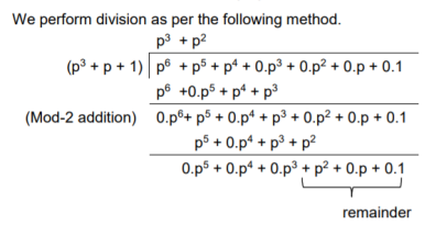
Thus, the remainder polynomial is p2 + 0.p + 0.1.
This is the check bits polynomial C(p)
c(p) = p2 + 0.p + 0.1
The check bits are c = (1 0 0)
Hence the code vector for the message vector (1 1 1 0) in systematic form is
X = (m3 m2 m1 m0⋮ c2 c1 c0) = (1 1 1 0 1 0 0)
(ii) Consider another message vector as
M = (m3 m2 m1 m0) = (1 0 1 0)
The message polynomial is M(p) = p3 + p
Then the check bits vector polynomial is
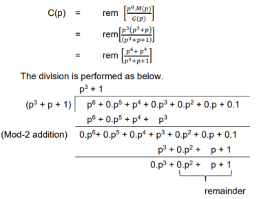
Thus, the check bits polynomial is C(p) = 0.p2 + 1.p + 1.1
The check bits are C = (0 1 1)
Hence the code vector is X= (1 0 1 0 0 1 1)
Similarly, we can find code vector for other message vectors also, using the same procedure.
Cyclic Redundancy Check Code (CRC)
Cyclic codes are extremely well-suited for error detection. Because they can be designed to detect many combinations of likely errors. Also, the implementation of both encoding and error detecting circuits is practical. For these reasons, all the error detecting codes used in practice are of cyclic code type. Cyclic Redundancy Check (CRC) code is the most important cyclic code used for error detection in data networks & storage systems. CRC code is basically a systematic form of cyclic code.
CRC Generation (encoder)
The CRC generation procedure is shown in the figure below.
- Firstly, we append a string of ‘q’ number of 0s to the data sequence. For example, to generate CRC-6 code, we append 6 number of 0s to the data.
- We select a generator polynomial of (q+1) bits long to act as a divisor. The generator polynomials of three CRC codes have become international standards. They are
- CRC – 12 code: p12 + p11 + p3 + p2 + p + 1
- CRC – 16 code: p16 + p15 + p2 + 1
- CRC – CCITT Code: p16 + p12 + p5 + 1

Fig 7 CRC Generation
- We divide the data sequence appended with 0s by the divisor. This is a binary division.
- The remainder obtained after the division is the ‘q’ bit CRC. Then, this ‘q’ bit CRC is appended to the data sequence. Actually, CRC is a sequence of redundant bits.
- The code word generated is now transmitted.
CRC checker
The CRC checking procedure is shown in the figure below. The same generator polynomial (divisor) used at the transmitter is also used at the receiver.
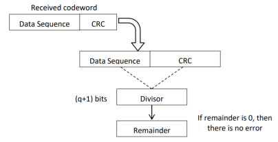
Fig 8 CRC checker
- We divide the received code word by the divisor. This is also a binary division.
- If the remainder is all 0s, then there are no errors in the received codeword, and hence must be accepted.
- If we have a non-zero remainder, then we infer that error has occurred in the received code word. Then this received code word is rejected by the receiver and an ARQ signalling is done to the transmitter.
Generate the CRC code for the data word of 1 1 1 0. The divisor polynomial is p3 + p + 1
Data Word (Message bits) = 1 1 1 0
Generator Polynomial (divisor) = p3 + p + 1
Divisor in binary form = 1 0 1 1
The divisor will be of (q + 1) bits long. Here the divisor is of 4 bits long. Hence q = 3. We append three 0s to the data word.
Now the data sequence is 1 1 1 0 0 0 0. We divide this data by the divisor of 1 0 1 1. Binary division is followed.
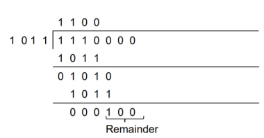
The remainder obtained from division is 100. Then the transmitted codeword is 1 1 1 0 1 0 0.
A codeword is received as 1 1 1 0 1 0 0. The generator (divisor) polynomial is p3 + p + 1. Check whether there is error in the received codeword.
Received Codeword = 1 1 1 0 1 0 0
Divisor in binary form = 1 0 1 1
We divide the received codeword by the divisor.
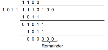
The remainder obtained from division is zero. Hence there is no error in the received codeword.
Key takeaway
- Cyclic codes can correct burst errors that span many successive bits.
- They have an excellent mathematical structure. This makes the design of error correcting codes with multiple-error correction capability relatively easier.
- The encoding and decoding circuits for cyclic codes can be easily implemented using shift registers.
- The error correcting and decoding methods of cyclic codes are simpler and easy to implement. These methods eliminate the storage (large memories) needed for lookup table decoding. Therefore, the codes become powerful and efficient.
Consider the problem of varying transmit power to satisfy fixed target SIR constraints γ and minimize the total power.
Minimize 
Subject to SIRi(p)
 I
I
In the above and all of the following optimization problems, we omit non-negativity constraints on variables.
Above equation can be optimised as
Minimise 1Tp
Subject to (I-D( F)p
F)p  v
v
Where I is the identity matrix, and
v= D( = (
= ( I
I  1/G11 ,
  2
2  2/G22,……..
  n
n  n/Gnn) T
Where t = 1, 2, . . . , and SIRi [t] is the received SIR at the tth iteration. In the above and all of the following iterative algorithms, we omit the iteration loop with t = t + 1.
The update is distributed as each user only needs to monitor its individual received SIR and can update by independently and asynchronously [189]. Intuitively, each user i increases its power when its SIRi [t] is below γi and decreases it otherwise. The optimal power allocation p is achieved in the limit as t → ∞, and satisfies (I−D(γ)F)p ∗ = v, i.e., the constraints in are tight at optimality. The above DPC algorithm has been extensively studied, with results on existence of feasible solution and convergence to optimal solution characterized through several approaches. First is a set of equivalent conditions for SIR feasibility:
Theorem 1 (Existence of a feasible power vector). The following statements are equivalent:
1) There exists a power vector p  0 such that (I − D(γ)F) p
  0.
0.
2) ρ(D(γ)F) < 1.
3) (I−D(γ)F) −1 = Fk
Fk
Exists and is positive component wise, with
 F] k =0
Theorem 2 (Convergence and optimality of DPC algorithm)
If the constraints in above equations have a feasible solution, then
P* = (I-D( )F)‑1)v
Is feasible and power-minimum.
One way to view the DPC algorithm is through the power update to solve the matrix inversion p = (I − D(γ)F) −1v
Theorem 1 is satisfied, the expansion of this matrix inversion as a power series becomes
p[t+1] = D(γ) Fp[t]+v
Maximum power constraint. If we assume a maximum power constraint pmi, a modified form of the DPC algorithm is given as follows
Pi[t+1] = min { (γi /SIR[t]) pi[t], pim}
However, a problem with using above equation is that a user may hit its maximum power ceiling at some iteration t¯ with SIRi [t¯] < γi, and this may result in SIRi [t] < γi for t ≥ t¯, i.e., the SIR constraint is not satisfied even though the user transmits at the maximum power. In this case, it can be shown that the power of those users in the network that satisfy SIRi [t¯] ≥ γi for some t ≥ t¯ will converge to a feasible solution, whereas the other users that cannot achieve the required SIR threshold will continue to transmit at maximum power.
Discrete power levels. The equation over a discrete set of available power levels. Now the above becomes an integer programming problem, which is in general hard to solve for global optimality. In a Minimum Feasible Value Assignment (MFVA) iterative algorithm is developed to solve this integer programming problem. The MFVA algorithm can be made distributed and solved asynchronously. Furthermore, the MFVA algorithm finds the optimal solution in a finite number of iterations which is polynomial in the number of power levels and the number of users in the network.
Standard Interference Function A general framework for uplink power control is proposed by identifying a broad class of iterative power control systems. The SIR of each user can be described by a vector inequality of interference constraints of the form
p I(p).
I(p).
Here, I(p) = [I1(p), . . . , In(p)]T where Ii(p) denotes the interference experienced by user i. A power vector p  0 is feasible if p satisfies (2.9), and an interference function I(p) is feasible if above equation is satisfied. For a system with interference constraint, we examine the following iterative algorithm.
Algorithm 2 (Standard Interference Function Algorithm)
p[t+1] = I(p[t])
Convergence for synchronous and totally asynchronous version of the iteration can be proven when I(p) satisfy the following definition for power vectors p and p ′:
I(p) a standard interference function1 if it satisfies:
1) If p > p ′, then I(p) > I (p ′) (monotonicity property).
2) If c > 1, then cI(p) > I(cp) (scalability property).
The feasibility index RI of a standard interference function I(p) is
RI = max {c
 | p
| p cI(p)
cI(p)
A standard interference function I(p) is feasible if and only if RI > 1.
If a fixed point exists, then the it is unique, and the power vector converges to the fixed point from any initial power vector.
It is readily verified that the power update algorithm is a standard interference function where:
Ii(p) =  i/Gii (
Hence, the DPC algorithm converges under both synchronous and totally asynchronous condition if there exists a feasible solution, and the feasibility index RI, given by 1/ρ(D(γ)F), is larger than 1
Ad hoc network MAC protocols can be classified into three basic types:
- Contention-based protocols
- Contention-based protocols with reservation mechanisms
- Contention-based protocols with scheduling mechanisms
- Other MAC protocols
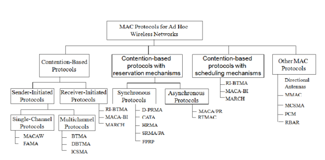
Contention-based protocols
Sender-initiated protocols: Packet transmissions are initiated by the sender node.
- Single-channel sender-initiated protocols: A node that wins the contention to the channel can make use of the entire bandwidth.
- Multichannel sender-initiated protocols: The available bandwidth is divided into multiple channels.
Receiver-initiated protocols: The receiver node initiates the contention resolution protocol.
Contention-based protocols with reservation mechanisms
• Synchronous protocols: All nodes need to be synchronized. Global time synchronization is difficult to achieve.
• Asynchronous protocols: These protocols use relative time information for effecting reservations.
Contention-based protocols with scheduling mechanisms
• Node scheduling is done in a manner so that all nodes are treated fairly and no node is starved of bandwidth.
• Scheduling-based schemes are also used for enforcing priorities among flows whose packets are queued at nodes.
• Some scheduling schemes also consider battery characteristics.
Other protocols are those MAC protocols that do not strictly fall under the above categories. Other MAC protocols Similarly to ad hoc routing protocols discussed earlier, our discussion on MAC protocol issues is also far from being exhaustive. There are many other issues to be considered such as fairness. Fairness has many meanings and one of them might say that stations should receive equal bandwidth.
With the basic approach of IEEE 802.11, this fairness is not easy to accomplish since unfairness will eventually occur when one node backs off much more than some other node. MACAW’s solution to this is to append the contention window value (CW) to packets a node transmits, so that all nodes hearing that CW use it for their future transmissions. Since CW is an indication of the level of congestion in the vicinity of a specific receiver node, MACAW proposes maintaining a CW independently for each receiver. There are also other proposals such as Distributed Fair Scheduling and Balanced MAC.
Contention-based protocols
Contention-based protocols do not have any bandwidth reservation mechanisms. All ready nodes contend for the channel simultaneously, and the winning node gains access to the channel. Since nodes are not guaranteed bandwidth, these protocols cannot be used for transmitting real-time traffic, which requires QoS guarantees from the system.
MACAW: A Media Access Protocol for Wireless LANs MACA was proposed due to the shortcomings of CSMA protocols when used for wireless networks. In what follows, a brief description on why CSMA protocols fail in wireless networks is given. This is followed by detailed descriptions of the MACA protocol and the MACAW protocol.
MACA Protocol: The MACA protocol was proposed as an alternative to the traditional carrier sense multiple access (CSMA) protocols used in wired networks. In CSMA protocols, the sender first senses the channel for the carrier signal. If the carrier is present, it retries after a random period of time. Otherwise, it transmits the packet. CSMA senses the state of the channel only at the transmitter. MACA does not make use of carrier-sensing for channel access. It uses two additional signaling packets: the request-to-send (RTS) packet and the clear-to-send (CTS) packet. When a node wants to transmit a data packet, it first transmits an RTS packet. The receiver node, on receiving the RTS packet, if it is ready to receive the data packet, transmits a CTS packet. Once the sender receives the CTS packet without any error, it starts transmitting the data packet. This data transmission mechanism is depicted in Figure. Hence, the exposed terminal problem is also overcome in MACA. But MACA still has certain problems, which was why MACAW, described below, was proposed.
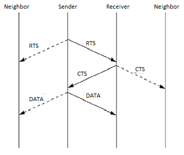
Figure 9 Packet transmission in MACA
MACAW Protocol: The binary exponential back-off mechanism used in MACA at times starves flows. For example, consider Figure. Here both nodes S1 and S2 keep generating a high volume of traffic. The node that first captures the channel (say, node S1) starts transmitting packets. The packets transmitted by the other node S2 get collided, and the node keeps incrementing its back-off window according to the BEB algorithm. As a result, the probability of node S2 acquiring the channel keeps decreasing, and over a period of time it gets completely blocked. To overcome this problem, the back-off algorithm has been modified in MACAW.
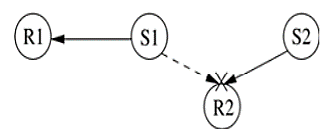
Figure. 10 Example topology
In MACAW another modification related to the back-off mechanism has been made. MACAW implements per flow fairness as opposed to the per node fairness in MACA. This is done by maintaining multiple queues at every node, one each for each data stream, and running the backoff algorithm independently for each queue. A node that is ready to transmit packets first determines how long it needs to wait before it could transmit an RTS packet to each of the destination nodes corresponding to the top-most packets in the node's queues. It then selects the packet for which the waiting time is minimal.

Figure. 11 Example topology.
The MACAW protocol uses one more control packet called the request-for-request-to-send (RRTS) packet. The following example shows how this RRTS packet proves to be useful. Consider Figure. Here assume, the transmission is going on between nodes S1 and R1. Now node S2 wants to transmit to node R2. But since R2 is a neighbor of R1, it receives CTS packets from node R1, and therefore it defers its own transmissions. Node S2 has no way to learn about the contention periods during which it can contend for the channel, and so it keeps on trying, incrementing its back-off counter after each failed attempt. Hence the main reason for this problem is the lack of synchronization information at source S2.
Floor Acquisition Multiple Access Protocols (FAMA) The floor acquisition multiple access (FAMA) protocols are based on a channel access discipline which consists of a carrier-sensing operation and a collision-avoidance dialog between the sender and the intended receiver of a packet. Floor acquisition refers to the process of gaining control of the channel. At any given point of time, the control of the channel is assigned to only one node, and this node is guaranteed to transmit one or more data packets to different destinations without suffering from packet collisions. Carrier-sensing by the sender, followed by the RTS-CTS control packet exchange, enables the protocol to perform as efficiently as MACA in the presence of hidden terminals, and as efficiently as CSMA otherwise.
Busy Tone Multiple Access Protocols (BTMA) Busy Tone Multiple Access The busy tone multiple access (BTMA) protocol is one of the earliest protocols proposed for overcoming the hidden terminal problem faced in wireless environments. The transmission channel is split into two: a data channel and a control channel. The data channel is used for data packet transmissions, while the control channel is used to transmit the busy tone signal. When a node is ready for transmission, it senses the channel to check whether the busy tone is active. If not, it turns on the busy tone signal and starts data transmission; otherwise, it reschedules the packet for transmission after some random rescheduling delay. Any other node which senses the carrier on the incoming data channel also transmits the busy tone signal on the control channel. Thus, when a node is transmitting, no other node in the two-hop neighborhood of the transmitting node is permitted to simultaneously transmit.
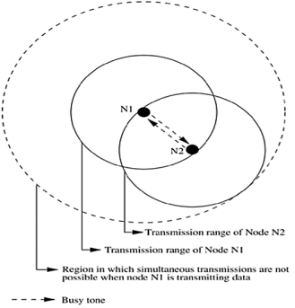
Figure. 12 Transmission in BTMA.
Dual Busy Tone Multiple Access Protocol The dual busy tone multiple access protocol (DBTMA) is an extension of the BTMA scheme. Here again, the transmission channel is divided into two: the data channel and the control channel. As in BTMA, the data channel is used for data packet transmissions. The control channel is used for control packet transmissions (RTS and CTS packets) and also for transmitting the busy tones. DBTMA uses two busy tones on the control channel, BTt and BTr . The BTt tone is used by the node to indicate that it is transmitting on the data channel. The BTr tone is turned on by a node when it is receiving data on the data channel. The two busy tone signals are two sine waves at different well-separated frequencies.
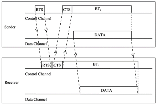
Figure 13 Packet Transmission in DBTMA
When compared to other RTS/CTS-based medium access control schemes (such as MACA and MACAW), DBTMA exhibits better network utilization. This is because the other schemes block both the forward and reverse transmissions on the data channel when they reserve the channel through their RTS or CTS packets. But in DBTMA, when a node is transmitting or receiving, only the reverse (receive) or forward (transmit) channels, respectively, are blocked. Hence the bandwidth utilization of DBTMA is nearly twice that of other RTS/CTS-based schemes.
MACA-By Invitation
MACA-by invitation (MACA-BI) is a receiver-initiated MAC protocol. It reduces the number of control packets used in the MACA protocol. MACA, which is a sender-initiated protocol, uses the three-way handshake mechanism, where first the RTS and CTS control packets are exchanged, followed by the actual DATA packet transmission. MACA-BI eliminates the need for the RTS packet. In MACA-BI the receiver node initiates data transmission by transmitting a ready to receive (RTR) control packet to the sender. If it is ready to transmit, the sender node responds by sending a DATA packet. Thus, data transmission in MACA-BI occurs through a two-way handshake mechanism.

Figure.14 Packet transmission in MACA-BI.
The receiver node may not have an exact knowledge about the traffic arrival rates at its neighboring sender nodes. It needs to estimate the average arrival rate of packets. For providing necessary information to the receiver node for this estimation, the DATA packets are modified to carry control information regarding the backlogged flows at the transmitter node, number of packets queued, and packet lengths.
However, the hidden terminal problem still affects the control packet transmissions. This leads to protocol failure, as in certain cases the RTR packets can collide with DATA packets. One such scenario is depicted in Figure below. Here, RTR packets transmitted by receiver nodes R1 and R2 collide at node A. So node A is not aware of the transmissions from nodes S1 and S2. When node A transmits RTR packets, they collide with DATA packets at receiver nodes R1 and R2.

Figure.15 Hidden terminal problem in MACA-BI.
- S1, S2 are sender nodes
- R1, R2 are receiver nodes
- Neighbour nodes
The efficiency of the MACA-BI scheme is mainly dependent on the ability of the receiver node to predict accurately the arrival rates of traffic at the sender nodes.
Contention-based protocols with reservation mechanisms
Protocols described in this section have certain mechanisms that aid the nodes in effecting bandwidth reservations. Though these protocols are contention-based, contention occurs only during the resource (bandwidth) reservation phase. Once the bandwidth is reserved, the node gets exclusive access to the reserved bandwidth. Hence, QoS support can be provided for real-time traffic.
Distributed Packet Reservation Multiple Access Protocol
The distributed packet reservation multiple access protocol (D-PRMA) extends the earlier centralized packet reservation multiple access (PRMA) scheme into a distributed scheme that can be used in ad hoc wireless networks. PRMA was proposed for voice support in a wireless LAN with a base station, where the base station serves as the fixed entity for the MAC operation. DPRMA extends this protocol for providing voice support in ad hoc wireless networks.
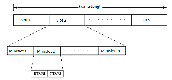
Figure 16 Frame structure in D-PRMA
In order to prioritize nodes transmitting voice traffic (voice nodes) over nodes transmitting normal data traffic (data nodes), two rules are followed in D-PRMA. According to the first rule, the voice nodes are allowed to start contending from minislot 1 with probability p = 1; data nodes can start contending only with probability p < 1. For the remaining (m - 1) minislots, both the voice nodes and the data nodes are allowed to contend with probability p < 1. This is because the reservation process for a voice node is triggered only after the arrival of voice traffic at the node; this avoids unnecessary reservation of slots.
Collision Avoidance Time Allocation Protocol
The collision avoidance time allocation protocol (CATA) is based on dynamic topology dependent transmission scheduling. Nodes contend for and reserve time slots by means of a distributed reservation and handshake mechanism. CATA supports broadcast, unicast, and multicast transmissions simultaneously. The operation of CATA is based on two basic principles:
- The receiver(s) of a flow must inform the potential source nodes about the reserved slot on which it is currently receiving packets. Similarly, the source node must inform the potential destination node(s) about interferences in the slot.
- Usage of negative acknowledgments for reservation requests, and control packet transmissions at the beginning of each slot, for distributing slot reservation information to senders of broadcast or multicast sessions.

Figure 17 Frame format in CATA.
Each node that receives data during the DMS of the current slot transmits a slot reservation (SR) packet during the CMS1 of the slot. This serves to inform other neighboring potential sender nodes about the currently active reservation. The SR packet is either received without error at the neighbor nodes or causes noise at those nodes, in both cases preventing such neighbor nodes from attempting to reserve the current slot.
Five-Phase Reservation Protocol (FPRP)
The five-phase reservation protocol (FPRP) is a single-channel time division multiple access (TDMA)-based broadcast scheduling protocol. Nodes use a contention mechanism in order to acquire time slots. The protocol is fully distributed, that is, multiple reservations can be simultaneously made throughout the network. Time is divided into frames. There are two types of frames: reservation frame (RF) and information frame (IF). Each RF is followed by a sequence of IFs. Each RF has N reservation slots (RS), and each IF has N information slots (IS). In order to reserve an IS, a node needs to contend during the corresponding RS. Based on these contentions, a TDMA schedule is generated in the RF and is used in the subsequent IFs until the next RF. The structure of the frames is shown in Figure. Each RS is composed of M reservation cycles (RC).
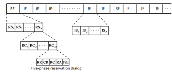
Figure.18 Frame structure in FPRP.
The protocol assumes the availability of global time at all nodes. Each node therefore knows when a five-phase cycle would start. The five phases of the reservation process are as follows:
- Reservation request phase: Nodes that need to transmit packets send reservation request (RR) packets to their destination nodes.
- Collision report phase: If a collision is detected by any node during the reservation request phase, then that node broadcasts a collision report (CR) packet. The corresponding source nodes, upon receiving the CR packet, take necessary action.
- Reservation confirmation phase: A source node is said to have won the contention for a slot if it does not receive any CR messages in the previous phase. In order to confirm the reservation request made in the reservation request phase, it sends a reservation confirmation (RC) message to the destination node in this phase.
- Reservation acknowledgment phase: In this phase, the destination node acknowledges reception of the RC by sending back a reservation acknowledgment (RA) message to the source. The hidden nodes that receive this message defer their transmissions during the reserved slot.
- Packing and elimination (P/E) phase: Two types of packets are transmitted during this phase: packing packet and elimination packet. The details regarding the use of these packets will be described later in this section.
Each of the above five phases is described below.
Reservation request phase: In this phase, each node that needs to transmit packets sends an RR packet to the intended destination node with a contention probability p, in order to reserve an IS. Such nodes that send RR packets are called requesting nodes (RN). Other nodes just keep listening during this phase.
Collision report phase: If any of the listening nodes detects collision of RR packets transmitted in the previous phase, it broadcasts a collision report (CR) packet. By listening for CR packets in this phase, an RN comes to know about collision of the RR packet it had sent. If no CR is heard by the RN in this phase, then it assumes that the RR packet did not collide in its neighborhood. It then becomes a transmitting node (TN). Reservation confirmation phase: An RN that does not receive any CR packet in the previous phase, that is, a TN, sends an RC packet to the destination node. Each neighbor node that receives this packet understands that the slot has been reserved, and defers its transmission during the corresponding information slots in the subsequent information frames until the next reservation frame.
Reservation acknowledgment phase: On receiving the RC packet, the intended receiver node responds by sending an RA packet back to the TN. This is used to inform the TN that the reservation has been established. In case the TN is isolated and is not connected to any other node in the network, then it would not receive the RA packet, and thus becomes aware of the fact that it is isolated.
Packing/elimination (P/E) phase: In this phase, a packing packet (PP) is sent by each node that is located within two hops from a TN, and that had made a reservation since the previous P/E phase. A node receiving a PP understands that there has been a recent success in slot reservation three hops away from it, and because of this some of its neighbors would have been blocked during this slot.
Contention-based MAC protocols with scheduling mechanisms
Protocols that fall under this category focus on packet scheduling at the nodes and transmission scheduling of the nodes. Scheduling decisions may take into consideration various factors such as delay targets of packets, laxities of packets, traffic load at nodes, and remaining battery power at nodes. In this section, some of the scheduling-based MAC protocols are described.
Distributed Priority Scheduling and Medium Access in Ad Hoc Networks This work presents two mechanisms for providing quality of service (QoS) support for connections in ad hoc wireless networks. The first technique, called distributed priority scheduling (DPS), piggy-backs the priority tag of a node's current and head-of-line packets on the control and data packets. By retrieving information from such packets transmitted in its neighborhood, a node builds a scheduling table from which it determines its rank (information regarding its position as per the priority of the packet to be transmitted next) compared to other nodes in its neighborhood.
Distributed Priority Scheduling The distributed priority scheduling scheme (DPS) is based on the IEEE 802.11 distributed coordination function. DPS uses the same basic RTS-CTS-DATA-ACK packet exchange mechanism. The RTS packet transmitted by a ready node carries the priority tag/priority index for the current DATA packet to be transmitted. The priority tag can be the delay target for the DATA packet. On receiving the RTS packet, the intended receiver node responds with a CTS packet. The receiver node copies the priority tag from the received RTS packet and piggybacks it along with the source node id, on the CTS packet. Neighbor nodes receiving the RTS or CTS packets (including the hidden nodes) retrieve the piggy-backed priority tag information and make a corresponding entry for the packet to be transmitted, in their scheduling tables (STs). Each node maintains an ST holding information about packets, which were originally piggy-backed on control and data packets.
Distributed Wireless Ordering Protocol The distributed wireless ordering protocol (DWOP) consists of a media access scheme along with a scheduling mechanism. It is based on the distributed priority scheduling scheme. DWOP ensures that packets access the medium according to the order specified by an ideal reference scheduler such as first-in-first-out (FIFO), virtual clock, or earliest deadline first. In this discussion, FIFO is chosen as the reference scheduler. In FIFO, packet priority indices are set to the arrival times of packets. Similar to DPS, control packets are used in DWOP to piggy-back priority information regarding head-of-line packets of nodes. As the targeted FIFO schedule would transmit packets in order of the arrival times, each node builds up a scheduling table (ST) ordered according to the overheard arrival times. The key concept in DWOP is that a node is made eligible to contend for the channel only if its locally queued packet has a smaller arrival time compared to all other arrival times in its ST(all other packets queued at its neighbor nodes), that is, only if the node finds that it holds the next region-wise packet in the hypothetical FIFO schedule.
References:
1. Cristopher Cox, “An Introduction to LTE: LTE, LTE-Advanced, SAE, VoLTE and 4G Mobile Communications”, Wiley, 2nd Edition.
2. E. Dahlman, J. Skold, and S. Parkvall, “4G, LTE-Advanced Pro and The Road to 5G”, Academic Press, 3rd Edition.
3. B. P. Lathi, “Modern Digital and Analog Communications Systems”. Oxford university press, 2015, 4th Edition.
4. Obaidat, P. Nicopolitids, “Modeling and simulation of computer networks and systems: Methodologies and applications” Elsevier, 1st Edition.