Unit - 1
Introduction To Computer Networks
The concept of a network is no stranger to the common person. It typically refers to an interconnected" configuration of individuals. Similarly, the term networking refers to communicating either
With or within a group. Among humans, wherever there is communication, there is a network. Examples are many, e.g., a network of neighbors (neighborhood watch), a network of intelligence (spy networks), a network of gossip among close friends, a news network, a broadcast network, a book club or giant social media platforms like Facebook, Twitter and Instagram.
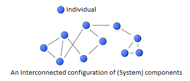
Computer networks play a key role in modern society. We done a computer network from two perspectives: physically (hardware) and logically (software and data).
Types of computer network
LOCAL AREA NETWORK (LAN)
Networks used to interconnect computers in a single room, rooms within a building or buildings on one site are called Local Area Network (LAN).
LAN transmits data with a speed of several megabits per second (106 bits per second). The transmission medium is normally coaxial cables.
LAN links computers, i.e., software and hardware, in the same area for the purpose of sharing information.
Usually, LAN links computers within a limited geographical area because they must be connected by a cable, which is quite expensive.
People working in LAN get more capabilities in data processing, work processing and other information exchange compared to stand-alone computers. Because of this information exchange, most of the business and government organizations are using LAN. Major Characteristics of LAN Every computer has the potential to communicate with any other computers of the network. High degree of interconnection between computers. Easy physical connection of computers in a network.
Inexpensive medium of data transmission. High data transmission rate.
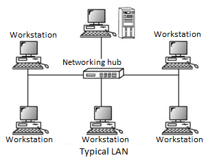
Components of LAN
Workstations
In LAN, a workstation refers to a machine that will allow users to access a LAN and its resources while providing intelligence on board allowing local execution of applications.
It may allow data to be stored locally or remotely on a file server.
Obviously, diskless workstations require all data to be stored remotely, including that data necessary for the diskless machine to boot up.
Executable files may reside locally or remotely as well, meaning a workstation can run its own programs or those copied off the LAN.
Servers
A server is a computer that provides the data, software and hardware resources that are shared on the LAN.
A LAN can have more than one server; each has its unique name on the network and all LAN users identify the server by its name.
Dedicated Server: A server that functions only as a storage area for data and software and allows access to hardware resources is called a dedicated server. Dedicated servers need to be powerful computers.
Non-Dedicated Server: In many LANs, the server is just another work station. Thus, there is a user networking on the computer and using it as a workstation, but part of the computer also doubles up as a server. Such a server is called a non-dedicated server. Since, it is not completely dedicated to serving. LANs do not require a dedicated server since resource sharing amongst a few workstations is proportionately on a smaller scale.
Other Types of Servers: In large installations, which have hundreds of workstations sharing resource, a single computer is often not sufficient to function as a server. Some of the other servers have been discussed here:
File Server: A file server stores files that workstations can access and it also decides on the rights and restrictions that the users need to have while accessing files on LAN.
Printer Server: A Printer server takes care of the printing requirement of number of workstations.
Modem Server: It allows LAN users to use the modem to transmit long distance messages. Server attached to one or two modems would serve the purpose.
Clients
A client is any machine that requires something from a server.
In the more common definition of a client, the server supplies files and sometimes processing power to the smaller machines connected to it.
Each machine is a client.
Thus, a typical ten PC local area network may have one large server with all the major files and databases on it and all the other machines connected as clients. This type of terminology is common with TCP/IP networks, where no single machine is necessarily the central repository.
Nodes
Small networks that comprise of a server and number of PCs.
Each PC on the network is called a node. A node essentially means any device that is attached to the network. Because each machine has a unique name or number (so the rest of the network can identify it), you will hear the term node name or node number quite often.
Network Interface Cards: The Network Interface card, or LAN adapter, functions as an interface between the computer and the network cabling, so it must serve two masters. Inside the computer, it controls the flow of data to and from the Random-Access Memory (RAM).
Outside the computer, it controls the flow of data in and out of the network cable system.
An interface card has a specialized port that matches the electrical signaling standards used on the cable and the specific type of cable connector. One must select a network interface card that matches your computer’s data bus and the network cable. Token ring LANs require token ring NICs, Ethernet LANs require Ethernet NICs, etc.
The peripheral component interface bus (PCI) has emerged as a new standard for adapter card interfaces. It is advisable to use bus PCI-equipped computers and PCI LAN adapters wherever possible.
Software is required to interface between a particular NIC and an operating system called as Network Interface Card Driver.
Connectors
Connectors used with TP included RJ-Il and RJ-45 modular connectors in current used by phone companies. Occasionally other special connectors, such as IBM’s Data Connector, are used. RJ-Il connectors accommodate 4 wires or 2 twisted pairs, while RJ-45 houses 8 wires or 4 twisted pairs.
The Network Operating System:
The Network Operating System software acts as the command center, enabling all of the network hardware and all other network software to function together as one cohesive, organized system.
In other words, the network operating system is the heart of the network.
It can be client-server or Peer-to-Peer Network Operating System.
Advantages of LAN
The reliability of network is high because the failure of one computer in the network does not affect the functioning for other computers. Addition of new computer to network is easy. High rate of data transmission is possible. Peripheral devices like magnetic disk and printer can be shared by other computers.
Uses of LAN
Followings are the major areas where LAN is normally used:
- File transfer and Access
- Word and text processing
- Electronic message handling
- Remote database access
- Personal computing
- Digital voice transmission and storage
- Office automation
- Factory automation
- Distributed Computing
- Process Control
WIDE AREA NETWORK (WAN)
The term Wide Area Network (WAN) is used to describe a computer network spanning a regional, national or global area.
For example, for a large company the headquarters might be at Delhi and regional branches at Mumbai, Chennai, Bengaluru and Kolkata.
Here regional centers are connected to headquarters through WAN.
The distance between computers connected to WAN is larger. Therefore, the transmission mediums used are normally telephone lines, microwaves and satellite links.
Characteristics of WAN
Following are the major characteristics of WAN. Communication Facility
For a big company spanning over different parts of the country, the employees can save long distance phone calls and it overcomes the time lag in overseas communications. Computer conferencing is another use of WAN where users communicate with each other through their computer system.
Remote Data Entry
Remote data entry is possible in WAN. It means sitting at any location you can enter data, update data and query other information of any computer attached to the WAN but located in other cities.
For example, suppose you are sitting at Chennai and want to see some data of a computer located at Delhi, you can do it through WAN.
Centralized Information
In modem computerized environment you will find that big organizations go for centralized data storage.
This means if the organization is spread over many cities, they keep their important business data in a single place.
As the data are generated at different sites, WAN permits collection of this data from different sites and save at a single site.
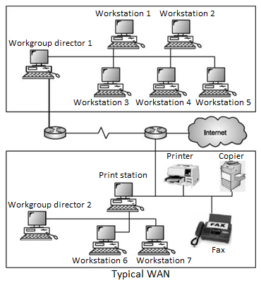
Difference between LAN and WAN
LAN is restricted to limited geographical area of few kilometers. But WAN covers great distance and operate nationwide or even worldwide.
In LAN, the computer terminals and peripheral devices are connected with wires and coaxial cables. In WAN there is no physical connection. Communication is done through telephone lines and satellite links.
Cost of data transmission in LAN is less because the transmission medium is owned by a single organization. In case of WAN the cost of data transmission is very high because the transmission mediums used are wired, either telephone lines or satellite links.
The speed of data transmission is much higher in LAN than in WAN. The transmission speed in LAN varies from 0.1 to 100 megabits per second. In case of WAN the speed ranges from 1800 to 9600 bits per second (bps). Few data transmission errors occur in LAN compared to WAN. It is because in LAN the distance covered is negligible.
METROPOLITAN AREA NETWORK (MAN)
A Metropolitan Area Network (MAN) is a bigger version of a Local Area Network (LAN) and usually uses similar technology. A MAN can cover a group of corporate offices or a town or city, and can be either privately or publicly owned. A MAN can support both data and voice, and may be related to the local cable television network (CATV). A MAN employs one or two cables, and does not contain switching elements, which simplifies the design. A standard has been adopted for MANs called Distributed Queue Dual Bus (DQDB) and is defined by IEEE 802.6.
DQDB consists of two unidirectional buses (cables) to which all of the computers on the network are connected.
Each bus has a head-end that initiates transmission activity.
In the following diagram, traffic that is intended for a computer to the right of the source computer uses the upper bus, while traffic intended for a computer to the left uses the lower bus.
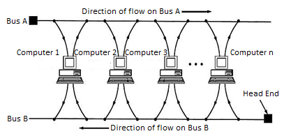
Fig: Typical MAN network (also known as 802.6 DQDB network)
The network is based on fiber-optic cable in a dual-bus topology, and traffic on each bus is unidirectional, providing a fault-tolerant configuration.
Bandwidth is allocated using time slots, and both synchronous and asynchronous modes are supported.
Comparison between LAN, Man, WAN
Basis of Comparison | LAN | MAN | WAN |
Expands to | Local Area Network | Metropolitan Area Network | Wide Area Network |
Meaning | A network that connects a group of computers in a small geographical area. | It covers relatively large region such as cities, towns. | It spans large locality and Connects countries together. Example Internet. |
Ownership of Network | Private | Private or Public | Private or Public |
Design and maintenance | Easy | Difficult | Difficult |
Propagation Delay | Short | Moderate | Long |
Speed | High | Moderate | Low |
Fault Tolerance | More Tolerant | Less Tolerant | Less Tolerant |
Congestion | Less | More | More |
Used for | College, School, Hospital. | Small towns, City. | Country/Continent. |
Wireless Network
To set up a wireless network, each wireless adapter must be configured for mode instead of infrastructure mode, which is the mode used in networks where there is a central device like a router or server that manages network traffic. In addition, all wireless adapters on the ad-hoc network must use the same Service Set Identifier, or SSID, and the same wireless channel number.
Wireless networks cannot bridge to wired LANs or to the internet without installing a special-purpose network gateway.
Networks make sense when needing to build a small, all wireless LAN quickly for a minimum amount of money spent on equipment.
Adhoc networks also work well as a temporary fallback mechanism if equipment for an infrastructure mode network, such as a router or access point, fails.
The rapidly expanding technology of cellular communication, wireless LANs, and satellite services will make information accessible anywhere and at any time. Regardless of size, most mobile computers will be equipped with a wireless connection to the fixed part of the network, and, perhaps, to other mobile computers. The resulting computing environment, which is often referred to as mobile or nomadic computing, no longer requires users to maintain a fixed and universally known position in the network and enables almost unrestricted mobility. Mobility and portability will create an entire new class of applications and, possibly, new massive markets combining personal computing and consumer electronics. Mobile Computing is an umbrella term used to describe technologies that enable people to access network services anyplace, anytime, and anywhere
A communication device can exhibit any one of the following characteristics:
Fixed and wired: This configuration describes the typical desktop computer in an office.
Neither weight nor power consumption of the devices allow for mobile usage. The devices use fixed networks for performance reasons.
Mobile and wired: Mobile /laptops fall into this category is used to carry the laptop from one hotel to the next, reconnecting to the network via the telephone network and a modem.
Fixed and wireless: This mode is used for installing networks, e.g., in historical buildings to avoid damage by installing wires, or at trade shows to ensure fast network setup.
Mobile and wireless: This is the most interesting case. No cable restricts the user, who can roam between different wireless networks.
A simplified reference model
The figure shows the protocol stack implemented in the system according to the reference model. End systems, such as the PDA and computer in the example, need a full protocol stack comprising the application layer, transport layer, network layer, data link layer, and physical layer.
Applications on the end systems communicate with each other using the lower layer services. Intermediate systems, such as the interworking unit, do not necessarily need all of the layers.
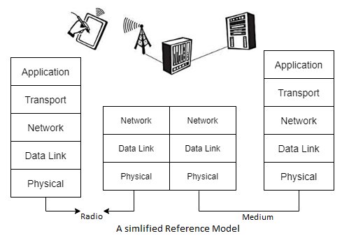
● Physical layer: This is the lowest layer in a communication system and is responsible for the conversion of a stream of bits into signals that can be transmitted on the sender side. The physical layer of the receiver then transforms the signals back into a bit stream. For wireless communication, the physical layer is responsible for frequency selection, generation of the carrier frequency, signal detection (although heavy interference may disturb the signal), modulation of data onto a carrier frequency and (depending on the transmission scheme) encryption.
● Data link layer: The main tasks of this layer include accessing the medium, multiplexing of different data streams, correction of transmission errors, and synchronization (i.e., detection of a data frame). Altogether, the data link layer is responsible for a reliable point to point connection between two devices or a point-to-multipoint connection between one sender and several receivers.
● Network layer: This third layer is responsible for routing packets through a network or establishing a connection between two entities over many other intermediate systems. Important functions are addressing, routing, device location, and handover between different networks.
● Transport layer: This layer is used in the reference model to establish an end-to-end connection
● Application layer: Finally, the applications (complemented by additional layers that can support applications) are situated on top of all transmission oriented layers. Functions are service location, support for multimedia applications, adaptive applications that can handle the large variations in transmission characteristics, and wireless access to the world-wide web using a portable device.
GSM: Mobile services, System architecture, Radio interface, Protocols, Localization and calling, Handover, Security, and New data services
GSM Architecture A GSM system consists of three subsystems, the radio sub system (RSS), the network and switching subsystem (NSS), and the operation subsystem (OSS).
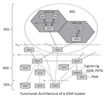
Network Switching Subsystem: The NSS is responsible for performing call processing and subscriber related functions. The switching system includes the following functional units:
Home location register (HLR): It is a database used for storage and management of subscriptions. HLR stores permanent data about subscribers, including a subscriber’s service profile, location information and activity status. When an individual buys a subscription from the PCS provider, he or she is registered in the HLR of that operator.
Visitor location register (VLR): It is a database that contains temporary information about subscribers that is needed by the MSC in order to service visiting subscribers. VLR is always integrated with the MSC. When a MS roams into a new MSC area, the VLR connected to that MSC will request data about the mobile station from the HLR. Later if the mobile station needs to make a call, VLR will be having all the information needed for call setup.
Authentication center (AUC): A unit called the AUC provides authentication and encryption parameters that verify the user’s identity and ensure the confidentiality of each call.
Equipment identity register (EIR): It is a database that contains information about the identity of mobile equipment that prevents calls from stolen, unauthorized or defective mobile stations.
Mobile switching center (MSC): The MSC performs the telephony switching functions of the system. It controls calls to and from other telephone and data systems.
Introduction to SDN
Software Defined Networks (SDN, also known as network virtualization) are changing what networks are, do, and how you deal with them.
SDN’s different approach, most notably centralizing many of the network control functions, deeply changes - and simplifies - how you interact with your network, particularly for network and service configuration.
The centralization of the control functions also leads to simpler, less-costly switching elements, even to the extent of offering the potential for commoditized switches.
The industry is already witnessing the rapid take up of SDN in the data center, where the shortcomings of conventional networks are most problematic.
Drawbacks Of Existing Network
• Difficult to perform real world experiments on large scale production networks
1>Research stagnation requires costly equipment to be procured and networks to be setup by each team for research
2> Networks have remained the same for many years
3> Rate of innovation in networks is slower because of lack of high-level abstraction
• Closed Systems
1>They are hard to collaborate meaningfully
2>The vendors are starting to open-up but not meaningfully
• Network Equipment in recent decades
1>Hardware centric
2>Based on custom programming
Limitation in extension to network capacity
Need of faster packet switching capability
Impact of these are slower Innovation and Reduced flexibility once chips are fabricated
Proprietary networking devices with proprietary software and hardware
1>Innovation is limited to vendor/ vendor partners
2>Huge barriers for new ideas in networking
SDN Principles
It has Separate Control plane and Data plane entities
It Execute or run Control plane software on general purpose hardware
Decouple from specific networking hardware and Use commodity servers
It is having programmable data planes
(a) Maintain, control and program data plane are isolated from a central entity
• The architecture to control is not just a networking device but an entire network.
Need for SDN
Facilitate Innovation in Network
Layered architecture with Standard Open Interfaces
Independent innovation at each layer
Experiment and research using non-bulky, non-expensive equipment
More accessibility since software can be easily developed by more vendors
Speed to market no hardware fabrication cycles
More flexibility with programmability
Ease of customization and integration with other software
Ease of network configuration applications.
Fast upgrades for programming a network.
Protocol Fundamentals
In computing, a protocol is a set of rules which is used by computers to communicate with each other across a network.
A protocol is a convention or standard that controls or enables the connection, communication, and data transfer between computing endpoints. In its simplest form, a protocol can be defined as the rules governing the syntax, semantics, and synchronization of communication.
Protocols may be implemented by hardware, software, or a combination of the two. At the lowest level, a protocol defines the behavior of a hardware connection.
Typical Properties
Detection of the underlying physical connection (wired or wireless), or the existence of the other endpoint or node:
Handshaking.
Negotiation of various connection characteristics.
How to start and end a message.
Procedures on formatting a message.
What to do with corrupted or improperly formatted messages (error correction).
How to detect unexpected loss of the connection, and what to do next.
Termination of the session and/or connection.
Importance of Protocols
The protocols in human communication are separate rules about appearance, speaking, listening and understanding.
All these rules, also called protocols of conversation, represent different layers of communication.
They work together to help people successfully communicate. The need for protocols also applies to network devices. Computers have no way of learning.
Terms and Definitions
Protocol: Protocol is agreement between the communication - communicating parties on how communication is to proceed.
OR
Protocol: Protocol is strict procedure and sequence of actions to be followed in order to achieve orderly exchange of information among peer entities.
OR
Protocol: Protocol is a set of rules governing the format and meaning of the frames, packets or messages that are exchanged by the peer entities within a layer.
Protocol Stack: A list of protocols used by a certain system, one protocol per layer is called a protocol stack.
Interface: Between each pair of adjacent layers, there is an interface. The interface defines which primitive operations and services the lower layers offer to the upper one.
Network Architecture: A set of layers and protocols is called as network architecture.
Service: Services and protocols are distinct concepts although they are frequently confused.
Service is a set of primitives (operations) that a layer provides to the layer above it.
The service defines what operations the layer is prepared to perform on behalf of its users, but it says nothing at all about how these operations are implemented.
A service relates to an interface between two layers, with the lower layer being the service provider and the upper layer being the service user.
The following are the design issues for the layers:
Reliability: It is a design issue of making a network that operates correctly even when it is made up of unreliable components.
Addressing: There are multiple processes running on one machine. Every layer needs a mechanism to identify senders and receivers.
Error Control: It is an important issue because physical communication circuits are not perfect. Many errors detecting and error correcting codes are available. Both sending and receiving ends must agree to use any one code.
Flow Control: If there is a fast sender at one end sending data to a slow receiver, then there must be flow control mechanism to control the loss of data by slow receivers. There are several mechanisms used for flow control such as increasing buffer size at receivers, slow down the fast sender, and so on. Some process will not be in position to accept arbitrarily long messages. This property leads to mechanisms for disassembling, transmitting and the reassembling messages.
Multiplexing and De-multiplexing: If the data has to be transmitted on transmission media separately, it is inconvenient or expensive to setup separate connection for each pair of communicating processes. So, multiplexing is needed in the physical layer at sender end and de-multiplexing is need at the receiver end.
Scalability: When network gets large, new problem arises. Thus, scalability is important so that network can continue to work well when it gets large.
Routing: When there are multiple paths between source and destination, only one route must be chosen. This decision is made on the basis of several routing algorithms, which chooses optimized route to the destination.
Confidentiality and Integrity: Network security is the most important factor. Mechanisms that provide confidentiality defend against threats like eavesdropping. Mechanisms for integrity prevent faulty changes to messages.
Open System Interconnection Model (OSI) Reference Model
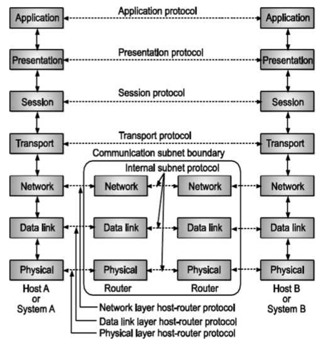
Fig: OSI MODEL
This model is based on a proposal developed by the International Standards Organization (ISO) as a first step towards International Standardization of Protocols used in various layers. This model is called as ISO-OSI (Open Systems Interconnection) reference model because it deals with connecting open systems that is systems that are open for communication with other systems. OSI model has seven layers. The OSI model defines a layered architecture as pictured. The protocols defined in each layer are responsible for following:
Communicating with the same peer protocol layer running in the opposite computer. Providing services to the layer above it (except for the top-level application layer). Peer layer communication provides a way for each layer to exchange messages or other data.
Characteristics of the OSI Layers
The seven layers of the OSI reference model can be divided into two categories: upper layers and lower layers.
The upper layers of the OSI model deal with application issues and generally are implemented only in software.
The highest layer, the application layer, is closest to the end user. Both users and application layer processes interact with software applications that contain a communication component.
The term upper layer is sometimes used to refer to any layer above another layer in the OSI model.
The lower layers of the OSI model handle data transport issues. The physical layer and the data link layer are implemented in hardware and software.
The lowest layer, the physical layer, is closest to the physical network medium (the network cabling, for example) and is responsible for actually placing information on the medium.
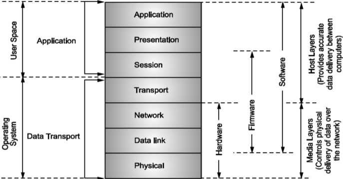
Fig: Illustrates the division between the upper and lower OSI layers
OSI Layers in Detail
The following is a description of just what each layer does:
Physical Layer: The Physical layer provides the electrical and mechanical interface to the network medium (the cable). This layer gives the data-link layer (layer 2) its ability to transport a stream of serial data bits between two communicating systems. It conveys the bits that move along the cable. It is responsible for making sure that the raw bits get from one place to another, no matter what shape they are in, and deals with the mechanical and electrical characteristics of the cable.
Data-Link Layer: The Data-Link layer handles the physical transfer, framing (the assembly of data into a single unit or block), flow control and error-control functions (and retransmission in the event of an error) over a single transmission link; it is responsible for getting the data packaged and onto the network cable. The data link layer provides the network layer (layer 3) reliable information-transfer capabilities. The data-link layer is often subdivided into two parts - Logical Link Control (LLC) and Medium Access Control (MAC) depending on the implementation.
Network Layer: The Network layer establishes, maintains, and terminates logical and/or physical connections. The network layer is responsible for translating logical addresses or names into physical addresses. It provides network routing and flow control functions across the computer-network interface.
Transport Layer: The Transport layer ensures that data is successfully sent and received between the two computers. If data is sent incorrectly, this layer has the responsibility to ask for retransmission of the data. Specifically, it provides a network-independent, reliable message-independent, reliable message-interchange service to the top three application-oriented layers. This layer acts as an interface between the bottom and top three layers. By providing the session layer (layer 5) with a reliable message-transfer service, it hides the detailed operation of the underlying network from the session layer.
Session Layer: The Session layer decides when to turn communication on and off between two computers - it provides the mechanism that controls the data-exchange process and co-ordinates the interaction between them. It sets up and clears communication channels between two communicating components. Unlike the network layer (layer 3), it deals with the programs running in each machine to establish conversations between them.
Presentation Layer: The Presentation layer performs code conversion and data reformatting (syntax translation). It is the translator of the network, making sure that the data is in the correct form for the receiving application. Of course, both the sending and receiving applications must be able to use data subscribing to one of the available abstract data syntax forms.
Application Layer: The Application layer provides the user interface between the software running in the computer and the network. It provides functions to the user’s software, including file transfer access, management and electronic mail.
Thus, the OSI, or Open Systems Interconnection, model defines a networking frame-work for implementing protocols in seven layers
Introduction to TCP/IP
TCP/IP is a suite of protocols, also known as the Internet Protocol Suite. It should not be confused with the OSI reference model, although elements of TCP/IP exist in OST The Transmission Control Protocol and the Internet Protocol are fundamental to the suite, hence the TCP/IP title.
TCP/IP is a set of protocols developed to allow co-operating computers to share resources across a network.
A community of researchers centered around the ARPANET developed this TCP/IP. The Internet protocol suite is the set of communication protocols that implement the protocol stack on which the internet and most commercial networks run.
The internet protocol suite like many protocol suites can be viewed as a set of layers, each layer solves a set of problems involving the transmission of data, and provides a well-defined service to the upper layer protocols based on using services from some lower layers.
Upper layers are logically closer to the user and deal with more abstract data, relying on lower layer protocols to translate data into forms that can eventually be physically transmitted.
The Transmission Control Protocol Internet Protocol (TCP/IP) protocol suite is the engine for the Internet and networks worldwide.
Its simplicity and power have led to it becoming the single network protocol of choice in the world today. In this chapter, we give an overview of the TCP/IP protocol suite.
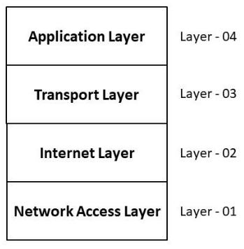
Fig. Typical four-layer TCP/IP model
Comparison between OSI & TCP/IP MODEL
Application Layer (7) |
| Application Layer |
Presentation Layer (6) | ||
Session Layer (5) | ||
Transport Layer (4) | Transport Layer | |
Network Layer (3) | Network Layer | |
Data Link Layer (2) | Layer 1 and Layer 2 | |
Physical Layer (1)
Physical Layer (1) |
Network Topology
The way, in which the connections are made, is called the topology of the network. Network topology specifically refers to the physical layout of the network, especially the locations of computers and how the cable is run between them. It is important to select the right topology.
Each topology has its own strengths and weaknesses.
The four most common topologies are
(i) Bus (ii) Star (iii) Ring (iv) Mesh
Bus Topology
Bus topology is often used when network installation is small.

Fig. Bus topology
Advantages
Simple and reliable in very small network, easy to use and understand.
Least amount of cable required to connect computers, so it is less expensive.
Extension of bus is easy by joining cable and using BNC connector. So, more computers can be connected.
A repeater can also be used to extend a bus, boost the signal and allow it to travel a longer distance.
Disadvantages
Heavy traffic (network traffic) can slow a bus considerably, because any computer can transmit data any time, uses entire B.W. And interrupts each other instead of communicating.
Each barrel connector weakens the signal power. It is difficult to troubleshoot bus. A cable break or loose connector will also cause reflections and bring down the whole network and network activity stops.
Star Topology
Star networks are used in concentrated networks, where the end-points are directly reachable from a central location. When network expansion is expected and when the greater reliability is needed, Hub may be used.
Advantages
It is very easy to modify and add new network without disturbing the rest of the network.
Center of a star network is good place to diagnose network faults.
Single computer failure does not bring down the whole network.
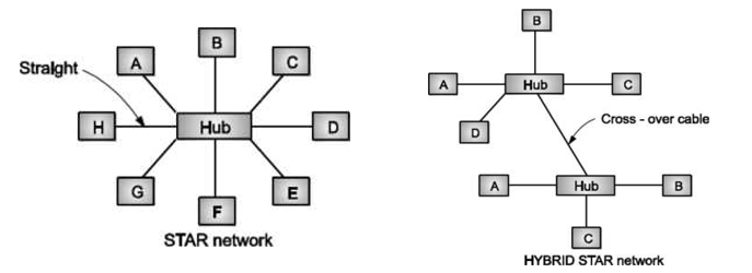
Fig: Star Topology
With hub, you can use several cable types - UTP, STP, coaxial, fiber, etc.
Disadvantages
If central hub fails, the whole network fails to operate.
Cost is more than bus network because network cables must be pulled to one central point. Thus, cable requirement increases.
Ring Topology
In ring network, each computer is connected to the next computer, with the last one connected to first. Messages flow around the ring in one direction. Since each computer retransmits what it receives, signal loss problems are there. There is no termination because there is no end to ring.
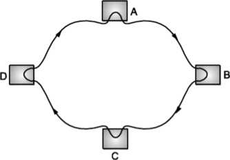
Fig: Ring Topology
Advantage:
When more users are added, system slows but doesn't fail.
Disadvantages:
Failure of one computer on the ring can affect the whole network.
It is difficult to troubleshoot ring network.
Adding or removing computers disturbs the entire network
Mesh Topology
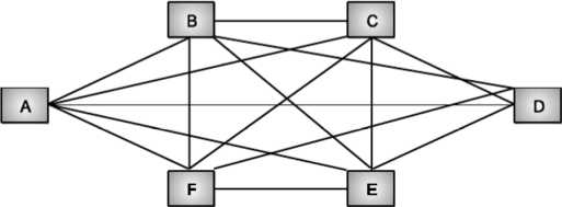
Fig: Mesh Topology
Each computer is connected to other with separate cable.
Advantages
• Guaranteed communication.
• High channel capacity.
Disadvantages
- Difficulty of installation and reconfiguration.
- Maintenance cost.
Hierarchical Topology
A network that is based upon the physical hierarchical topology must have at least three levels in the hierarchy of the tree, since a network with a central 'root' node and only one hierarchical level below it would exhibit the physical topology of a star.
A network that is based upon the physical hierarchical topology and with a branching factor of 1 would be classified as a physical linear topology.
The total number of point-to-point links in a network that is based upon the physical hierarchical topology will be one less that the total number of nodes in the network. If the nodes in a network that is based upon the physical hierarchical topology are required to perform any processing upon the data that is transmitted between nodes in the network, the nodes that are at higher levels in the hierarchy will be required to perform more processing operations on behalf of other nodes than the nodes that are lower in the hierarchy.
It is an extension of Star and bus Topologies, so in networks where these topologies can't be implemented individually for reasons related to scalability, tree topology is the best alternative.
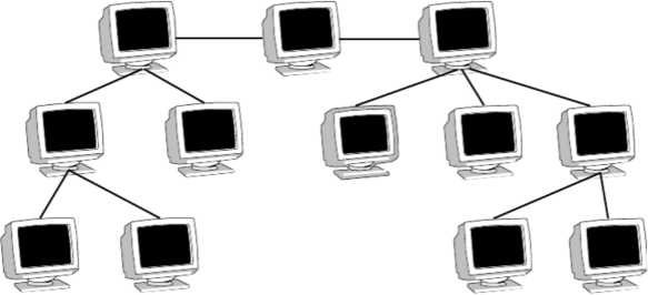
Fig: Hierarchical Topology
Expansion of Network is possible and easy. Here, we divide the whole network into segments (star networks), which can be easily managed and maintained. Error detection and correction is easy.
Each segment is provided with dedicated point-to-point wiring to the central hub. If one segment is damaged, other segments are not affected.
Advantages Of Hierarchical Topology
Because of its basic structure, tree topology, relies heavily on the main bus cable, if it breaks whole network is crippled. As more and more nodes and segments are added, the maintenance becomes difficult.
Scalability of the network depends on the type of cable used.
Disadvantages Of Hierarchical Topology
Comparison of Network Topologies A bus network is the least expensive way to install a network you do not have to purchase concentrators.
Design issues for layers.
Types of Transmission Medium
CAT5 (also, "CAT 5" or "Category 5") is an Ethernet network cable standard defined by the Electronic Industries Association and Telecommunications Industry Association (commonly known as EIA∕TIA). CAT5 cables use the fifth generation of twisted pair Ethernet technology and, since their inception in the 1990s, became the most popular of all twisted pair cable types.
Category-5 wiring layout
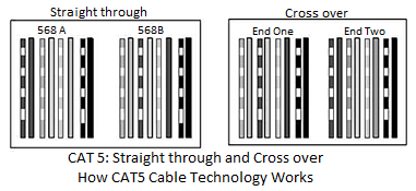
CAT5 cables contain four pairs of copper wire supporting Fast Ethernet speeds (up to 100 Mbps). As with all other types of twisted pair EIA∕TIA cabling, CAT5 cable runs are limited to a maximum recommended run length of 100 meters (328 feet). Although CAT5 cable usually contains four pairs of copper wire, Fast Ethernet communications only utilize two pairs. The EIA∕TIA published a newer Category 5 cable specification in 2001 called CAT5e ("CAT 5e" or CAT5 enhanced) designed to better support Gigabit Ethernet speeds (up to 1000 Mbps) by utilizing all four wire pairs. CAT5e cables additionally preserve backward compatibility with Fast Ethernet equipment.
While not technically rated to support Gigabit Ethernet, CAT5 cables are capable of supporting gigabit speeds at shorter distances. The wire pairs in CAT5 cables are not twisted as tightly as those constructed to CAT5e standards and thus have a higher risk of signal interference than increases with distance.
Types of CAT5 Cables
Twisted pair cable like CAT5 comes in two main varieties, solid and stranded.
Solid CAT5 cable supports longer length runs and works best in fixed wiring configurations like office buildings. Stranded CAT5 cable, on the other hand, is more pliable and better suited for shorter distance, movable cabling such as patch cables.
Although newer cable technologies like CAT6 and CAT7 have subsequently been developed, Category 5 Ethernet cable remains the popular choice for most wired local area networks (LANs), because or the combination of affordability and high performance that Ethernet gear offers.
Buying and Making CAT5 Cables
CAT5 Ethernet cables can be readily found in stores that sell electronic goods including online outlets. Pre-made cables come in standard lengths, such as 3, 5, 10 and 25 feet in the U.S.
The average consumer will be more than happy to buy their CAT5 cables pre-made from a shopping outlet, but some enthusiast makers and IT technicians also want to know how to build their own. At a minimum, this allows a person to create cables of exactly the length they need. The process is not too difficult to follow with a good understanding of the color-coded wiring scheme and a crimping tool.
Challenges with Category 5
Gigabit Ethernet already support the most local networks need, making it difficult to justify upgrades to CAT6 and newer standards.
With the emergence of wireless networking technologies, some industry investment has shifted from developing wired Ethernet over to wireless standards.
CATEGORY (CAT 6)
Category 6 (CAT6) is an Ethernet cable standard defined by the Electronic Industries Association and Telecommunications Industry Association (commonly known as EIA∕TIA). CAT6 is the sixth generation of twisted pair Ethernet cabling.
How CAT6 Cable Works
Category 6 was designed to support Gigabit Ethernet data rates (1 gigabit per second - Gbps). It additionally can support 10 Gigabit Ethernet connections over a limited distance (technically, 50 meters or 164 feet for a single cable).
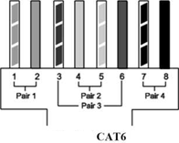
CAT6 cable contains four pairs of copper wire and utilizes all of these pairs for signaling in order to obtain the higher level of performance.
Other basic facts about CAT6 cables. Ends of a CAT6 cable use the same RJ-45 standard connector as previous generations of Ethernet cables.
Printing along the length of the cable sheath identifies it as "CAT6."
An enhanced version of CAT6 called CAT6a supports up to 10 Gbps speeds.
CAT6 vs. CAT6A
The Category 6 Augmented (CAT6A) cable standard was created to further improve on the performance of CAT6 for Ethernet cables. Using CAT6A enables 10 Gigabit Ethernet data rates over a single cable run up to 100 meters (328 feet), twice as far as CAT6, which supports 10 Gigabit Ethernet also, but only over distances up to 50 meters (164 feet). In return for the higher performance, CAT6A cables tend to cost noticeably more than their CAT6 counterparts, and they are slightly thicker (but still use standard RJ-45 connectors).
CAT6 vs. CAT5e
The history of cable design for Ethernet networks resulted in two separate efforts to improve on the previous generation Category 5 (CAT5) cable standard. One eventually became CAT6. The other, called Category 5 enhanced (CAT5e), was standardized earlier. CAT5e lacks some of the technical improvements that went into CAT6 but also supports Gigabit Ethernet installations, and at a lower cost.
Like CAT6, CAT5e utilizes a four-wire pair signaling scheme to achieve the necessary data rates. (In contrast, CAT5 cables contain four wire pairs but keep two of the pairs dormant.)
Because it became available in the market sooner and offered "good enough" performance for Gigabit Ethernet at a more affordable price point, CAT5e became a very popular choice for wired Ethernet installations. This plus the relatively slow transition of the industry to 10 Gigabit Ethernet has significantly slowed the adoption of CAT6.
Limitations of CAT6
As with all other types of twisted pair EIA∕TIA cabling, individual CAT6 cable runs are limited to a maximum recommended length of 100 meters (328 feet) for their nominal connection speeds (Gigabit Ethernet). As mentioned above, CAT6 supports 10 Gigabit Ethernet connections also but not at this full distance.
CAT6 costs more than CAT5e. Many buyers choose CAT5e over CAT6 for this reason, at the risk that they will need to upgrade cables again the future for better 10 Gigabit support.
Client -Server Architecture
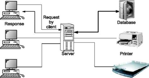
In a client/server network, a number of network clients or workstations request resources or services from the network. One or more network servers manage and provide these resources or services. The clients are computers that depend on the server for data and software. Network servers are also referred to as computer servers, or simply servers. Sometimes a server is described in terms of the specific service it provides, such as e- mail server, print server or storage server. Some servers, however, can provide all these services.
Servers are typically computers with more processing speed, memory and hard disk space than a regular desktop computer. The network servers run their own operating system that manages the various network tasks as well as services that run on the network. Depending on the need for network storage and services, a single network may only use one or a large number of servers.
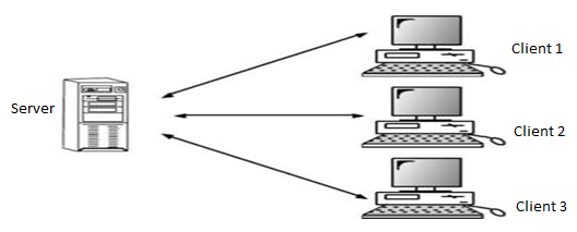
Clients are hardware devices which provide end users with access to data and services on the server. You can use these devices more or less independently. For example, you can open up software applications, create and edit documents and save files on the local storage medium, such as a hard disk. However, in a typical client/server network, a number of essential tasks are not performed by the client alone. Some typical examples are:
- A printer is connected to the network to print a document, the client sends a print request to the server.
- All the e-mail messages are stored on the server - the client is used to view and manage the messages but does not store the actual files.
- Very large databases are stored on the server the client accesses these without copying them onto the local hard drive.
Peer To Peer
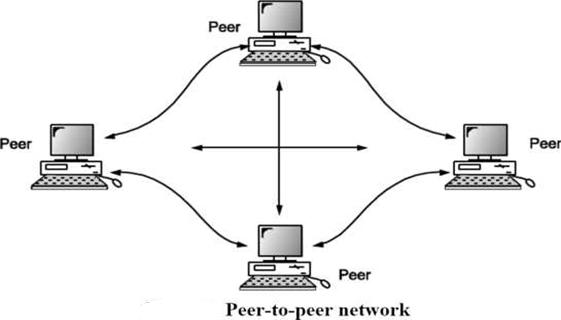
In a peer-to-peer or P2P network, the tasks are allocated among all the members of the network. There is no real hierarchy among the computers, and all of them are considered equal. This is also referred to as a distributed architecture or workgroup without hierarchy. A peer-to-peer network does not use a central computer server that controls network activity. Instead, every computer on the network has a special software running that allows for communications between all the computers.
Peer-to-peer is mostly used for file sharing. Here is how file sharing works: One computer user makes some of the files on the hard disk drive available for sharing. Information on these files is made available to the rest of the users so they can decide if they want to download one or more of these files. Once a second user has downloaded a file, this can also be made available to the rest of the users. So now there are two possible sources from which to download the same file. This is how files can be spread over thousands of users, one download at time.
One of the earliest peer-to-peer file sharing networks was Napster. One of the more recent protocols for sharing files is Bit Torrent. This protocol is used by the many users who provide links to their files on websites, such as The Pirate Bay.
A peer-to-peer network is robust in the sense that if one or several of the individual computers stop working for some reason, the network continues to function. On the other hand, the quality of the network depends completely on the contribution of individual participants. For example, in the case of file sharing, if very few people make their files available, there is very little for users to download.
While there are a number of different applications of peer-to-peer network architecture, file sharing is by far the most popular. This also includes file sharing networks that distribute copyrighted material, such as movies, music and books, without permission. This is against the law in most jurisdictions. Since peer-to-peer networks lack a central control system, such file sharing systems present a serious challenge to agencies trying to prevent this type of sharing.
Bridge
A bridge operates at data link layer. A bridge is a repeater, with add on functionality of filtering content by reading the MAC addresses of source and destination. It is also used for interconnecting two LANs working on the same protocol. It has a single input and single output port, thus making it a 2-port device.
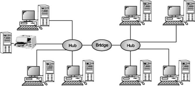
Fig: Bridge
Switch
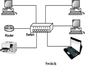
A switch is a multi port bridge with a buffer and a design that can boost its efficiency (large number of ports imply less traffic) and performance. Switch is data link layer device. Switch can perform error checking before forwarding data, that makes it very efficient as it does not forward packets that have errors and forward good packets selectively to correct port only. In other words, switch divides collision domain of hosts, but broadcast domain remains same.
Routers
A router is a device like a switch that routes data packets based on their IP addresses. Router is mainly a Network Layer device. Routers normally connect LANs and WANs together and have a dynamically updating routing table based on which they make decisions on routing the data packets. Router divide broadcast domains of hosts connected through it.
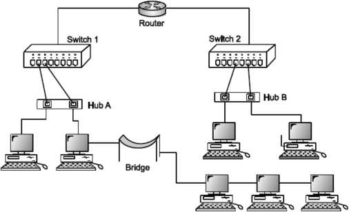
Fig. Routers
Router is mainly used to share internet connection wirelessly to other Wi-Fi enabled Laptops/Pc’s. Router cannot be used as bridge network between those PCs ∕ Computers, we cannot share files to other computer which are connected to same router.
Access Point
In a wireless local area network (WLAN), an access point is a station that transmits and receives data (sometimes referred to as a transceiver). An access point connects users to other users within the network and also can serve as the point of interconnection between the WLAN and a fixed wire network. Each access point can serve multiple users within a defined network area; as people move beyond the range of one access point, they are automatically handed over to the next one.

Gateway
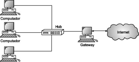
A gateway, as the name suggests, is a passage to connect two networks together that may work upon different networking models. They basically work as the messenger agents that take data from one system, interpret it, and transfer it to another system. Gateways are also called protocol converters and can operate at any network layer. Gateways are generally more complex than switch or router
Manchester Encoding
Manchester encoding (first published in 1949) is a synchronous clock encoding technique used by the physical layer to encode the clock and data of a synchronous bit stream. In this technique, the actual binary data to be transmitted over the cable are not sent as a sequence of logic Γs and O's (known technically as Non-Return to Zero (NRZ)). Instead, the bits are translated into a slightly different format that has a number of advantages over using straight binary encoding (i.e., NRZ).
In the Manchester encoding shown, a logic O is indicated by a O to 1 transition at the centre of the bit and a logic 1 is indicated by a 1 to O transition at the centre of the bit. Note that signal transitions do not always occur at the ‘bit boundaries’ (the division between one bit and another), but that there is always a transition at the centre of each bit. The Manchester encoding rules are summarized below:
Table:
Original Data | Value Sent |
Logic 0 | 0 to 1 (upward transition at bit centre) |
Logic 1 | 1 to 0 (downward transition at bit centre) |
Note that in some cases you will see the encoding reversed, with O being represented as a O to 1 transition. The two definitions have co-existed for many years. The Ethernet Blue-Book and IEEE standards (10 Mbps) describe the method in which a Logic O is sent as O to 1 transition, and a Logic 1 as a one to zero transition (where a zero is represented by a less negative voltage on the cable).
The following diagram shows a typical Manchester encoded signal with the corresponding binary representation of the data (1,1,0,1,0,0) being sent

Note that signal transitions do not always occur at the 'bit boundaries' (the division between one bit and another), but that there is always a transition at the centre of each bit. The encoding may be alternatively viewed as a phase encoding where each bit is encoded by a positive 90-degree phase transition, or a negative 90-degree phase transition. The Manchester code is therefore sometimes known as a Biphase Code.
A Manchester encoded signal contains frequent level transitions which allow the receiver to extract the clock signal using a Digital Phase Locked Loop (DPLL) and correctly decode the value and timing of each bit. To allow reliable operation using a DPLL, the transmitted bit stream must contain a high density of bit transitions. Manchester encoding ensures this, allowing the receiving DPLL to correctly extract the clock signal.
The bi-phase Manchester encoding can consume up to approximately twice the bandwidth of the original signal (20 MHz). This is the penalty for introducing frequent transitions.
For a 10 Mbps LAN, the signal spectrum lies between the 5 and 20 MHz. Manchester encoding is used as the physical layer of an Ethernet LAN, where the additional bandwidth is not a significant issue for coaxial cable transmission, the limited bandwidth of CAT5e cable necessitated a more efficient encoding method for 100 Mbps transmission using a 4b∕5b MLT code.
This uses three signal levels (instead of the two levels used in Manchester encoding) and therefore allows a 100 Mbps signal to occupy only 31 MHz of bandwidth. Gigabit Ethernet utilizes five levels and 8b∕10b encoding, to provide even more efficient use of the limited cable bandwidth, sending 1 Gbps within 100 MHz of bandwidth.
Example of Manchester Encoding
The pattern of bits ”01111001” encodes to “01 10 10 10 10 01 01 10”.
Another more curious example is the pattern “1 0 1 0 1 etc” which encodes to “10 01 10 01 10” which could also be viewed as “1 00 11 00 11 0 Thus for a 10 Mbps Ethernet LAN, the preamble sequence encodes to a 5 MHz square wave! (i.e., One half cycle in each 0.1 microsecond bit period.)
The Differential Manchester Coding
The Differential Manchester Code is a variation of the Manchester code. Following examples describes the differential Manchester coding.
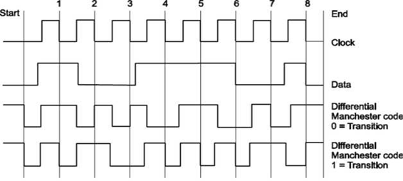
Like before, the transmission line is kept HIGH when no data is sent (before Start and after End). There are 2 encoding methods: The first is the "Transition on LOW" and the second is the "Transition on HIGH". Both methods work exactly the same. For this example, I am going to use the first method, "Transition on LOW".
Here is how it goes. In the middle of each clock pulse, a transition occurs, regardless of the bit that was sent or is about to be sent. A data bit is sent during each negative clock transition. If the data bit is 0, then a polarity transition occurs (if was HIGH it goes LOW, and if it was LOW it goes HIGH), otherwise the line remains unchanged.
In above example, the data that is transmitted is the binary '10011101' (starting from left to right). Each data bit is transmitted during negative transition of the clock. I have marked these clock transitions with red lines (except the first and last lines which indicate the start and stop of the transition). Between each bit transmission, the code line changes polarity.
This is done to help the receiver recreate the clock signal and synchronize with the transmitter. As I said before, I will use the "Transition on LOW" method. This means that when a bit is transmitted, if this bit is ZERO the data line changes polarity. Otherwise, if the bit is 1 the data line polarity remains unchanged.
Suppose now that we want to transmit this byte (10011101). The code line is HIGH. The transmission is initiated by pulling the code line LOW. After half a pulse, the output is pulled HIGH.
This is part of the synchronization transition that occurs every middle of a bit transmission. Half a pulse next, the first bit is transmitted.
The first bit is 1 (starting from left), so the code line polarity remains unchanged. After half a pulse, the code line polarity changes state and goes LOW.
After one full pulse, the second bit is about to be transmitted. This bit is the 0, so the code line changes polarity and goes HIGH. The same algorithm is used to transmit all 8 bits of the data. Finally, the code line is pulled HIGH and the transmission ends.
The major difference between the Differential Manchester Code, is that the receiver does not need to know the polarity of the signal. The polarity can be figured from the line transitions. In the above example, and NOT from the code line polarity.
This is something that makes this method kind a difficult to understand. It does not matter whether a logical 1 or 0 is received, but only whether the polarity is the same or is different from the previous value.
FHSS (frequency Hopping Spread Spectrum)
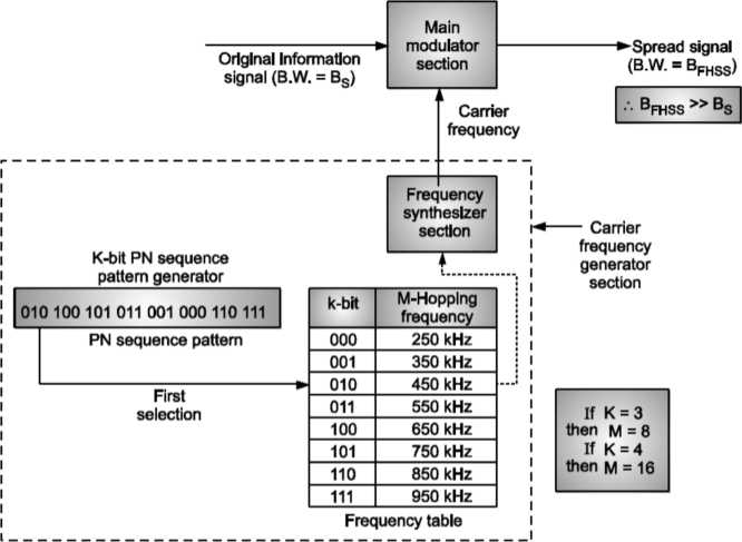
In FHSS ‘M’ are used for different carrier frequencies that are modulated by the input modulating signal or source information signal
Here at one moment original information signal modulates one carrier frequency, generated by PN sequence, frequency table and frequency synthesizer section. At the next moment the original information signal generates another carrier frequency as shown.
Modulation is done by using only one carrier frequency at a time in the FHSS system.PN sequence generator generates k-bit pattern for every hopping period Th For every K-bit, M-hopping frequencies are generated.
Also note that PN sequence pattern repeats after eight hoppings if K = 3 and M = 8.
PN sequence pattern will repeat after sixteen hoppings if K = 4 and M = 16
Direct Sequence Spread Spectrum (DSSS)
In DSSS technique also, the signal is spread but the process is different.
In DSSS each data bit is replaced with ‘n’ bits using a PN sequence code (or spreading code).
Or we can say that each bit is assigned a code of n bits, called as chips.
If Chip rate = Cr, Data rate = Dr then Cr = ∩Dr
In this technique, the PN sequence is applied directly to data entering the carrier modulator.
The modulator therefore sees a much larger bit rate, which corresponds to the chip rate of the PN sequence.
The result of modulating an RF carrier with such a code sequence is to produce a direct sequence modulated spread spectrum with ((sinx)∕x)2 frequency spectrum, centered at the carrier frequency.
The main lobe of this spectrum (null to null) has a bandwidth twice the clock rate of the modulating code, and the side lobes have null-to-null
Bandwidths equal to the code’s clock rate. Illustrated below is the most common type of direct sequence modulated spread spectrum signal.
Direct sequence spectra vary somewhat in spectral shape, depending on the actual carrier and data modulation used. Direct sequence systems are the best known and most widely used spread spectrum systems. This process is achieved by multiplying a radio frequency carrier with a pseudo noise.
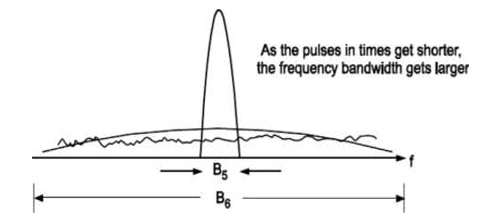
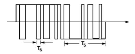
The pseudo noise (PN-code) is a binary signal which is produced at a much higher frequency than the data that is to be transmitted. Since this has a higher frequency, it has a large bandwidth, which spreads the signal in the frequency plane (i.e., it spreads its spectrum).
The nature of this signal makes it appear as random.
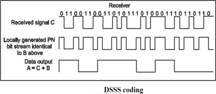
Signals generated with this technique appear as noise in the frequency domain. The wide bandwidth provided by the pseudo noise code allows the signal power to drop below the noise threshold without losing any information.
Special spreading codes like walsh code allow us to use DSSS in mobile communication and share bandwidth among several users.
Wireless Network
To set up an ad-hoc wireless network, each wireless adapter must be configured for mode instead of infrastructure mode, which is the mode used in networks where there is a central device like a router or server that manages network traffic. In addition, all wireless adapters on the network must use the same Service Set Identifier, or SSID, and the same wireless channel number.
Wireless networks cannot bridge to wired LANs or to the internet without installing a special-purpose network gateway.
Ad hoc networks make sense when needing to build a small, all-wireless LAN quickly for a minimum amount of money spent on equipment.
Ad-hoc networks also work well as a temporary fallback mechanism if equipment for an infrastructure mode network, such as a router or access point, fails.
Importance of Wireless Network Security
Networks are often secured given their usually temporary or impromptu nature. Without network access control, for example, networks can be open to attacks.
Devices in a network cannot disable SSID broadcasting in the way that devices in infrastructure mode can. Attackers generally will have little difficulty finding and connecting to a device if they get within signal range.
Authentication can help with this, but adhoc networks are inherently more vulnerable to security threats.
Security and Network Management Issues
Security and network management issues are as follows by using Cisco Clean Access software, the authority is able to suspend any client who misused the network Management staffs can manage the bandwidth & network traffic with help of software with help of Cisco Works LAN Management Solution (LMS), the authority can manage all ports on a switch easily.
Theory of Wireless Network Communication.
The growth of Wireless Local Area Network (WLANs) which was triggered by US Federal Communications Commission’s (FCC) decision to authorize the public use of the Industrial, Scientific and Medical (ISM) bands. This decision eliminated the need for companies and end users to obtain FCC licenses to operate their wireless products. Since then, there has been a substantial growth in area of WLANs.
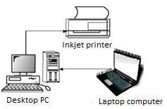
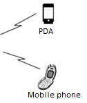
Fig- Wireless network example
Design of Wireless Network
In the design of a digital campus, both infrastructure and adhoc topologies will be used. Types of topologies chosen for the design will depend on the structure of the buildings. This will be discussed in each design. There are two types of WiFi, indoor and outdoor wireless AP (Access Point), which will be used. The outdoor AP, as well as the indoor AP will be connected as infrastructure WLAN. The purpose of installing an outdoor AP is to ensure the access to World Wide Web in any area in the campus. The wireless system will base on the IEEE 802.11 standard. This will ensure interoperability between the products from different manufacturers
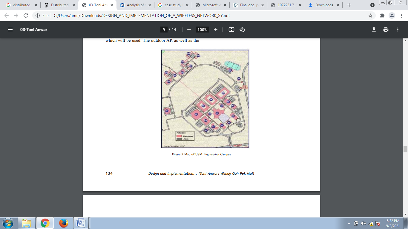
Fig- Showing wifi network in a campus.
Conclusion
The design in this research is based on the coverage characteristic of an Access Point. Access Point from different manufacturer may have different specifications. Hence analyses of the specifications and the building structure have to be done before the design of the wireless network. Some APs may have higher transmission power and higher gain antenna which are able to provide stronger signals. In this research, there are mathematical equations shown in order to predict the coverage of an AP. However, this prediction may differ from the measurement we obtained from the real environments. Therefore, mathematical model is used for design references. In order to get the exact coverage of an AP, coverage testing needs to be carried out. The testing can be done by using mobile devices.
References:
1. Kurose, Ross, “Computer Networking a Top-Down Approach Featuring the Internet”, Pearson, ISBN-10: 0132856204
2. L. Peterson and B. Davie, “Computer Networks: A Systems Approach”, 5th Edition, Morgan-Kaufmann, 2012.
3. Douglas E. Comer & M.S Narayanan, “Computer Network & Internet”, Pearson Education
4. William Stallings, “Cryptography and Network Security: Principles and Practice”, 4th Edition
5. Pachghare V. K., “Cryptography and Information Security”, 3rd Edition, PHI