Unit - 3
Network Layer
It is 3rd layer from bottom in OSI model and it serves as an
Intermediately between DLL and Transport layer.
Its unit of data transmission is packet
Network Layer Services
The third layer of OSI model is the Network Layer. It handles these service request from transport layer and forwards the service request to data link layer. It translates the logical addresses into physical addresses It determines the route from the source to destination and manage the traffic problems such as switching, routing and controls the congestion of data packets. The main role of the network layer is to move the packets from sending host to the receiving host.
The Functions of Network layer includes
a) Guaranteed delivery
b) Guaranteed delivery with bounded delay
c) In-order packet delivery
d) Guaranteed minimal bandwidth
e) Guaranteed maximum jitter
f) Security services
g) Guaranteed Delivery
This service guarantees that the packet arrives at the destination.
Guaranteed Delivery with Bounded Delay:
This service not only guarantees delivery of the packet but delivers within the specified host-to-host delay bound.
In-order Packet Delivery:
This service guarantees that packets arrive at the destination in the order that they were sent.
Guaranteed Minimal Bandwidth: This network layer service emulates the behavior of a transmission link of a specified bit rate between sending and receiving hosts.
As long as the sending host transmits bits at a rate below the specified bit rate, then no packet is lost and each packet arrives within a pre specified host-to-host delay.
Guaranteed Maximum Jitter:
This service guarantees that the amount of time between the transmission of two successive packets at the sender is equal to the amount of time between their receipt at the destination.
Security Services:
Using a secret session key known by source and destination host, the network layer in the source host could encrypt the payloads of all datagrams being sent to the destination host.
The network layer in the destination host would then be responsible for decrypting the payloads. With such a service, confidentiality would be provided to all transport layer segments between the source and destination hosts.
The network layer also provides data integrity and source authentication
services.
Packet Switching
Packet switching is a network switching technique which is connectionless. The message is divided and grouped into number of units called packets that are individually routed from source to destination. There is no need to establish a dedicated circuit for communication.
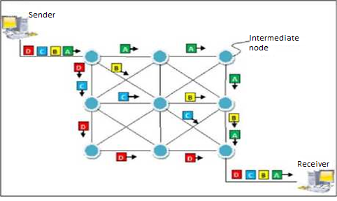
Fig. Packet Switching
Process
Each packet in a packet switching technique has two parts:
4- Header
4- Payload.
The header contains the addressing information of the packet which is used by the intermediate routers to direct it towards its destination.
The payload carries the actual data. A packet is transmitted when available in a node, based upon its header information. The packets of a message are not routed through the same path. So the packets in the message arrives in the destination out of order. It is the responsibility of the destination to reorder the packets to retrieve the original
message. The process is diagrammatically represented in the following figure. Here the message comprises of four packets, A, B, C and D, which may follow different routes from the sender to the receiver.
Advantages
1. Delay in delivery of packets is less because packets are sent when
available.
2. Switching devices does not require massive storage because they don’t
have to store the entire messages before forwarding them to the next node.
3. Data delivery can continue even if some parts of the network faces link
failure. Packets can be routed through other paths.
4. It allows simultaneous usage of same channel by multiple users.
Disadvantages
o They are unsuitable for applications that cannot afford delays in
communication like high quality voice calls.
o Packet switching high installation costs.
o They require complex protocols for delivery.
o Network problems may introduce errors in packets, delay in delivery of
packets or loss of packets.
Circuit Switching
This scheme provides a dedicated (virtual) circuit per call or session. The resources on the links (e.g. link bandwidth, switch capacity) all the way on the path between the communicating entities are reserved (in both directions) for a session and these resources are not shared with any other sessions.
That means, via circuit switching, there is an upper limit to the number of sessions that can be supported over a network. This gives circuit switched sessions a guarantee on the session quality (circuit-like performance), just like the session quality guaranteed by a phone connection, to some degree at least (e.g. When you are close enough to the nearest cell tower).
In order to be able to give such guarantees, your phone operator will not admit the call if the needed resources are not free. This is the same reason why it is difficult to make cellular phone calls at a concert or stadium where there are a lot of active calls using the same cell tower
IP addressing is classified into two types classless and class full addressing in class full addressing it is categorized into five classes from A to E on the basis of range of ip address.
IPv4 addresses 32-bit binary addresses which is divided into 4 octets used by the Internet Protocol OSI Layer 3 for delivering packet to a device located in same orremote network.MAC address known as Hardware address is a globally unique address whichrepresents the network card that cannot be changed.IPv4 address refers to a logical address, a configurable address which is used toidentify which network this host belongs to and the network specific host number.
An IPv4 address consists of two parts;
Network part
Host part
An example of IPv4 address is 192.168.10.100, which is actually 11000000.10101000.00001010.01100100.
For Each network, consists of two addresses one address is used to represent the network and one address is used for broadcast. Network address is an IPv4 address where all host bits are "0". Broadcast address is an IPv4 address where all host bits are "1".
In a network, the first IPv4 address is the network address and the last IPv4 address is the broadcast address.
All the usable IPv4 addresses in any IP network are between network address and broadcast address.
There are five IPv4 address Classes and certain special addresses.
Class A IPv4 addresses
Class A IPv4 addresses are specifically used for large networks. The left-most bit of the left most octet of Class A network is reserved as "0". The first octet of Class A IPv4 address identifies the Network and remaining three octets identify the host in that particular network (Network.Host. Host.Host). The 32 bits of a Class A IPv4 address can be represented as
Oxxxxxxx . Xxxxxxxx. Xxxxxxxx. Xxxxxxxx.
The minimum possible value for leftmost octet in binaries is 00000000 (decimal equivalent is 0) and the maximum possible value for the leftmost octet is 01111111 (decimal equivalent is 127).
Therefore, In Class A IPv4 address, leftmost octet must have a value between 0-127 (0.X.X.Xto 127.X.X.X). The network 127.0.0.0 is known as loopback network. The IPv4 address 127.0.0.1is used by host computer to send message back to itself. It is commonly used for troubleshooting and network testing.
They need an IPv4 addresses that is unique to particular network . 10.0.0.0 network belongs to Class A is reserved for private use and can be used inside any organization.
Class B IPv4 addresses
Class B IPv4 addresses are mainly used for medium-sized networks. Two left most bits of the left-most octet of a Class B network is reserved as "10". The first two octets of a Class B IPv4 address is used to identify Network and the remaining two octets are used to identify host in that particular network (Network-Network. Host.Host).
The 32 bits of a "Class B" IPv4 address can be represented as 1 Oxxxxxx . Xxxxxxxx. Xxxxxxxx. Xxxxxxxx.
The minimum possible value for the left-most octet in binaries is 10000000 (decimal equivalent is 128) and the maximum possible value for the left most octet is 10111111 (decimal equivalent is 191). Therefore, for Class B IPv4 address, left-most octet must have a value between 128-191 (128.X.X.Xto 191.X.X.X).
Class C IPv4 addresses
Class C IPv4 addresses used for small to mid-size businesses. Three left-most bits of the left most octet of a Class C network is reserved as "110". The first three octets of a Class C IPv4 address is used to identify the Network and the remaining one octet is used to identify the host in that particular network (Network-Network. Network-Host).
The 32 bits of a Class C IPv4 address can be represented as 11 Oxxxxx. Xxxxxxxx. Xxxxxxxx. Xxxxxxxx.
The minimum possible value for the left-most octet in binaries is 11000000 (decimal equivalent is 192) and the maximum possible value for the left most octet is 11011111 (decimal equivalent is 223).
Therefore for a "Class C" IPv4 address, left-most octet must have a value between 192-223 (192.X.X.X to 223.X.X.X).Networks starting from 192.168.0.0 to 192.168.255.0 are reserved for private use.
Class D IPv4 addresses
Class D IPv4 addresses known as multicast IPv4 addresses. Multicasting refers to a technique used to send packets from one device to various devices, without any packet duplication.
In multicasting, one packet is sent from a source and is replicated as needed in the network to reach as many end-users as necessary.
Four left-most bits of the left most octet of a Class D network is reserved as "1110". The other 28 bits are used to identify the multicast group (group of computers the multicast message is intended for).
The minimum possible value for the left most octet in binaries is 11100000 (decimal equivalent is 224) and the maximum possible value for the left most octet is 11101111 (decimal equivalent is 239).
Therefore, for a Class D IPv4 address, left-most octet must have a value between 224-239 (224.X.X.X to 239.X.X.X).
Class E IPv4 addresses
Class E is used for experimental purposes and cannot assign these IPv4 addresses to your devices. Four left most bits of the left-most octet of a "Class E" network is reserved as "1111". The minimum possible value for the left-most octet in binaries is 11110000 (decimal equivalent is 240) and the maximum possible value for the left-most octet is 11111111 (decimal equivalent is 255). Therefore, for a "Class E" IPv4 address, left most octet must have a value between 240-255 (240.X.X.X to 255.X.X.X).
IPV6 is next version of IPV4 it enhanced features in comparison With IPV4
Requirements for Next Generation IP
o Must provide more network addresses.
o Must provide for efficient route aggregation.
o Must adapt to mobile devices connecting with a multiplicity of datalink
methods with a minimum of network overhead.
o Must adapt to emerging home-entertainment-network market
o Must interoperate smoothly with IP4 during transition period, which could
last for many years.
IPv6 features
128-bit address, giving a total address space of 2128 possible addresses.
Scope field to simplify multicast addressing
Anycast address — like a multicast group, except that the packet must be
delivered to any one address in the group.
Header extensions allow new header types to be defined. Headers are
daisy-chained to arbitrary length. Implementations which do not recognize
a particular header type ignore it, and the protocol must work correctly in
this case.
Authentication and confidentiality feature similar to IPsec.
Packets can be labelled as belonging to a particular flow, so that QoS
parameters can be established for that flow optional
Base | Extension | ... | Extension | DATA... |
Fig-The general form of IPv6 datagram with multiple headers.
Base header required extension headers are optional
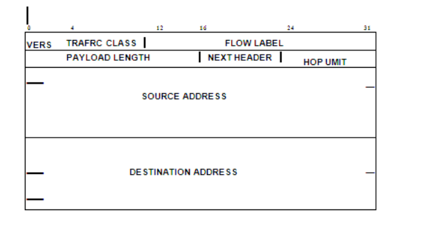
Fig- IPv6 Header
IPv6 header format. IPv6 headers are only twice as long as IPv4 headers, because
fragmentation and reassembly fields have been made optional
.
Base Header | TCP Segment |
Base Header | Route Header | TCP Segment |
Base Header | Route Header | Auth Header | TCP Segment |
NEXT=ROUTE | NEXT=AUTh | NEXT=TCP |
Network Address Translation (NAT)
NAT is a router function where IP addresses (and possibly port numbers) of IP datagrams are replaced at the boundary of a private network
• NAT is a method that enables hosts on private networks to communicate with hosts on the Internet
• NAT is run on routers that connect private networks to the public Internet, to replace the IP address-port pair of an IP packet with another IP address-port pair.
NOTE-NAT device has address translation table
Basic operation of NAT
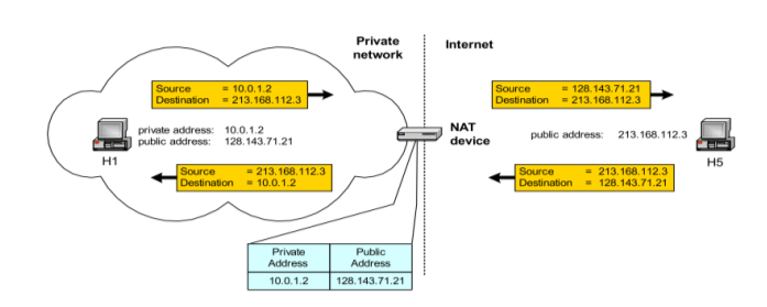
Fig-Pooling of IP addresses
• Scenario: Corporate network has many hosts but only a small number of public IP addresses
• NAT solution: Corporate network is managed with a private address space NAT device, located at the boundary between the corporate network and the public Internet, manages a pool of public IP addresses When a host from the corporate network sends an IP datagram to a host in the public Internet, the NAT device picks a public IP address from the address pool, and binds this address to the private address of the host
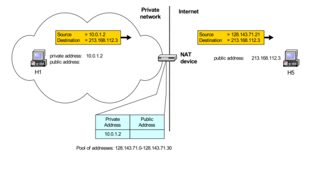
Fig-Supporting migration between network service providers
• Scenario: In CIDR, the IP addresses in a corporate network are obtained from the service provider. Changing the service provider requires changing all IP addresses in the network.
• NAT solution: Assign private addresses to the hosts of the corporate network NAT device has static address translation entries which bind the private address of a host to the public address. Migration to a new network service provider merely requires an update of the NAT device. The migration is not noticeable to the hosts on the network.
Note: The difference to the use of NAT with IP address pooling is that the mapping of public and private IP addresses is static.
Subnetting and CIDR
A sub network or subnet in an internetwork is a set of network interfaces that can physically reach each other over a single link (no routers in between). In order to identify subnets in a network, a simple recipe is to detach each router interface resulting in islands of isolated networks, each being a subnet
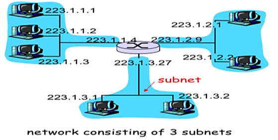

Fig -class full
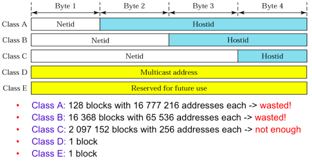
Fig- IPV4
Assigning class B would result in a waste of more than 63K IPv4 addresses andwe can make class B assignments to at most 16368 such organizations. On the other hand, assigning class C is not possible since class C gives only 256 distinct addresses in each block. A workaround for this problem would be to assign multiple class C blocks to the organization.
Due to deficiency of classful addressing, classless addressing and Classless Inter-Domain Routing (CIDR) were introduced. In classless addressing an IP address consists of a subnet part (higher order bits) and a host part (lower order bits). The subnet parts of all IP addresses in a given subnet are identical, i.e. all these IP addresses start with the same subnet prefix. We illustrate the notations used for subnet prefix and subnet mask in Fig.
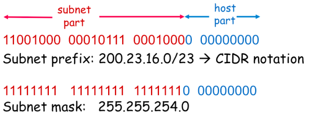
Fig- CIDR notation
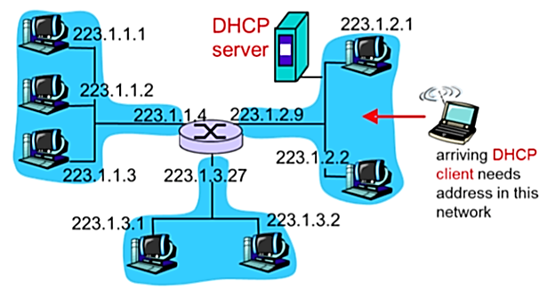
Subnetting maps an address to the host's location in a network topology .That is, hosts inside a subnet do not own their IP addresses by default. Newly joining hosts can lease' their IP addresses from a server for a certain time duration using the Dynamic Host Configuration Protocol (DHCP).
Address Resolution Protocol (ARP)
For communication, the host needs Layer-2 (MAC) address of destination machine which belongs to same broadcast domain or network.
The MAC address is physically burnt into Network Interface Card (NIC) of the machine which never changes.
While the IP address on public domain is rarely changed. If NIC changes MAC address also changes. Hence, for Layer-2 communication takes place and mapping between the two is required.
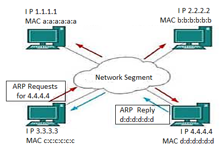
Fig. ARP
To know the MAC address of remote host on broadcast domain the computer that wishes to initiate communication sends out ARP broadcast message asking “Who has this IP address?
In broadcast all hosts on the network segment receive this packet and process it. ARP packet contains IP address of destination host, the sending host wishes to talk to. When host receives an ARP packet destined to it , it replies back with its own MAC address.
Once the host gets the destination MAC address it can communicate with remote host using Layer-2 link protocol.
This MAC to IP mapping is saved to ARP cache of sending and receiving hosts. If they want to communicate, they refer to their respective ARP cache. Reverse ARP is a mechanism where the host knows the MAC address of remote host but to communicate it requires IP address.
There are two types of ARP entries:
o Dynamic entry: It is an entry which is created automatically when the
sender broadcast its message to the entire network. Dynamic entries are not permanent, and they are removed periodically.
o Static entry: It is an entry where someone manually enters the IP to MAC address association by using the ARP command utility.
RARP (Reverse Address Resolution Protocol)
If the host wants to know its IP address, then it broadcast the RARP query
packet that contains its physical address to the entire network.
A RARP server on the network recognizes the RARP packet and responds
back with the host IP address.
The protocol used to obtain IP address from server is known as Reverse
Address Resolution Protocol. The message format of RARP protocol is similar to ARP protocol.
ICMP (Internet Control Message Protocol)
The ICMP is a network layer protocol used by hosts and routers to send notifications of IP datagram problems back to the sender.
ICMP uses echo test/reply to check whether the destination is reachable and responding.
ICMP handles both control and error messages, but the main function is to report the error but not to correct them.
An IP datagram contains the addresses of both source and destination, but it does not know the address of the previous router through which it has been passed. Due to this reason, ICMP can only send the messages to the source, but not to the immediate routers.
ICMP protocol communicates the error messages to the sender. ICMP messages cause the errors to be returned to the user processes.
ICMP messages are transmitted within IP datagram.
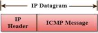
Fig- 20bytes ICMP
Error Reporting
ICMP protocol reports the error messages to the sender.
Five types of errors are handled by the ICMP protocol:
o Destination unreachable
o Source Quench
o Time Exceeded
o Parameter problems
o Redirection
o Destination unreachable: The message of "Destination Unreachable" is sent from receiver to the sender when destination cannot be reached, or packet is discarded when the destination is not reachable.
o Source Quench: The purpose of the source quench message is congestion control. The message sent from the congested router to the source host to reduce the transmission rate.
o ICMP will take the IP of the discarded packet and then add the source quench message to the IP datagram to inform the source host to reduce its transmission rate. The source host will reduce the transmission rate so that the router will be free from congestion.
o Time Exceeded: Time Exceeded is also known as "Time-To-Live". It is a parameter that defines how long a packet should live before it would be discarded.
IGMP
a) IGMP stands for Internet Group Message Protocol.
b) The IP protocol supports two types of communication.
c) Unicasting: It is a communication between one sender and one
receiver. Therefore, we can say that it is one-to-one communication.
d) Multicasting: Sometimes the sender wants to send the same
message to a large number of receivers simultaneously. This
process is known as multicasting which has one-to-many
communication.
e) The IGMP protocol is used by the hosts and router to support multicasting.
f) The IGMP protocol is used by the hosts and router to identify the hosts in a LAN that are the members of a group.
IGMP is a part of the IP layer, and IGMP has a fixed-size message.
The IGMP message is encapsulated within an IP datagram.

IGMP frame format
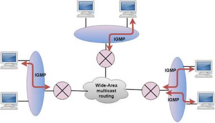
Fig- IGMP
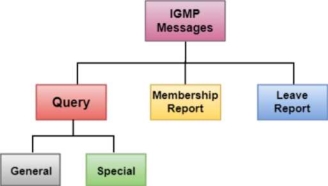
Note – IGMP message types
A routing protocol determines the packet routing behaviors of individual routers in a network. The routing protocol implementation at
Routers builds router forwarding tables, i.e. a mapping from destination host addresses to the outgoing link interfaces of the router. While forwarding concerns moving packets from an incoming link of the router input to the correct outgoing link, routing concerns determining the entire route taken by packets from source to destination
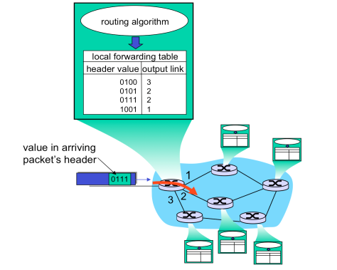
In static routing routing table is maintained manually by network administrator in this there is no need of having smart router or switch for network maintenance but in case of dynamic routing we need smart and intelligent switch/router for network maintenance here routing table is itself updated by following some dynamic routing algorithms like. RIP, DVP ,BGP etc.
Distance Vector Routing:
A distance-vector routing (DVR) protocol requires that a router inform its neighbours of topology changes periodically. Historically known as the old ARPANET routing algorithm (or known as Bellman-Ford algorithm).
Bellman Ford Basics - Each router maintains a Distance Vector table containing the distance between itself and ALL possible destination nodes. Distances , based on a chosen metric, are computed using information from the neighbours’ distance vectors.
Example - Consider 3-routers X5 Y and Z as shown in figure. Each router have their routing table. Every routing table will contain distance to the destination nodes.
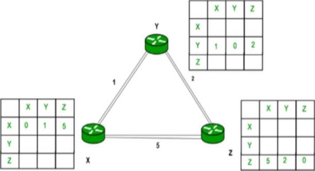
Consider router X 5 X will share it routing table to neighbors and neighbors will share it routing table to it to X and distance from node X to destination will be calculated using bellmen- ford equation.
Dx(y) = min { C(x5v) + Dv(y)} for each node y ∈ N
As we can see that distance will be less going from X to Z when Y is intermediate node (hop) so it will be update in routing table X.
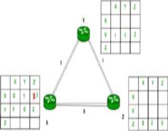
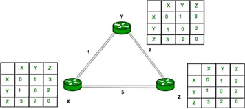
Finally, the routing table for all is shown above image.
Advantages Of Distance Vector routing
It is simpler to configure and maintain than link state routing.
Disadvantages Of Distance Vector routing -
It is slower to converge than link state.
It is at risk from the count-to-infinity problem.
It creates more traffic than link state since a hop count change must be propagated to all routers and processed on each router. Hop count updates take place on a periodic basis, even if there are no changes in the network topology, so bandwidth-wasting broadcasts still occur.
Link State Routing:
Link state routing is a technique in which each router shares the knowledge of its neighbourhood with every other router in the internetwork. The three keys to understand the Link State Routing algorithm:
o Knowledge about the neighbourhood: Instead of sending its routing table, a router sends the information about its neighbor hood only. A router broadcast its identities and cost of the directly attached links to ther routers.
o Flooding: Each router sends the information to every other router on the internetwork except its neighbours. This process is known as Flooding.
Every router that receives the packet sends the copies to all its neighbours. Finally, each and every router receives a copy of the same information.
o Information sharing: A router sends the information to every other router only when the change occurs in the information.
Link State Routing has two phases:
Reliable Flooding
o Initial state: Each node knows the cost of its neighbours.
o Final state: Each node knows the entire graph.
Route Calculation
Each node uses Dijkstra's algorithm on the graph to calculate the optimal routes to all nodes.
o The Link state routing algorithm is also known as Dijkstra's algorithm which is used to find the shortest path from one node to every other node in the network.
o The Dijkstra's algorithm is an iterative, and it has the property that after kth iteration of the algorithm, the least cost paths are well known for k destination nodes.
Path Vector Routing:
Path Vector Routing is routing algorithm in unicast routing protocol of network layer, and it is useful for interdomain routing.
The principle of path vector routing is similar to that of distance vector routing. It assumes that there is one node in each autonomous system that acts on behalf of the entire autonomous system is called Speaker node.
The speaker node in an AS creates a routing cable and advertises to the speaker node in the neighbouring ASs
A speaker node advertises the path, not the metrics of the nodes, in its autonomous system or other autonomous systems
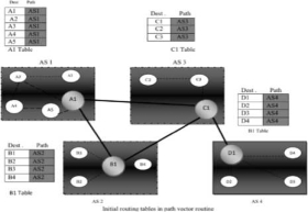
Fig-Vector Routine
It is the initial table for each speaker node in a system made four ASs. Here Node Al is the speaker node for ASI, Bl for AS2, Cl for AS3 and Dl for AS4, Node Al creates an initial table that shows Al to A5 and these are located in ASl, it can be reached through it
A speaker in an autonomous system shares its table with immediate neighbours, here Node Al share its table with nodes Bl and Cl , Node Cl share its table with nodes Al,Bl and Dl , Node Bl share its table with nodes Al and Cl , Node Dl share its table with node C1.
If router Al receives a packet for nodes A3 , it knows that the path is in ASl ,but if it receives a packet for Dl ,it knows that the packet should go from ASl ,to AS2 and then to AS3 ,then the routing table shows that path completely on the other hand if the node Dl in AS4 receives a packet for node A2,it knows it should go through AS4,AS3,and ASl
FUNCTIONS
PREVENTION OF LOOP
The creation of loop can be avoided in path vector routing .A router receives a message it checks to see if its autonomous system is in the path list to the destination if it is looping is involved and the message is ignored
POLICY ROUTING
When a router receives a messages it can check the path, if one of the autonomous system listed in the path against its policy, it can ignore its path and destination it does not update its routing table with this path or it does not send the messages to its neighbours.
OPTIMUM PATH
A path to a destination that is the best for the organization that runs the autonomous system.
OSFP: Open Shortest Path First
Another interior routing protocol OSPF divides an autonomous system into areas n To handle routing efficiently and in a timely manner.
OSPF works
A collection of networks, hosts, and routers all contained within an autonomous system Thus, an autonomous system can be divided into many different areas All networks inside an area must be connected
Routers inside an area flood the area with routing information Each area has a special router called area border routers n Summarize the information about the area and sent it to other areas.
Among the area inside an autonomous system is a special area called backbone n All of the areas inside an AS must be connected to the backbone The routers inside the backbone are called the backbone routers n A backbone router can also be an area border router
If the connectivity between a backbone and an area is broken n A virtual link must be created by the administration Each area has an area identification n The area identification of the backbone is zero.
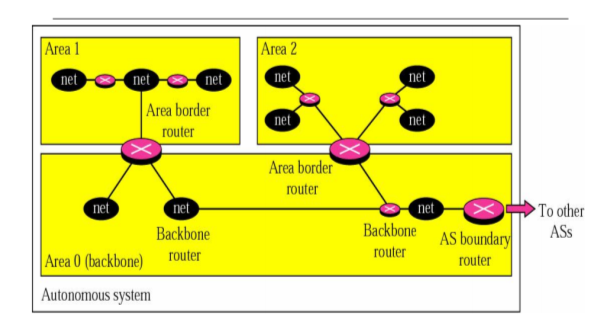
Fig- OSPF
Metrics
OSPF allows the administrator to assign a cost, called the metric, to each route o Metric can be based on a type of service n Minimum delay n Maximum throughput A router can have multiple routing tables n Each based on a different type of service.
BGP is classified as a path vector routing protocol.
Path Vector Routing.
Path Vector Routing is routing algorithm in unicast routing protocol of network layer, and it is useful for inter domain routing.
The principle of path vector routing is similar to that of distance vector routing. It assumes that there is one node in each autonomous system that acts on behalf of the entire autonomous system is called Speaker node.
The speaker node in an AS creates a routing cable and advertises to the speaker node in the neighbouring ASs
A speaker node advertises the path, not the metrics of the nodes, in its autonomous system or other autonomous systems.
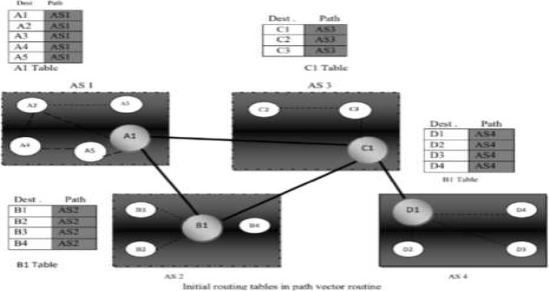
It is the initial table for each speaker node in a system made four ASs. Here Node Al is the speaker node for ASI, Bl for AS2, Cl for AS3 and Dl for AS4, Node Al creates an initial table that shows Al to A5 and these are located in ASl, it can be reached through it A speaker in an autonomous system shares its table with immediate neighbours ,here Node Al share its table with nodes Bl and Cl , Node Cl share its table with nodes Al,Bl and Dl , Node Bl share its table with nodes Al and Cl , Node Dl share its table with node C1 If router Al receives a packet for nodes A3 , it knows that the path is in ASl ,but if it receives a packet for Dl ,it knows that the packet should go from ASl ,to AS2 and then to AS3 ,then the routing table shows that path completely on the other hand if the node Dl in AS4 receives a packet for node A2,it knows it should go through AS4,AS3,and ASl.
FUNCTIONS PREVENTION OF LOOP The creation of loop can be avoided in path vector routing .A router receives a message it checks to see if its autonomous system is in the path list to the destination if it is looping is involved and the message is ignored POLICY ROUTING When a router receives a messages it can check the path, if one of the autonomous system listed in the path against its policy, it can ignore its
path and destination it does not update its routing table with this path or it does not send the messages to its neighbours. OPTIMUM PATH A path to a destination that is the best for the organization that runs the autonomous system.
MPLS
Multiprotocol label switching (MPLS) improves the overall performance and delay characteristics of the Internet. MPLS transmission is a special case of tunneling and is an efficient routing mechanism. Its connection-oriented forwarding mechanism, together with layer 2 label-based lookups, enables traffic engineering to implement peer-to-peer VPNs effectively.
MPLS adds some traditional layer 2 capabilities and services, such as traffic engineering, to the IP layer. The separation of the MPLS control and forwarding components has led to multilayer, multiprotocol interoperability between layer 2 and layer 3 protocols.
MPLS uses a small label or stack of labels appended to packets and typically makes efficient routing decisions. Another benefit is flexibility in merging IP-based networks with fast-switching capabilities.
This technology adds new capabilities to IP-based networks: • Connection-oriented QoS support • Traffic engineering • VPN support • Multiprotocol support Traditional IP routing has several limitations, ranging from scalability issues to poor support for traffic engineering.
The IP backbone also presents a poor integration with layer 2 existing in large service provider networks. For example, a VPN must use a service provider's IP network and build a private network and run its own traffic shielded from prying eyes. In this case, VPN membership may not be well engineered in ordinary IP networks and can therefore result in an inefficient establishment of tunnels.
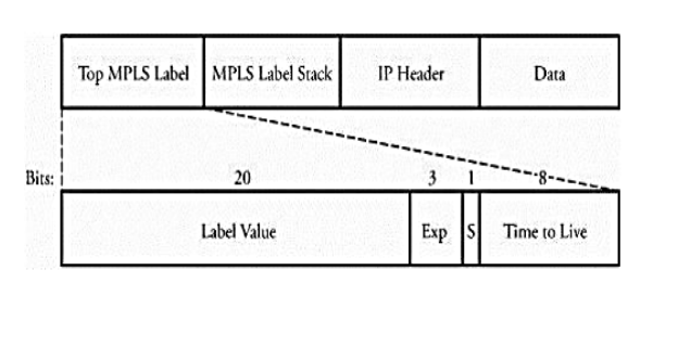
MPSL Packet Format MPLS uses label stacking to become capable of multilevel hierarchical routing. A label enables the network to perform faster by using smaller forwarding tables, a property that ensures a convenient scalability of the network.
Figure shows the MPLS header encapsulation for an IP packet. An MPLS label is a 32-bit field consisting of several fields as follows.
• Label value is a 20-bit field label and is significant only locally.
• Exp is a 3-bit field reserved for future experimental use.
• S is set to 1 for the oldest entry in the stack and to 0 for all other entries.
• Time to live is an 8-bit field used to encode a hop-count value to prevent packets from looping forever in the network.
Mobile Ad Hoc Networks (MANET)
Host movement frequent
Topology change frequent
No cellular infrastructure Multi hop wireless links.
Data must be routed via intermediate nodes.

Need of MANET
Setting up of fixed access points and backbone infrastructure is not always viable Infrastructure may not be present in a disaster area or war zone Infrastructure may not be practical for short range radios; Bluetooth (range ~ 10m) Ad hoc networks. Do not need backbone infrastructure support are easy to deploy Useful when infrastructure is absent, destroyed or impractical
Application
Personal area networking cell phone, laptop, ear phone, wrist watch Military environments soldiers, tanks, planes Civilian environments taxi cab network meeting rooms sports stadiums boats, small aircraft Emergency operations search and rescue policing and fire fighting
Ad-Hoc On Demand Vector Routing protocol (AODV)
It is a reactive or on-demand routing protocol. It is an extension of dynamic source routing protocol (DSR) and it helps to remove the disadvantage of dynamic source routing protocol.
In DSR, after route discovery, when the source mobile node sends the data packet to the destination mobile node, it also contains the complete path in its header.
In this as the network size increases, the length of the complete path also increases and the data packet’s header size also increases which makes the whole network slow.
Hence, AODV Routing protocol came as solution to it. The main difference lies in the way of storing the path, AODV stores the path in the routing table whereas DSR stores it in the data packet’s header itself. It also operates in two phases in the similar fashion: Route discovery and Route maintenance.
Dynamic Source Routing protocol (DSR):
It also is a reactive or on-demand routing protocol. In this type of routing, the route is discovered only when it is required or needed. The process of route discovery occurs by flooding the route request packets throughout the mobile network.
Phases:
Route Discovery:
This phase determines the most optimal path for the transmission of data packets between the source and the destination mobile nodes.
Route Maintenance:
This phase performs the maintenance work of the route as the topology in the mobile ad-hoc network is dynamic in nature and hence, there are many cases of link breakage resulting in the network failure between the mobile nodes.
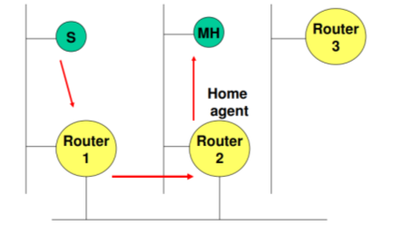
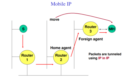
Mobile IP
Mobile IP Routing is based on IP destination address, network prefix determines physical subnet change of physical subnet implies change of IP address to have a topological correct address (standard IP) or needs special entries in the routing tables
• Changing the IP-address is used for adjusting the host IP address depending on the current location almost impossible to find a mobile system, DNS updates are too slow TCP connections break security problems .
• Change/Add routing table entries for mobile hosts does not scale with the number of mobile hosts and frequent changes in their location
Requirements to Mobile IP
• Compatibility support of the same layer 2 protocols as IP no changes to current end-systems and routers required mobile end-systems can communicate with fixed systems
• Transparency mobile end-systems keep their IP address continuation of communication after interruption of link possible point of connection to the fixed network can be changed
• Efficiency and scalability only little additional messages to the mobile system required (connection typically via a low bandwidth radio link) world-wide support of a large number of mobile systems
• Security authentication of all registration messages
Terminology
• Mobile Node (MN) – system (node) that can change the point of connection to the network without changing its IP address
• Home Agent (HA) – system in the home network of the MN, typically a router registers the location of the MN, tunnels IP datagrams to the COA
• Foreign Agent (FA) – system in the current foreign network of the MN, typically a router typically the default router for the MN
• Care-of Address (COA) – address of the current tunnel end-point for the MN (at FA or MN) actual location of the MN from an IP point of view can be chosen, e.g., via DHCP • Correspondent Node (CN)
Network Layer Services
- The third layer of OSI model is the Network Layer. It handles the
service - Request from transport layer and forwards the service request to
data link - Layer.
- It translates the logical addresses into physical addresses.
- It determines the route from the source to destination and manages
the traffic problems such as switching, routing and controls the
congestion of data packets. - The main role of the network layer is to move the packets from
sending host to the receiving host.
Unicast Routing
Unicast means the transmission from single sender to a single receiver.
It is a point to point communication between sender and receiver.
There are various unicast protocols such as TCP, HTTP, etc.
TCP is the mostly used unicast protocol. It is a connection- oriented protocol that relay on acknowledgement from the receiver side.
HTTP stands for Hyper Text Transfer Protocol. It is an object -oriented protocol for communication.
Use of routing protocol
A routing protocol determines the packet routing behaviors
Of individual routers in a network. The routing protocol implementation at routers builds router forwarding tables, i.e. a mapping from destination host addresses to the outgoing link interfaces of the router. While forwarding concerns moving packets from an incoming link of the router input to the correct outgoing link, routing concerns determining the entire route taken by packets from source to destination.
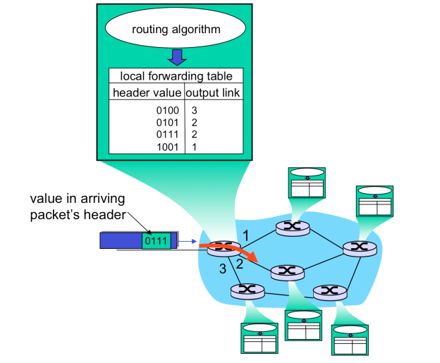
Fig- Showing routing
Above figure shows how a forwarding table of a router could look in principle, with one entry per destination IP. However, such a forwarding table is impossible to maintain and use for a simple reason. Even with IPv4 addresses consisting of 32 bits there would need to be around 4 billion entries in such a forwarding table and every forwarding operation would require a look-up among these entries. Furthermore, the amount of information exchange of the routing protocol for maintaining forwarding tables of routers would cause a constant state of
Congestion, rendering the Internet unusable for any other data communication.
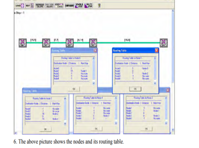
Introduction To simulate the distance vector routing protocol to maintain routing tables.
As the traffic and topology of the network changes.
Hardware Requirement
• 3PCs with NIU card
• Network Emulation Unit
• Jumper Cables
Background
The name distance vector is derived from the fact that routes are advertised as vectors of (distance, direction), where distance is defined in terms of a metric and direction is defined in terms of the next-hop router. For example, "Destination A is a distance of 5 hops away, in
The direction of next-hop router X." As that statement implies, each router learns routes from its neighboring routers' perspectives and then advertises the routes from its own perspective. Because each router depends on its neighbors for information, which the neighbors in turn
May have learned from their neighbors, and so on, distance vector routing is sometimes facetiously referred to as "routing by rumor."
The common Characteristics are Periodic Updates Periodic updates means that at the end of a certain time period, updates will be transmitted. Neighbors .In the context of routers, neighbors always mean routers sharing a common data link.
Broadcast Updates When a router first becomes active on a network, how does it find other routers and how does it announce its own presence? Several methods are available.
Full Routing Table Updates
Most distance vector routing protocols take the very simple approach of telling their neighbors everything they know by broadcasting their entire route table, with some exceptions that are covered in following sections.
Split Horizon
A route pointing back to the router from which packets were received is called a reverse route. Split horizon is a technique for preventing reverse routes between two routers.
References:
1. Kurose, Ross, “Computer Networking a Top Down Approach Featuring the Internet”, Pearson, ISBN-10: 0132856204
2. L. Peterson and B. Davie, “Computer Networks: A Systems Approach”, 5th Edition, Morgan-Kaufmann, 2012.
3. Douglas E. Comer & M.S Narayanan, “Computer Network & Internet”, Pearson Education
4. William Stallings, “Cryptography and Network Security: Principles and Practice”, 4th Edition
5. Pachghare V. K., “Cryptography and Information Security”, 3rd Edition, PHI