Unit - 4
Transport Layer
Introduction
The transport layer is known for process to process delivery in computer network it is prime task.
The Network layer protocols are largely concerned with finding a path through the network from a source host to a destination host. The Network layer doesn't provide an interface for application processes. Above the Network layer is the
Transport layer
The Transport layer provides an application process interface for actually connecting one process to another via the underlying network. The goal of the Transport layer is application processes should communicate without needing to consider the network technology. The Transport layer is an important layer in the protocol stack and perhaps the only layer seen by the ordinary users of the network. It is like an outer skin of the network which hides all the organs and functions of the network.
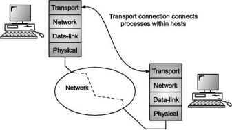
Fig. Transport layer
Its main task is to provide reliable connection from a network application running on a source computer to its corresponding application running on the destination computer. The connection could be both connectionless and connection-oriented. The OSI model specifies the Transport layer as providing only connection-oriented services. In TCP/IP standards, the Transport layer has provision for both connectionless and connection-oriented services.
Services of transport layer
The ultimate goal of the transport layer is to provide efficient, reliable, and cost- effective service to its users.
To achieve this goal, the transport layer takes help of the services provided by the network layer. The hardware and/or software within the transport layer that does the work is called the transport entity.
The transport entity can be located in the operating system kernel, in a separate user process, in a library package bound into network applications, or conceivably on the network interface card.
Similar to the network services, transport layer also contains two types of transport service.
Connectionless: It is very much similar to the connectionless network service.
Connection Oriented: The connection-oriented transport service is similar to the connection-oriented network service in many ways.
In both cases, connections have three phases:
a) Establishment,
b) Data transfer and
c) Release.
Addressing and flow control are also similar in both layers.
If the transport layer service is so similar to the network layer service, why are there two distinct layers?
The transport code runs completely on the users' machines, but the network layer mostly runs on the routers.
The users have no real control over the network layer, so they cannot solve the problem of poor service by using better routers or putting more error handling in the data link layer.
The only possibility is to put on top of the network layer another layer that improves the quality of the service. If, in a connection-oriented subnet, a transport entity is informed halfway through a long transmission so that its network connection has been abruptly terminated, with no indication of what has happened to the data currently in transit, it can set up a new network connection to the remote transport entity. Using this new network connection, it can send a query to its peer asking which data arrived and which did not, and then pick up from where it left off. In essence, the existence of the transport layer makes it possible for the transport service to be more reliable than the underlying network service.
Lost packets and garbled data can be detected and compensated for by the transport layer.
Advantage of Transport Layer
By using the transport layer, application programmers can write code according to a standard set of primitives and have these programs work on a wide variety of networks, without having to worry about dealing with different subnet interfaces and unreliable transmission.
Socket
Sockets are commonly used for client/server communication. Typical system configuration places the server on one machine, with the clients on other machines. The clients connect to the server, exchange information, and then disconnect. The client and server processes only communicate with each other if and only if there is a socket at each end.
There are three types of sockets
1) The stream socket
2) The packet/datagram socket
3) The row socket
All these sockets can be used in TCP/IP environment. These are explained below:
The Stream Socket: Features of stream socket are as follows: Connection-oriented Two-way communication
Reliable (error free), in order delivery
Can use the Transmission Control Protocol (TCP) e.g., telnet, ssh, http The Datagram Socket: Features of datagram socket are as follows:
Connectionless, does not maintain an open connection,
Each packet is independent can use the User Datagram Protocol (UDP) e.g., IP telephony Row Socket:
• Use protocols like ICMP or OSPF because these protocols do not use either stream packets or datagram packets.
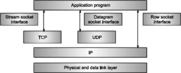
Fig: Types of sockets

Socket Address:
Process to process delivery needs two addresses.
IP address and Port number at each end to make a connection Socket address is the combination of IP address and the port number.
Socket Characteristics:
A socket is represented by an integer value. That integer is called a "socket descriptor". A socket exists as long as the process maintains an open link to the socket. You can name a socket and use it to communicate with other sockets in a communication domain. Sockets perform the communication when the server accepts connections from them, or when it exchanges messages with them.
Steps in socket programming
Figure below specifies an outline of client server network interaction diagram.
By observing Figure below, we can state the steps followed for socket programming.

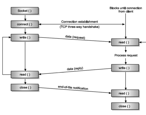
Firstly, server creates a socket. On successful creation of socket, socket primitive returns a file descriptor (also called as socket descriptor) that has been used in the future to refer the server socket.
Assigns local address and port number to the newly created socket using BIND. We need to associate an IP address and port number to our application.
A client that wants to connect to our server needs both of these details in order to connect to our server. Notice the difference between bind function and the connect function of the client. The connect function specifies a remote address that the client wants to connect to, while here, the server is specifying to the bind function a local IP address of one of its Network Interfaces and a local port number.
LISTEN call allocates some space. Queue is implemented by using this space. When number of clients tries to connect the server, they send the connection requests.
These connection requests are then stored in the queue and after that these requests are processed by the server one by one by using FIFO method. ACCEPT is used for blocking the waiting incoming connections.
Client Side:
Creates a socket using SOCKET primitive Uses CONNECT primitive for initiating the connection process with the server.
When server accepts the connection, the connection gets established. After that data is send and receive from the server. Connection release with sockets is symmetric. When both sides have executed a CLOSE primitive, the connection is released.
Communication Using TCP
Now let’s discuss connection-oriented, concurrent communication using the service of TCP.
Server Process
The server process starts first. It calls the socket function to create a socket, which we call the listen socket. This socket is only used during connection establishment. The server process then calls the bind function to bind this connection to the socket address of the server computer.
The server program then calls the accept function. This function is a blocking function; when it is called, it is blocked until the TCP receives a connection request (SYN segment) from a client. The accept function then is unblocked and creates a new socket called the connect socket that includes the socket address of the client that sent the SYN segment.
After the accept function is unblocked, the server knows that a client needs its service. To provide concurrency, the server process (parent process) calls the fork function. This function creates a new process (child process), which is exactly the same as the parent process. After calling the fork function, the two processes are running concurrently, but each can do different things. Each process now has two sockets: listen and connect sockets. The parent process entrusts the duty of serving the client to the hand of the child process and calls the accept function again to wait for another client to request connection. The child process is now ready to serve the client.
It first closes the listen socket and calls the recv function to receive data from the client.
The recv function, like the recv from function, is a blocking function; it is blocked until a segment arrives.
The child process uses a loop and calls the recv function repeatedly until it receives all segments sent by the client. The child process then gives the whole data to a function (we call it Iiandle Request), to handle the request and return the result. The result is then sent to the client in one single call to the send function.
The server may use many other functions to receive and send data, choosing the one which is appropriate for a particular application.
Second, we assume that size of data to be sent to the client is so small that can be sent in one single call to the send function; otherwise, we need a loop to repeatedly call the send function.
Third, although the server may send data using one single call to the send function, TCP may use several segments to send the data. The client process, therefore, may not receive data in one single segment.
TCP Connection Establishment
For establishing a connection, the server, passively waits for an incoming connection by executing the LISTEN and ACCEPT primitives.
The other side, say, the client, executes a CONNECT primitive, specifying the IP address and port to which it wants to connect.
The CONNECT primitive sends a TCP segment with the SYN bit 1 and ACK bit O and waits for a response.
When this segment arrives at the destination, the TCP entity there checks to see if there is a process that has done a LISTEN on the port given in the Destination port field. If not, it sends a reply with the RST bit on to reject the connection. If some process is listening to the port, that process is given the incoming TCP segment. It can then either accept or reject the connection. After acceptance of the segment, an acknowledgement segment is sent back. The sequence of TCP segments sent in normal is shown in Fig.
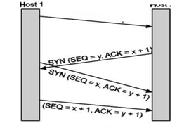
If two hosts simultaneously attempt to establish a connection between the same two sockets, the sequence of events is as illustrated in Fig.
The result of these events is that just one connection is established, not two because connections are identified by their end points.
TCP Connection Release
To release a connection, either party can send a TCP segment with the FIN bit set, which means that it has no more data to transmit. When the FIN is acknowledged, that direction is shut down for new data. Data may continue to flow indefinitely in the other direction, however. When both directions have been shut down, the connection is released. Four TCP segments are needed to release the connection: one FIN and one ACK for each direction.
TCP is stream-oriented protocol. It allows sending and receiving process to send and accept data as a stream of bytes.
TCP creates an environment, in which an imaginary “tube” connects the sending and receiving process. This tube carries their data across the internet.
This imaginary environment is shown in Fig. 5.13, where sender’s process writes a stream of bytes on the tube at one end and the receiver’s process reads the stream of bytes from the other end.
Sending Process Receiving Process
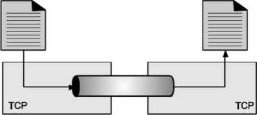
Fig. Stream delivery
Because the sending and receiving processes may not read or write the data at the same speed, TCP needs buffer storage.
Hence, TCP contains two buffers:
Sending buffer and Receiving buffer Used at sender and receiver side process respectively.
These buffers can be implemented by using a circular array of 1-byte locations as shown in Fig. For simplicity we have shown buffers of smaller size. Practically, the buffers are much larger than this.
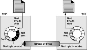
Fig. shows data movement in one direction. At the sending site, the buffer contains three types of compartments. The white section contains empty compartments, which can be filled by the sending process. The area holds bytes that have been sent but not yet acknowledged. TCP keeps these bytes in the buffer until it receives the acknowledgement. The black area contains bytes to be sent by the sending TCP process.
TCP may be able to send only part of this black section. This could be due to the slowness of the receiving process or due to the network congestion problem.
When the bytes in the gray section are acknowledged, the chambers become free and get available for use to the sending process. At receiver side, the circular buffer is divided into two areas (white and gray).
The white area contains empty compartments, to be filled by bytes, received from the network.
The gray area contains received bytes that can be read by the receiving process. Once the byte is read by the receiving process, the compartment is freed and added to the pool of empty compartments.
Buffering is used to handle the difference between the speed of data transmission and data reception. But only buffering is not enough, we need one more step before we can send the data. IP layer, as a service provider for TCP, needs to send data in packets, not as a stream of bytes. At transport layer, TCP groups the number of bytes together into a packet called as a segment; TCP adds a header to each segment and delivers the segment to the IP layer for transmission. The segments are encapsulated in an IP datagram and then transmitted.
MULTIPLEXING: In networks that use virtual circuits within the subnet, each open connection consumes some table space in the routers for the entire duration of the connection. If buffers are dedicated to the virtual circuit in each router as well, a user who left a terminal logged into a remote machine, there is need for multiplexing. There are 2 kinds of multiplexing
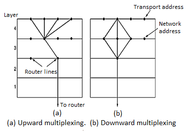
UP-WARD MULTIPLEXING: In the figure, all the 4 distinct transport connections use the same network connection to the remote host. When connect time forms the major component of the carrier’s bill, it is up to the transport layer to group port connections according to their destination and map each group onto the minimum number of port connections.
DOWN-WARD MULTIPLEXING: If too many transport connections are mapped onto the one network connection, the performance will be poor.
If too few transport connections are mapped onto one network connection, the service will be expensive. The possible solution is to have the transport layer open multiple connections and distribute the traffic among them on round-robin basis, as indicated in the below figure: With ‘k’ network connections open, the effective band width is increased by a factor of ‘k’.
TCP CONGESTION CONTROL:
TCP does to try to prevent the congestion from occurring in the first place in the following way: When a connection is established, a suitable window size is chosen and the receiver specifies a window based on its buffer size. If the sender sticks to this window size, problems will not occur due to buffer overflow at the receiving end. But they may still occur due to internal congestion within the network. Let’s see this problem occurs.
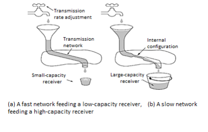
In fig (a): We see a thick pipe leading to a small capacity receiver. As long as the sender does not send more water than the bucket can contain, no water will be lost. In fig (b): The limiting factor is not the bucket capacity, but the internal carrying capacity of the n/w. If too much water comes in too fast, it will backup and some will be lost. When a connection is established, the sender initializes the congestion window to the size of the max segment in use our connection. It then sends one max segment. if this max segment is acknowledged before the timer goes off, it adds one segment s worth of bytes to the congestion window to make it two maximum size segments and sends 2 segments.
As each of these segments is acknowledged, the congestion window is increased by one max segment size. When the congestion window is ‘n’ segments, if all ‘n’ are acknowledged on time, the congestion window is increased by the byte count corresponding to ‘n’ segments.
The congestion window keeps growing exponentially until either a time out occurs or the receiver’s window is reached. The internet congestion control algorithm uses a third parameter, the “threshold” in addition to receiver and congestion windows.
Different congestion control algorithms used by TCP are: RTT variance Estimation.
Exponential RTO back-off Re-transmission Timer Management
Karn’s Algorithm
Slow Start
Dynamic window sizing on congestion
Fast Retransmit Window Management
Fast Recovery
TCP (Transmission Control Protocol)
TCP is a connection oriented, reliable transport protocol. It lies between application layer and network layer and serves as intermediary between application programs and network operation. TCP provides a way for applications to send encapsulated IP packets by establishing a connection. It uses flow and error control mechanisms in the transport layer. It helps in process-to-process communication; it uses port numbers to accomplish this task. It is a full duplex protocol, meaning that each TCP connection supports a pair of byte streams, one flowing in each direction.
TCP also implements a congestion-control mechanism.
Introduction to TCP
TCP (Transmission Control Protocol) was specifically designed to provide a reliable end-to-end delivery of data over an unreliable internetwork. An internetwork differs from a single network because different parts may have wildly different topologies, protocols, bandwidths, delays, packet sizes, and other parameters.
TCP was designed to dynamically adapt to properties of the internetwork and to be robust to face many kinds of failures.
The reliability mechanism of TCP allows devices to deal with lost, delayed, or duplicate packets.
The IP layer gives no guarantee that datagram’s will be delivered properly, so by using the timeout mechanism; the lost packets are detected and then retransmitted.
Datagrams may arrive in the wrong order; so it is up to TCP to reassemble them into messages in the proper sequence. Following are some of the services offered by TCP to the processes at the application layer
a) Stream delivery service.
b) Full Duplex service.
c) Connection oriented service.
d) Reliable service.
TCP Services
Stream Delivery Service
TCP is stream-oriented protocol. It allows sending and receiving process to send and accept data as a stream of bytes.
TCP creates an environment, in which an imaginary “tube” connects the sending and receiving process. This tube carries their data across the internet.
This imaginary environment is shown in Fig. 5.13, where sender’s process writes a stream of bytes on the tube at one end and the receiver’s process reads the stream of bytes from the other end.
Sending Process Receiving Process
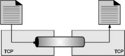
Fig. Stream delivery
Because the sending and receiving processes may not read or write the data at the same speed, TCP needs buffer storage. Hence, TCP contains two buffers.
Sending buffer and Receiving buffer Used at sender and receiver side process respectively. These buffers can be implemented by using a circular array of 1-byte locations as shown in Fig. For simplicity we have shown buffers of smaller size. Practically, the buffers are much larger than this.
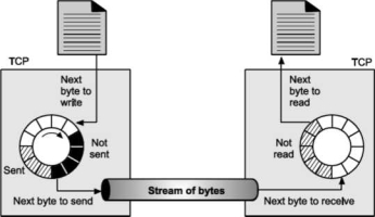
Fig – Sending and receiving process.
Fig. Shows data movement in one direction. At the sending site, the buffer contains three types of compartments. The white section contains empty compartments, which can be filled by the sending process. The area holds bytes that have been sent but not yet acknowledged. TCP keeps these bytes in the buffer until it receives the acknowledgement.
The black area contains bytes to be sent by the sending TCP process.
TCP may be able to send only part of this black section. This could be due to the slowness of the receiving process or due to the network congestion problem.
When the bytes in the gray section are acknowledged, the chambers become free and get available for use to the sending process. At receiver side, the circular buffer is divided into two areas (white and gray).
The white area contains empty compartments, to be filled by bytes, received from the network.
The gray area contains received bytes that can be read by the receiving process. Once the byte is read by the receiving process, the compartment is freed and added to the pool of empty compartments. Buffering is used to handle the difference between the speed of data transmission and data reception. But only buffering is not enough, we need one more step before we can send the data. IP layer, as a service provider for TCP, needs to send data in packets, not as a stream of bytes.
At transport layer, TCP groups the number of bytes together into a packet called as a segment; TCP adds a header to each segment and delivers the segment to the IP layer for transmission.
The segments are encapsulated in an IP datagram and then transmitted.
Full Duplex Communication Service:
TCP provides full duplex service, when data can flow in both directions at the same time. Each TCP then have a sending and receiving buffer and segments in both directions.
Connection Oriented Service:
TCP is a connection-oriented protocol.
When one process at site A wants to send and receive data from another process at site B, following things take place: The two TCPs establish a connection between them. Data are exchanged in both the directions. The connection is terminated.
Note: that the connection is virtual and not the physical.
Reliable Service.
TCP is reliable transport protocol. It uses acknowledgement mechanism to check the safe and sound arrival of the data.
User Datagram Protocol (UDP) It is a connectionless, unreliable transport protocol. UDP provides a way for applications to send encapsulated IP datagram’s without having to establish a connection.
UDP transmits segments consisting of an 8-byte header followed by the pay load. The data segment sent using the UDP protocol is called as datagram. It serves as intermediary between the application programs and network operations. It helps in process-to-process communication; it uses port numbers to accomplish this task. Another responsibility is to provide control mechanism at transport layer. It performs very limited error checking. It does not contain flow control and acknowledgement mechanism for the received packets. It is very simple protocol with a minimum overhead. If process wants to send a small message and does not care much about the reliability, it can use UDP.
1. User Datagram
UDP packets, called user data grams, have a fixed size header of 8 bytes. Following Fig. Shows the format of a user datagram header. Having size 32 bits.

Fig. User datagram header format
The fields are as follows
Source Port Number
This is the port number used by the process running on source host.
It is 16 bit long, which means that port number can range from 0 to 65,535. If the source host is the client (a client sending a request), the port number, in most cases is an ephemeral port number requested by the process and chosen by the UDP software running on the source host. If source host is server (a server sending a response), the port number, in most cases is a well-known port number.
Destination Port Number
This is a port number used by the process running on the destination host. It is also 16 bit long. If destination host is the server, the port number in most cases, is a well-known port. If destination host is a client, the port number in most cases is ephemeral port number. In this case, server copies the ephemeral port number it has received in the request packet.
UDP Length
This is a 2-byte (16 bit) field that defines the total length of user datagram (i.e., header + data). The 16 bit can define total length of 0 to 65,535 bytes. However, the total length needs to be much less because an UDP user datagram is stored in an IP datagram with the total length of 65535 bytes. The length field in a UDP user datagram is actually not necessary. A user datagram is encapsulated in an IP datagram. There is a field in the IP datagram that defines the total length. There is another field in the IP datagram that defines the length of the header. So, after subtracting the value of second field from the first, we can find out the length of UDP datagram that is encapsulated in an IP datagram.
UDP length = IP length - IP header’s length However, the designers of the UDP protocol felt that it was more efficient for the destination UDP to calculate the length of the data from the information provided in the UDP user datagram rather than asking the IP software to supply this information. Also, we should remember that when the IP software delivers the UDP user datagram to the UDP layer, it has already dropped the IP header.
UDP Checksum
This field is used to detect errors over the entire user datagram (header + data). UDP checksum calculation involves three sections: the pseudo header, the UDP header and data coming from the application layer. (Pseudo header is a part of the header of IP packet in which user datagram is to be encapsulated.)
Stream Control Transmission Protocol (SCTP)
The Stream Control Transmission Protocol (SCTP) provides a general-purpose transport protocol for message-oriented applications. It is a reliable transport protocol for transporting stream traffic, can operate on top of unreliable connectionless networks, and offers acknowledged and non-duplicated transmission data on connectionless networks (datagrams).
SCTP has the following features
• The protocol is error free. A retransmission scheme is applied to compensate for loss or corruption of the datagram, using checksums and sequence numbers.
• It has ordered and unordered delivery modes.
• SCTP has effective methods to avoid flooding congestion and masquerade attacks.
• This protocol is multipoint and allows several streams within a connection. In TCP, a stream is a sequence of bytes in SCTP, a sequence of variable sized messages. SCTP services are placed at the same layer as TCP or UDP services. Streaming data is first encapsulated into packets, and each packet carries several correlated chunks of streaming details.
SCTP Packet Structure

A chunk header starts with a chunk type field used to distinguish data chunks and any other types of control chunks. The type field is followed by a flag field and a chunk length field to indicate the chunk size. A chunk, and therefore a packet, may contain either control information or user data. The common header begins with the source port number followed by the destination port number. SCTP uses the same port concept as TCP or UDP does. A 32-bit verification tag field is exchanged between the end-point servers at startup to verify the two servers involved. Thus, two tag values are used in a connection. The common header consists of 12 bytes. SCTP packets are protected by a 32-bit checksum. The level of protection is more robust than the 16-bit checksum of TCP and UDP.
Real Time Transport Protocol (RTP)
In real time applications, a stream of data is sent at a constant rate. This data must be delivered to the appropriate application on the destination system, using real time protocols. The most widely applied protocol for real time transmission is the Real Time Transport Protocol (RTP), including its companion version Real Time Control Protocol (RTCP).
UDP cannot provide any timing information. RTP is built on top of the existing UDP stack. Problems with using TCP for real time applications can be identified easily.
Real time applications may use multicasting for data delivery. As an end-to-end protocol, TCP is not suited for multicast distribution. TCP uses a retransmission strategy for lost packets, which then arrive out of order. Real time applications cannot afford these delays.
TCP does not maintain timing information for packets. In real time applications, this would be a requirement.
The real-time transport protocol (RTP) provides some basic functionalities to real-time applications and includes some specific functions to each application. RTP runs on top of the transport protocol as UDP.UDP is used for port addressing in the transport layer and for providing such transport layer functionalities as reordering. RTP provides application-level framing by adding application layer headers to datagrams. The application breaks the data into smaller units, called application data units (ADUs). Lower layers in the protocol stack, such as the transport layer, preserve the structure of the ADU.
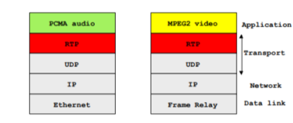
Congestion control
TCP does to try to prevent the congestion from occurring in the first place in the following way: When a connection is established, a suitable window size is chosen and the receiver specifies a window based on its buffer size. If the sender sticks to this window size, problems will not occur due to buffer overflow at the receiving end. But they may still occur due to internal congestion within the network. Let’s see this problem occurs.
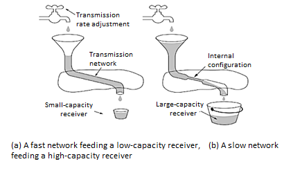
In fig (a): We see a thick pipe leading to a small capacity receiver. As long as the sender does not send more water than the bucket can contain, no water will be lost. In fig (b): The limiting factor is not the bucket capacity, but the internal carrying capacity of the n/w. If too much water comes in too fast, it will backup and some will be lost. When a connection is established, the sender initializes the congestion window to the size of the max segment in use our connection. It then sends one max segment. If this max segment is acknowledged before the timer goes off, it adds one segment s worth of bytes to the congestion window to make it two maximum size segments and sends 2 segments.
As each of these segments is acknowledged, the congestion window is increased by one max segment size. When the congestion window is ‘n’ segments, if all ‘n’ are acknowledged on time, the congestion window is increased by the byte count corresponding to ‘n’ segments.
The congestion window keeps growing exponentially until either a time out occurs or the receiver’s window is reached. The internet congestion control algorithm uses a third parameter, the “threshold” in addition to receiver and congestion windows.
QOS
QoS refers to the capability of a network to provide better service to selected network traffic over various technologies, including Frame Relay, Asynchronous Transfer Mode (ATM), Ethernet and 802.1 networks, SONET, and IP routed networks that may use any or all of these underlying technologies. Primary goals of QoS include dedicated bandwidth, controlled jitter and latency (required by some real-time and interactive traffic), and improved loss characteristics. QoS technologies provide the elemental building blocks that will be used for future business applications in campus, WAN, and service provider networks.
Basic QoS Architecture
The basic architecture introduces the three fundamental pieces for QoS implementation.
• QoS within a single network element (for example, queuing, scheduling, and traffic shaping tools)
• QoS signaling techniques for coordinating QoS from end to end between network elements
• QoS policy, management, and accounting functions to control and administer end-to-end traffic across a network
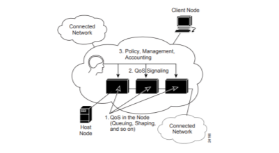
Fig- QOS Architecture
TCP is a transport layer protocol Transport layer protocols are typically designed for fixed wired networks.
We have already seen in TCP congestion control that packet loss in fixed network is typically due to overload situation. Routers discard the packets as soon as the receiving buffers are full. TCP indirectly recognizes congestion by missing acknowledgements.
Retransmission of packets only results in the addition to congestion. TCP reacts to this situation with slow start algorithm.
Influences of mobility on TCP
TCP assumes congestion if packets are dropped.
In wireless networks, packet loss is often due to transmission errors. Mobility itself can cause packet loss.
A mobile node roams from one access point to another while there are still packets in transit to the wrong access point.
On the other hand, TCP cannot be changed fundamentally due to the large base of installation in a fixed network. The basic TCP mechanism keeps the whole Internet together.
TCP for Wireless Network Indirect TCP I Indirect TCP or I TCP is based on segmenting the connection.
This is optimized TCP protocol for mobile hosts.
There are no changes to the TCP protocol for hosts connected to the wired network. There is no real end to end connection however splitting of TCP connection into two TCP connections takes place at the access point.

Hosts in the fixed part of the network do not notice the characteristics of the wireless point. Socket and state migration in I TCP takes place as shown in following Fig.
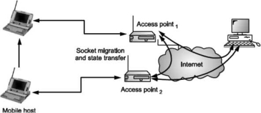
Fig. Socket and state migration in I TCP
Indirect TCP II With indirect TCP II all current optimizations to TCP still work. No changes in the fixed network are required. Transmission errors on the wireless link do not propagate into the fixed network.
This is mechanism is also simple to control as mobile TCP is used only for one hop, between a foreign agent and mobile host.
Hence very fast transmission of packets is possible.
However, with Indirect TCP II, there could be loss of end-to-end semantics as acknowledgement to a sender does not any longer mean that receiver really got a packet.
Also, higher latency is possible due to buffering of data within the foreign agent and forwarding the same to new foreign agent.
Snooping TCP I
Transparent extensions of TCP within the foreign agent. Snooping TCP I is about the buffering of packets sent to the mobile host Packets lost on the wireless links will be retransmitted immediately by the mobile host or foreign agent. This is called as local retransmission.
The foreign agent therefore snoops the packet flow and recognizes acknowledgements in both directions.
Change of TCP is only within the foreign agent. All other semantics of TCP are preserved.

End-to-end TCP connection
Fig. Snooping TCP I
Snooping TCP II
Snooping TCP II is designed to handle following two cases: Data transfer to the mobile host Data transfer from the mobile host In case ‘a’, foreign agent buffers the data until it receives acknowledgement from the mobile host. Foreign agent detects packet loss via duplicated acknowledgements or time out In case ‘b’, foreign agent detects the packet loss on the wireless link via sequence numbers and answers directly with ‘not acknowledged’ to the mobile host.
Mobile host can now retransmit data with only a very short delay. This mechanism maintains end to end semantics Also there are no major state transfers are involved during handover. Selective retransmission with TCP acknowledgements are often cumulative.
‘ACKNOWLEDGEMENT n,, acknowledges correct and in-sequence receipt of packets up to n.
If simple packets are missing quite often a whole packet sequence beginning at the gap has to be retransmitted, thus wasting bandwidth. Selective retransmission is one possible over it. RFC2018 allows for acknowledgements of single packets. This makes it possible for sender to retransmit only the missing packets. Much higher efficiency can be achieved with selective retransmission.
Transaction oriented TCP (T-TCP)
T-TCP is also aimed to achieve higher efficiency.
Normally there are 3 phases in TCP: connection setup, data transmission and connection release. So, 3-way handshake needs 3 packets for setup and release respectively. Even short messages need minimum of 7 packets. RFC 1644 describes T-TCP to avoid the overhead. With T-TCP connection setup, data transfer and connection release can be combined.
Thus only 2 or 3 packets are needed.
Introduction
The Network layer protocols are largely concerned with finding a path through the network from a source host to a destination host.
The Network layer doesn't provide an interface for application processes.
Above the Network layer is the Transport layer. The Transport layer provides an application process interface for actually connecting one process to another via the underlying network.
The goal of the Transport layer is application processes should communicate without needing to consider the network technology.
The Transport layer is an important layer in the protocol stack and perhaps the only layer seen by the ordinary users of the network. It is like an outer skin of the network which hides all the organs and functions of the network.
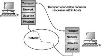
Its main task is to provide reliable connection from a network application running on a source computer to its corresponding application running on the destination computer.
The connection could be both connectionless and connection-oriented.
The OSI model specifies the Transport layer as providing only connection-oriented services. In TCP/IP standards, the Transport layer has provision for both connectionless and connection-oriented services.
Why transport layer is used
The basic duties of the transport layer is to accept data/message from the application (such as email application) which is running on the application layer. Transport layer then splits the received data/message into smaller units if needed.
It then passes these smaller data units (TPDU) to the network layer and ensures that the pieces all arrive correctly at the other end. But before sending the data units to network layer, transport layer adds transport layer header in front of each data unit.
Transport layer header prominently contains source & destination port numbers as well as sequence numbers. The transport layer is a true end-to-end layer, all the way from the source to the destination.
In other words, a program on the source machine carries on a conversation with a similar program on the destination machine, using the message headers and control messages. Transport layer provides end to end flow control and error control.
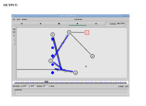
To implement a Transport Control Protocol in sensor network through the simulator.
SOFTWARE REQUIREMENTS: Network Simulator -2
THEORY: The Transmission Control Protocol (TCP) is one of the main protocols of the Internet protocol suite. It originated in the initial network implementation in which it complemented the Internet Protocol (IP). Therefore, the entire suite is commonly referred to as TCP/IP. TCP provides reliable, ordered, and error-checked delivery of a stream of octets (bytes) between applications running on hosts communicating by an IP network. Major Internet applications such as the World Wide Web, email, remote administration, and file transfer rely on TCP.
Applications that do not require reliable data stream service may use the User Datagram Protocol (UDP), which provides a connectionless datagram service that emphasizes reduced latency over reliability.
ALGORITHM:
1. Create a simulator object
2. Define different colors for different data flows
3. Open a nam trace file and define finish procedure then close the trace file, and execute nam on trace file.
4. Create six nodes that forms a network numbered from 0 to 5
5. Create duplex links between the nodes and add Orientation to the nodes for setting a LAN topology
6. Setup TCP Connection between n (0) and n (4)
7. Apply FTP Traffic over TCP
8. Setup UDP Connection between n (1) and n (5)
9. Apply CBR Traffic over UDP.
10. Schedule events and run the program.
PROGRAM:
Set ns [new Simulator]
#Define different colors for data flows (for NAM)
$ns color 1 Blue
$ns color 2 Red
#Open the Trace files
Set file1 [open out.tr w]
Set winfile [open WinFile w]
$ns trace-all $file1
#Open the NAM trace file
Set file2 [open out.nam w]
$ns namtrace-all $file2
#Define a 'finish' procedure
Proc finish {} {
Global ns file1 file2
$ns flush-trace
Close $file1
Close $file2
Exec nam out.nam &
Exit 0
}
#Create six nodes
Set n0 [$ns node]
Set n1 [$ns node]
Set n2 [$ns node]
Set n3 [$ns node]
Set n4 [$ns node]
Set n5 [$ns node]
$n1 color red
$n1 shape box
#Create links between the nodes
$ns duplex-link $n0 $n2 2Mb 10ms DropTail
$ns duplex-link $n1 $n2 2Mb 10ms DropTail
$ns simplex-link $n2 $n3 0.3Mb 100ms DropTail
$ns simplex-link $n3 $n2 0.3Mb 100ms DropTail
Set lan [$ns newLan "$n3 $n4 $n5" 0.5Mb 40ms LL Queue/DropTail MAC/Csma/Cd Channel]
#Setup a TCP connection
Set tcp [new Agent/TCP/Newreno]
$ns attach-agent $n0 $tcp
Set sink [new Agent/TCPSink/DelAck]
$ns attach-agent $n4 $sink
$ns connect $tcp $sink
$tcp set fid_ 1
$tcp set window_ 8000
$tcp set packetSize_ 552
#Setup a FTP over TCP connection
Set ftp [new Application/FTP]
$ftp attach-agent $tcp
$ftp set type_ FTP
$ns at 1.0 "$ftp start"
$ns at 124.0 "$ftp stop"
# next procedure gets two arguments: the name of the
# tcp source node, will be called here "tcp",
# and the name of output file.
Proc plotWindow {tcpSource file} {
Global ns
Set time 0.1
Set now [$ns now]
Set cwnd [$tcpSource set cwnd_]
Set wnd [$tcpSource set window_]
Puts $file "$now $cwnd"
$ns at [expr $now+$time] "plotWindow $tcpSource $file" }
$ns at 0.1 "plotWindow $tcp $winfile"
$ns at 5 "$ns trace-annotate \"packet drop\""
# PPP
$ns at 125.0 "finish"
$ns run
Conclusion:
References:
1. Kurose, Ross, “Computer Networking a Top Down Approach Featuring the Internet”, Pearson, ISBN-10: 0132856204
2. L. Peterson and B. Davie, “Computer Networks: A Systems Approach”, 5th Edition, Morgan-Kaufmann, 2012.
3. Douglas E. Comer & M.S Narayanan, “Computer Network & Internet”, Pearson Education
4. William Stallings, “Cryptography and Network Security: Principles and Practice”, 4th Edition
5. Pachghare V. K., “Cryptography and Information Security”, 3rd Edition, PHI