Unit - 2
Digital Modulation-I
Probability of Error defines average probability of error that can occur in a communication system.
Error Functions
(1) Error function erf(u):

(2) Complementary error function erfc(u):

Properties of Error function
1. Erf(-u) = -erf(u) - Symmetry.
2. Erf(u) approaches unity as u tends towards infinity.

3. For a Random variable X, with mean mx and variance σx2, the probability of X is defined by

Note: Relation: erfc(u) = 1 – erf(u) Tables are used to find these values.
Approximate value

Q – Function:
An alternate form of error function. It basically defines the area under the Standardized Gaussian tail. For a standardized Gaussian random variable X of zero mean and unit variance, the Q-function is defined by

Relations between Q-function and erfc function:


An optimum filter is such a filter used for acquiring a best estimate of desired signal from noisy measurement. It is different from the classic filters. These filters are optimum because they are designed based on optimization theory to minimize the mean square error between a processed signal and a desired signal, or equivalently provides the best estimation of a desired signal from a measured noisy signal.
It is pervasive that when we measure a (desired) signal d(n), noise v(n) interferes with the signal so that a measured signal becomes a noisy signal
x(n) x(n)=d(n)+v(n)
It is also very common that a signal d(n) is distorted in its measurement (e.g., an electromagnetic signal distorts as it propagates over a radio channel). Assuming that the system causing distortion is characterized by an impulse response of h (n) s, the measurement of d(n) can be expressed by the sum of distorted signal s(n) and noise
v(n) x(n)=s(n)+v(n)= h (n)∗ s d(n)+v(n)
Where s(n)= h (n)∗ s d(n).
If both d(n) and v(n) are assumed to be wide-sense stationary (WSS) random processes, then x(n) is also a WSS process. The signals that we discuss in this chapter will be WSS if they are not specially specified. If signal d(n) and measurement noise v(n) are assumed to be uncorrelated (this is true in many practical cases), then r (k) = r (k) = 0.
In this case, the noisy signal,
x(n)= h (n)∗ s d(n)+v(n),
The relation of r (k) x with r (k) d and r (k) v (the autocorrelations of x(n), d(n) and v(n), respectively) as follows,


For the noisy signal of the form x(n)= d(n)+v(n), a special case of where h (n) s =δ (n) and no distortion happens to d(n) in its measurement, we have


Optimum filtering is to acquire the best linear estimate of a desired signal from a measurement. The main issues in optimal filtering contain
• Filtering that deals with recovering a desired signal d(n) from a noisy signal (or measurement) x(n);
• Prediction that is concerned with predicting a signal d(n+m) for m>0 from observation x(n);
• Smoothing that is an a posteriori form of estimation, i.e., estimating d(n+m) for m

Fig 1 Optimum Filtering
Key takeaway
An optimum filter is such a filter used for acquiring a best estimate of desired signal from noisy measurement. It is different from the classic filters.
GENERATION AND COHERENT DETECTION OF BPSK SIGNALS
(i) Generation
To generate the BPSK signal, we build on the fact that the BPSK signal is a special case of DSB-SC modulation. Specifically, we use a product modulator consisting of two components.
(i) Non-return-to-zero level encoder, whereby the input binary data sequence is encoded in polar form with symbols 1 and 0 represented by the constant-amplitude.
(ii) Product modulator, which multiplies the level encoded binary wave by the sinusoidal carrier of amplitude to produce the BPSK signal. The timing pulses used to generate the level encoded binary wave and the sinusoidal carrier wave are usually, but not necessarily, extracted from a common master clock.
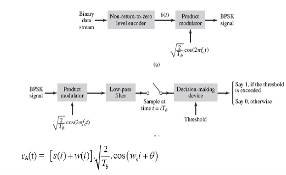
Fig. 2: Generation of BPSK Signal
(ii) Detection
To detect the original binary sequence of 1s and 0s, the BPSK signal at the channel output is applied to a receiver that consists of four sections
(a)Product modulator, which is also supplied with a locally generated reference signal that is a replica of the carrier wave
(b)Low-pass filter, designed to remove the double-frequency components of the product modulator output (i.e., the components centered on) and pass the zero-frequency components.
(c)Sampler, which uniformly samples the output of the low-pass filter at where; the local clock governing the operation of the sampler is synchronized with the clock responsible for bit-timing in the transmitter.
(d)Decision-making device, which compares the sampled value of the low-pass filters output to an externally supplied threshold, every seconds. If the threshold is exceeded, the device decides in favour of symbol 1; otherwise, it decides in favour of symbol 0. Levels.
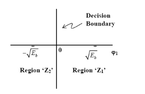
Fig. 3: Decision-making device
The signal at (B) is


Fig.4: Decision-making device
Error Calculation for BPSK
In BPSK system the basic function is given by

The signals S1(t) and S2(t) are given by
 =
= for symbol 1
 =-
=- for symbol 0
The signal space representation is as shown in fig (N=1 & M=2)
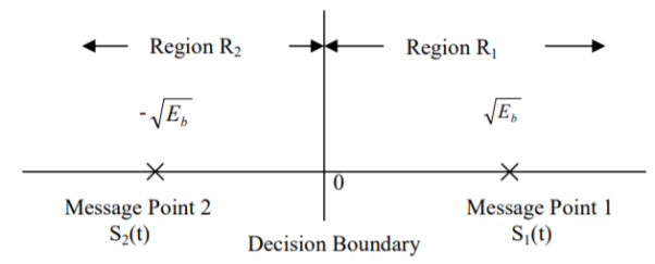
Fig.5 Signal Space Representation of BPSK
The observation vector x1 is related to the received signal x(t) by

If the observation element falls in the region R1, a decision will be made in favour of symbol ‘1’. If it falls in region R2 a decision will be made in favour of symbol ‘0’. The error is of two types
1) Pe (0/1) i.e., transmitted as ‘1’ but received as ‘0’ and
2) Pe (1/0) i.e., transmitted as ‘0’ but received as ‘1’. Error of 1st kind is given by
Therefore, the above equation becomes

Where =mean value = - for the transmission of symbol ‘0’
 for additive white Gaussiance noise.
Threshold value =0. [Indicates lower limit in integration]

Put 


The total probability of error Pe Pe (1/ 0) Pe (0) Pe (0 /1) Pe (1) assuming probability of 1’s and 0’s are equal.

GENERATION AND COHERENT DETECTION OF BFSK SIGNALS
(i) Generation
On-off level encoder:
Here, the output is of constant amplitude √Eb for input 1 and 0 for input 0.
Pair of oscillators:
Frequency f1 and f2 differ by integer multiple of 1/Tb. The lower oscillator has frequency f2 preceded by inverter. When in a signal interval, the input symbol is 1, the upper oscillator is switched on, and signal s1(t) is transmitted, while lower oscillator is switched off.
When input is 0, upper oscillator is off, lower oscillator is on and signal s2(t) is transmitted.
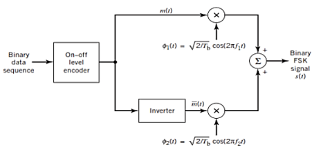
Fig.6: BFSK generation
(ii) Detection
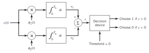
Fig.7: BFSK detection
It consists of two correlators with a common input, and reference signals Ø1(t), Ø2(t) are applied.
Then y = x1 – x2
The output y is compared with the threshold =0
If y>0 then output = 1 else 0.
But if y=0 then the receiver makes a random guess of 0 or 1.
Error Calculation
In binary FSK system the basic functions are given by


The transmitted signals S1(t) and S2(t) are given by
 for symbol 1
 for symbol 0
Therefore, Binary FSK system has 2-dimensional signal space with two messages S1(t) and S2(t), [N=2, m=2] they are represented as shown in figure
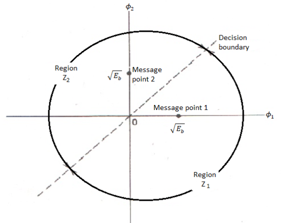
Fig.8 Signal Space diagram of Coherent binary FSK system.
The two message points are defined by the signal vector
 and
and 
The observation vector x1 and x2 (output of upper and lower correlator) are related to input signal x(t) as
 and
and 
Assuming zero mean additive white Gaussian noise with input PSD N0/2. With variance N0/2. The new observation vector ‘l’ is the difference of two random variables x1 & x2.
1 = x1 – x2
When symbol ‘1’ was transmitted x1 and x2 has mean value of 0 and √Eb respectively. Therefore, the conditional mean of random variable ‘l’ for symbol 1 was transmitted is

Similarly, for ‘0’ transmission

The total variance of random variable ‘l’ is given by
Var[l]= Var[x1] + Var[x2] No
The probability of error is given by


Similarly,

The total probability of error =

Assuming 1’s & 0’s with equal probabilities


Key Takeaways:
The FSK modulator block diagram comprises of two oscillators with a clock and the input binary sequence
The main methods of FSK detection are asynchronous detector and synchronous detector.
GENERATION AND COHERENT DETECTION OF QPSK SIGNALS
(i) Generation
The QPSK Modulator uses a bit-splitter, two multipliers with local oscillator, a 2-bit serial to parallel converter, and a summer circuit.
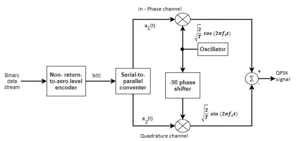
Fig.9: QPSK generation
At the modulator’s input, the message signal’s even bits (i.e., 2nd bit, 4th bit, 6th bit, etc.) and odd bits (i.e., 1st bit, 3rd bit, 5th bit, etc.) are separated by the bits splitter and are multiplied with the same carrier to generate odd BPSK (called as PSKI) and even BPSK (called as PSKQ). The PSKQ signal is anyhow phase shifted by 90° before being modulated.
The QPSK waveform for two-bits input is as follows, which shows the modulated result for different instances of binary inputs.
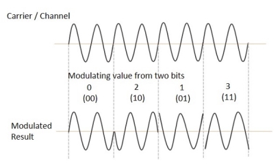
(ii) Detection
The QPSK Demodulator uses two product demodulator circuits with local oscillator, two band pass filters, two integrator circuits, and a 2-bit parallel to serial converter.
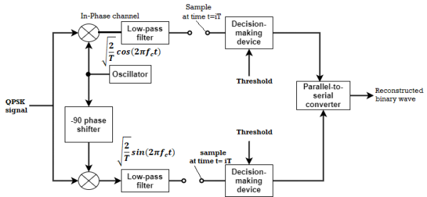
Fig.10: QPSK detectors
The two product detectors at the input of demodulator simultaneously demodulate the two BPSK signals. The pair of bits are recovered here from the original data. These signals after processing are passed to the parallel to serial converter.
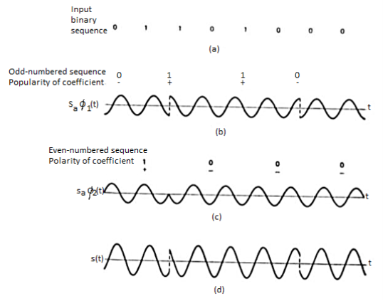
Fig.11: QPSK output
Error Calculation
In QPSK system the information carried by the transmitted signal is contained in the phase. The transmitted signals are given by


Where the carrier frequency fc=nc/7 for some fixed integer nc.
E = the transmitted signal energy per symbol.
T = Symbol duration.
The basic functions ɸ1(t) and ɸ2(t) are given by


There are four message points and the associated signal vectors are defined by
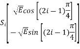
The table shows the elements of signal vectors, namely Si1 & Si2
Input dibit | Phase of QPSK signal (radians) | Coordinates of message points | Input dibit |
 |  | ||
10 |  |  |  |
00 |  |  |  |
01 |  |  | +  |
11 |  |  | +  |
Therefore, a QPSK signal is characterized by having a two-dimensional signal constellation (i.e., N=2) and four message points (i.e., M=4) as illustrated in figure.
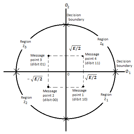
Fig 12. Signal-space diagram of coherent QPSK system
A QPSK system is in fact equivalent to two coherent binary PSK systems working in parallel and using carriers that are in-phase and quadrature. The in-phase channel output x1 and the Q-channel output x2 may be viewed as the individual outputs of the two coherent binary PSK systems. Thus, the two binary PSK systems may be characterized as follows
The signal energy per bit √E/2
The noise spectral density is No/2
The average probability of bit error in each channel of the coherent QPSK system is 


The bit errors in the I-channel and Q-channel of the QPSK system are statistically independent. The I-channel makes a decision on one of the two bits constituting a symbol (di bit) of the QPSK signal and the Q-channel takes care of the other bit. Therefore, the average probability of a direct decision resulting from the combined action of the two channels working together is pc= probability of correct reception p1= probability of error


The average probability of symbol error for coherent QPSK is given by

In the region where E/2No We may ignore the second term and so the approximate formula for the average probability of symbol error for coherent QPSK system is

Key takeaway
QPSK Modulator uses a bit-splitter, two multipliers with local oscillator, a 2-bit serial to parallel converter, and a summer circuit.
Minimum Shift Key Modulation is another type of digital modulation technique used to convert a digital signal into analog signals. It is also called Minimum-shift keying (MSK) or Advance Frequency Shift Keying because it is a type of continuous-phase frequency-shift keying.
Key features
- It is encoded with bits alternating between quadrature components, with the Q component delayed by half the symbol period.
- Minimum Shift Keying is the most effective digital modulation technique. It can be implemented for almost every stream of bits much easier than the Phase Shift Key, Frequency Shift Key and Amplitude Shift Key of digital modulation technique.
- The Minimum Shift Keying's concept is based on the positioning of bits such as even bits and odd bits for the given bitstream and the bit positioning frequency generating table.
- MSK is the most widely used digital modulation technology because of its ability and flexibility to handle "One (1)" and "Zero (0)" transition of binary bits.
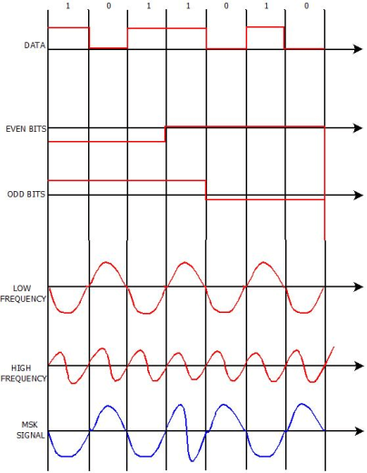
Fig.13: MSK output
The word binary represents two bits. M represents a digit that corresponds to the number of conditions, levels, or combinations possible for a given number of binary variables.
This is the type of digital modulation technique used for data transmission in which instead of one bit, two or more bits are transmitted at a time. As a single signal is used for multiple bit transmission, the channel bandwidth is reduced.
M-ary Equation
If a digital signal is given under four conditions, such as voltage levels, frequencies, phases, and amplitude, then M = 4.
The number of bits necessary to produce a given number of conditions is expressed mathematically as
N=log2M
Where
N is the number of bits necessary
M is the number of conditions, levels, or combinations possible with N bits.
The above equation can be re-arranged as
2N=M
For example, with two bits, 22 = 4 conditions are possible.
M-ary PSK
This is called as M-ary Phase Shift Keying M−ary PSK
The phase of the carrier signal, takes on M different levels.
Representation of M-ary PSK
Si(t)=√2E/T cos(wot+ϕit) 0≤t≤T and i=1,2...M
ϕi(t)=2πiM where i=1,2,3......M
Some prominent features of M-ary PSK are −
- The envelope is constant with more phase possibilities.
- This method was used during the early days of space communication.
- Better performance than ASK and FSK.
- Minimal phase estimation error at the receiver.
- The bandwidth efficiency of M-ary PSK decreases and the power efficiency increases with the increase in M.
So far, we have discussed different modulation techniques. The output of all these techniques is a binary sequence, represented as 1s and 0s
Error Calculation
In M-ary PSK, M different phase shifts of the carrier are used to convey the information. The M = 2k signal waveforms, each representing k information bits, are represented as


The M-ary PSK signal

By choosing the same basis functions as for QPSK, it is possible to express all waveforms in the M-PSK signal set as vectors in the plane spanned by φ1 and φ2 as

Where


The signal vectors lie around a circle of radius √ Es The constellation for 8- PSK (M = 8) is shown in Figure
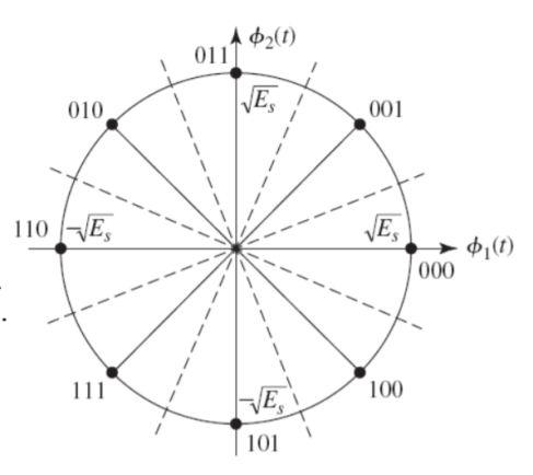
Fig 14 Signal space diagram for MSK system
The minimum distance between two adjacent signal points is

The nearest-neighbour estimate of Pe is


Key takeaway
The transmitted M number of signals are equal in energy and duration.
The signals are separated by 1/2Ts Hz making the signals orthogonal to each other.
Since M signals are orthogonal, there is no crowding in the signal space.
Modulation scheme | Distance | Bandwidth |
BPSK |  |  |
QPSK |  |  |
M-PSK |  |  |
16-QAM |  |  |
BFSK |  | (Orthogonal BFSK) |

N- number of bits per symbol


Solved Examples
Q1) Determine the baud and minimum bandwidth necessary to pass a 10-kbps binary signal using amplitude shift keying.
A1) For ASK, N = 1, and the baud and minimum bandwidth are determined from
B=fb/N
Where N is the number of bits encoded into each signaling element.
B = 10,000 / 1 = 10,000
Baud = 10, 000 /1 = 10,000
Q2) Determine (a) the peak frequency deviation, (b) minimum bandwidth, and (c) baud for a binary FSK signal with a mark frequency of 49 kHz, a space frequency of 51 kHz, and an input bit rate of 2 kbps.
A2)
a) Frequency deviation is ∆f = |fm – fs | / 2
Where ∆f = frequency deviation (hertz) |fm – fs | = absolute difference between the mark and space frequencies (hertz)
∆f = |149kHz - 51 kHz| / 2 =1 kHz
b. The minimum bandwidth is B = 2(∆f + fb)
Where B= minimum Nyquist bandwidth (hertz)
∆f= frequency deviation | (fm– fs) | (hertz)
Fb = input bit rate (bps)
B = 2(1000 + 2000) = 6 kHz c. For FSK, N = 1, and the baud is determined from Equation 2.11 as baud = 2000 / 1 = 2000
c. For FSK, N = 1, and the baud is determined from Equation 2.11 as baud = 2000 / 1 = 2000
Q3) For a BPSK modulator with a carrier frequency of 70 MHz and an input bit rate of 10 Mbps, determine the maximum and minimum upper and lower side frequencies, draw the output spectrum, determine the minimum Nyquist bandwidth, and calculate the baud.
A3) Substituting into Equation
BPSK output = [sin (2πfa t)] x [sin (2πfc t)]
Fa = fb / 2 = 5 MHz = [sin 2π(5MHz) t)] x [sin 2π(70MHz) t)] = 0.5cos [2π (70MHz – 5MHz) t] – 0.5cos [2π (70MHz + 5MHz) t]
Minimum lower side frequency (LSF): LSF=70MHz - 5MHz = 65MHz
Maximum upper side frequency (USF): USF = 70 MHz + 5 MHz = 75 MHz
Therefore, the output spectrum for the worst-case binary input conditions is as follows: The minimum Nyquist bandwidth (B) is
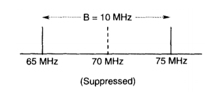
B = 75 MHz - 65 MHz = 10 MHz
And the baud = fb or 10 megabaud.
Q4) For the QPSK modulator shown in Figure, construct the truth table, phasor diagram, and constellation diagram.
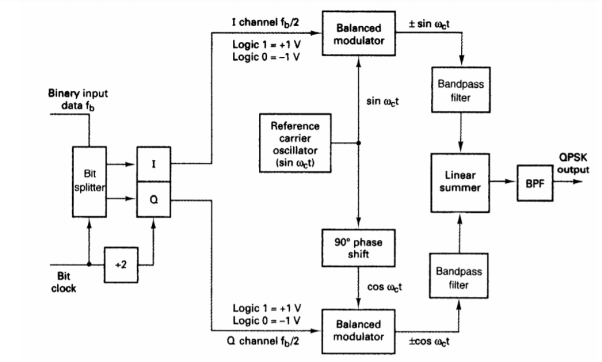
A4) For a binary data input of Q = O and I= 0, the two inputs to the I balanced modulator are -1 and sin ωc t, and the two inputs to the Q balanced modulator are -1 and cos ωc t.
Consequently, the outputs are
I balanced modulator = (-1) (sin ωc t) = -1 sin ωc t
Q balanced modulator = (-1) (cos ωc t) = -1 cos ωc t and
The output of the linear summer is -1 cos ωc t - 1 sin ωc t = 1.414 sin (ωc t - 135°)
For the remaining dibit codes (01, 10, and 11), the procedure is the same.
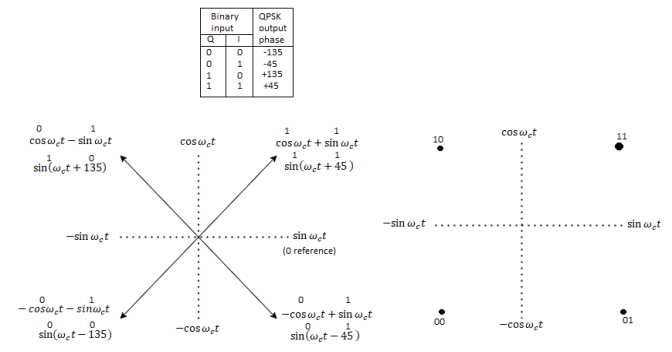
Fig QPSK modulator: (a) truth table; (b) phasor diagram; (c) constellation diagram
In Figures b and c, it can be seen that with QPSK each of the four possible output phasors has exactly the same amplitude. Therefore, the binary information must be encoded entirely in the phase of the output signal.
Figure b, it can be seen that the angular separation between any two adjacent phasors in QPSK is 90°. Therefore, a QPSK signal can undergo almost a+45° or -45° shift in phase during transmission and still retain the correct encoded information when demodulated at the receiver. Figure shows the output phase-versus-time relationship for a QPSK modulator.

Fig Output phase-versus-time relationship for a PSK modulator.
Q5) For a QPSK modulator with an input data rate (fb) equal to 10 Mbps and a carrier frequency 70 MHz, determine the minimum double-sided Nyquist bandwidth (fN) and the baud.
A5) The bit rate in both the I and Q channels is equal to one-half of the transmission bit rate, or
fbQ = fb1 = fb / 2 = 10 Mbps / 2 = 5 Mbps
The highest fundamental frequency presented to either balanced modulator is
Fa= fbQ / 2 = 5 Mbps / 2 = 2.5 MHz
The output wave from each balanced modulator is
(sin 2πfa t) (sin 2πfc t)
0.5 cos 2π (fc – fa) t – 0.5 cos 2π (fc + fa) t
0.5 cos 2π [(70 – 2.5) MHz]t – 0.5 cos 2π [(70 – 2.5) MHz]t
0.5 cos 2π(67.5MHz) t - 0.5 cos 2π(72.5MHz) t
The minimum Nyquist bandwidth is B= (72.5-67.5) MHz = 5MHz
The symbol rate equals the bandwidth: thus, symbol rate = 5 megabaud
Q6) For an 8-PSK system, operating with an information bit rate of 24 kbps, determine (a) baud, (b) minimum bandwidth, and (c) bandwidth efficiency.
A6)
a. Baud is determined by
Baud = 24 kbps / 3 = 8000
b. Bandwidth is determined by
B = 24 kbps / 3 = 8000
c. Bandwidth efficiency is calculated
Bη = 24, 000 / 8000 = 3 bits per second per cycle of bandwidth
Q7) For a QPSK system and the given parameters, determine a. Carrier power in dBm. b. Noise power in dBm. c. Noise power density in dBm. d. Energy per bit in dBJ. e. Carrier-to-noise power ratio in dB. f. EblNo ratio. C = 10-12 W, Fb = 60 kbps, N = 1.2 x 10 -14W, B = 120 kHz
A7) a. The carrier power in dBm is determined by
C = 10 log (10 -12 / 0.001) = - 90 dBm
b. The noise power in dBm is determined by
N = 10 log [(1.2x10⁻¹⁴) / 0.001] = -109.2 dBm
c. The noise power density is determined by
No = -109.2 dBm – 10 log 120 kHz = -160 dBm d.
The energy per bit is determined by Eb = 10 log (10-12 / 60 kbps) = -167.8 dBJ
e. The carrier-to-noise power ratio is determined by
C / N = 10 log (10-12 / 1.2 x 10⁻¹⁴) = 19.2 dB
f. The energy per bit-to-noise density ratio is determined by
Eb / No = 19.2 + 10 log 120 kHz / 60 kbps = 22.2 dB
Q8) Determine the minimum bandwidth required to achieve a P(e) of 10-7 for an 8-PSK system operating at 10 Mbps with a carrier-to noise power ratio of 11.7 dB.
A8) The minimum bandwidth is
B / fb = Eb / No = C / N = 14.7 dB – 11.7 dB = 3 dB
B / fb = antilog 3 = 2
B = 2 x 10 Mbps = 20 MHz
Q9) We need to send data 3 bits at a time at 9 bit rate of 3mbps. The carrier frequency is 10MHz. Calculate the number of levels the baud rate and bandwidth?
A9) n= 3 bits
R= 3Mbps
fc= 10MHz
L=2n = 23=8
The number of levels =8
Baud rate = Bit rate/n= 3Mpbs/3 =1Mbaud
Bandwidth = L*r=8*1Mbaud= 8MHz
Q10) We have an available bandwidth of 100kHz which spans from 200- 300kHz. What should be the carrier frequency and the bit rate if we modulated the data by using FSK?
A10)
Q


Q11) A voice signal is sampled at the rate of 8000 samples/sec and each sample is encoded in to 8 bits using PCM. The binary data is transmitted into free space after modulation. Determine the bandwidth of modulated signal, if the modulation technique is ASK, FSK, PSK for f1 =10MHz, f2= 8MHz?
A11)
Bit rate 
Baud rate=8000 samples/sec
No. Of bits per sample =8

Band width of A
Band width of 
Band width of 


Q12) Find the maximum bit rates of an FSK signal in bps, if the bandwidth of the medium is 12 kHz and the difference between the two carriers is 2 kHz (given that transmission mode is full duplex)
A12) As transmission is full duplex only 6kHz is allotted for each direction.
Bandwidth = 2Bit Rate + fc1-fc0
2Bit Rate= Bandwidth – (fc1-fc0) =6000-2000=4000
Bit rate= 2000bps
Q13) A BPSK modulator has a carrier frequency of 70MHz and an input bit rate of 10Mbps. Calculate the maximum upper side band frequency in MHz?
A13)

 is maximum fundamental frequency of binary input
 is input bit rate
 is reference carrier frequency
The output of a BPSK modulator with carrier frequency of 70 MHz and bit rate of 10 Mbps is


Therefore, the maximum upper sideband frequency

Q14) In digital communication channel employing FSK, the 0 and 1 bits are represented by sine waves of 10kHz and 25kHz respectively. These waveforms will be orthogonal for a bit interval of?
A14)
For orthogonality of two sine waves in  duration there should be integral multiple of cycles of both sine wave.
Time period of first sine wave

Time period of the second sine wave

Therefore, 200s is the integral multiple of both  and
and  . Hence the two given waveforms will be orthogonal for a bit interval of 200s.
Q15) Find the minimum bandwidth (in kHz) required for transmitting an ASK signal at 2 kbps in half duplex transmission mode.
A15) In ASK, the baud rate and bit rate are the same. Therefore, baud rate is 2000 bauds. An ASK signal requires a minimum bandwidth equal to its baud rate. Therefore, minimum bandwidth = 2000 Hz = 2 kHz
Q16) A communication system employs ASK to transmit a 10 kbps binary signal. Find the baud rate required in bauds.
A16) For an ASK system, the minimum bandwidth is the same as the bit rate of the signal. Therefore, minimum bandwidth = 10000 Hz
Q17) For the data given in the above Question, find the minimum bandwidth required in hertz
A17) For an ASK system, the minimum bandwidth is the same as the bit rate of the signal. Therefore, minimum bandwidth = 10000 Hz
Q18) Determine the peak frequency deviation, for a binary FSK signal with a mark frequency of 51 kHz, a space frequency of 49 kHz, and an input bit rate of 2.
A18) The peak frequency deviation is ∆f = (mark frequency-space frequency)/2 =|49kHz - 51 kHz| / 2 =1 kHz kbps.
Q19) Determine minimum bandwidth for a binary FSK signal with a mark frequency of 51 kHz, a space frequency of 49 kHz, and an input bit rate of 2.
A19) minimum bandwidth = 2(  + 2Rb) = 2(1+2) =6K
References:
1. “Communication Systems”, Simon Haykin, Wiley publication, 4th Edition, 2004
2. “Digital Communication Fundamentals and Applications”, Bernard Sklar, Pearson Education India, 2nd Edition, 2009
3. “Modern Electronic Communication”, Miller Gary M, Prentice-Hall, 6th Edition, 1999
4. “Digital Communications”, John Proakis, Tata Mc Graw hill, 5th Edition, 2007
5. “Electronic Communication Systems, Fundamentals Through Advanced”, Wayne Tomsi, Pearson Education, 4th Edition, 2001
6. Communication systems by B.P. Lathi