Unit - 4
Spread Spectrum Modulation

Fig.1: General spread spectrum structure
- Spread spectrum is specially used for wireless communication signal spreading. Transmitted signals frequency varies deliberately.
- Frequency hopping and direct sequence are two popular spread spectrums.
- In frequency hopping, signals are broadcast over any random series of frequency while in direct sequence each bit is in order of multiple bit of transmitting signal it uses chipping code.
Spread spectrum signals are used for
- Combating or suppressing the detrimental effects of interference due to jamming (Intentional interference). It can be used in military applications also.
- Accommodating multiple users to transmit messages simultaneously over the same channel bandwidth. This type of digital communication in which each user (transmitter-receiver pair) has a distinct PN code for transmitting over a common channel bandwidth is called as Code Division Multiple Access (CDMA) or Spread Spectrum Multiple Access (SSMA). This technique is popularly used in digital cellular communications.
- Reducing the unintentional interference arising from other users of the channel.
- Suppressing self-interference due to multipath propagation.
- Hiding a signal by transmitting it at low power and, thus, making it difficult for an unintended listener to detect in the presence of background noise. It is also called a Low Probability of Intercept (LPI) signal.
- Achieving message privacy in the presence of other listeners.
- Obtaining accurate range (time delay) and range rate (velocity) measurements in radar and navigation.
Key takeaway
There are two spread-spectrum approaches called Transmitted Reference (TR) and Stored Reference (SR).
(i) In a TR system, the transmitter sends two versions of truly random spreading signal (wideband carrier) – one modulated by data and the other unmodulated. The receiver used the unmodulated carrier as the reference signal for despreading (correlating) the data modulated carrier.
(ii) (ii)In a SR system, the spreading code signal is independently generated at both the transmitter and the receiver. Since the same code must be generated independently at two locations, the code sequence must be deterministic, even though it should appear random to unauthorized listeners. Such random appearing deterministic signals are called pseudo noise (PN), or pseudorandom signals.
(iii) Modern spread spectrum systems use Stored Reference (SR) approach which uses a Pseudo noise (PN) or pseudorandom code signal.
Direct Sequence Spread Spectrum (DSSS) using BPSK modulation, so the first reversing switch introduces 180 degree phase reversals according to a pseudo-random code, while the second introduces the same reversals to reconstitute the original, narrow-band signal. The output is a “recompressed” narrow-band signal.
DSSS is a spread spectrum modulation technique used for digital signal transmission over airwaves. It was originally developed for military use, and employed difficult-to-detect wideband signals to resist jamming attempts.
It is also being developed for commercial purposes in local and wireless networks.
The stream of information in DSSS is divided into small pieces, each associated with a frequency channel across spectrums. Data signals at transmission points are combined with a higher data rate bit sequence, which divides data based on a spreading ratio. The chipping code in a DSSS is a redundant bit pattern associated with each bit transmitted.
This helps to increase the signal's resistance to interference. If any bits are damaged during transmission, the original data can be recovered due to the redundancy of transmission.
The entire process is performed by multiplying a radio frequency carrier and a pseudo-noise (PN) digital signal. The PN code is modulated onto an information signal using several modulation techniques such as quadrature phase-shift keying (QPSK), binary phase-shift keying (BPSK), etc. A doubly-balanced mixer then multiplies the PN modulated information signal and the RF carrier. Thus, the TF signal is replaced with a bandwidth signal that has a spectral equivalent of the noise signal. The demodulation process mixes or multiplies the PN modulated carrier wave with the incoming RF signal. The result produced is a signal with a maximum value when two signals are correlated. Such a signal is then sent to a BPSK demodulator. Although these signals appear to be noisy in the frequency domain, bandwidth provided by the PN code permits the signal power to drop below the noise threshold without any loss of information.
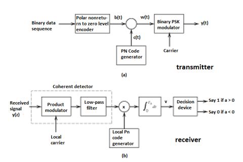
Fig 2(a) Transmitter (b) Receiver of DS-SS Technique

Fig 3 Wave forms for DSSS
Key takeaway
- In practice, the transmitter and receiver of Figures shown above are followed. In the transmitter spectrum spreading is performed prior to phase modulation. Also phase demodulation is done first and then despreading is done second, in the receiver.
- In the model of DS spread spectrum BPSK system used for analysis, the order of these two operations is interchanged. In the transmitter, BPSK is done first and spectrum spreading is done subsequently. Similarly, at the receiver also, spectrum de spreading is done first and then phase demodulation is done second.
- This is possible, because the spectrum spreading and BPSK are both linear operations.
The most important application of spread spectrum technique is the Digital cellular CDMA system. Here, we shall explain in detail about this CDMA digital cellular system based on Direct Sequence (DS) spread spectrum. This digital cellular communication system was proposed and developed by Qualcomm corporation. It has been standardized and designated as Interim Standard 95 (IS-95) by the Telecommunications Industry Association (TIA) for use in the 800 MHz and in the 1900 MHz frequency bands. The nominal bandwidth used for transmission from a base station to the mobile receivers (Forward link or channel) is 1.25 MHz. A separate channel, also with a bandwidth of 1.25 MHz is used for signal transmission from mobile receivers to a base station (reverse link or channel). The signals transmitted in both the forward and reverse links are DS Spread spectrum signals having a chip rate of 1.288 x 10⁶ chips per second (Mchips/s).
A) Forward link or channel
The signal transmission from a base station to the mobile receivers is referred as the Forward link or channel. The figure below shows the block diagram of IS-95 forward link.
Source coding
The speech (source) coder is a code-excited linear predictive (CELP) coder. It generates data at the variable rates of 9600, 4800, 2400 and 1200bits/s. The data rate is a function of the speech activity of the user, in frame intervals of 20ms.
Channel coding
The data from the speech coder is encoded by a rate 1/2, constraint length K = 9 convolutional code. For lower speech activity, the output symbols from the convolutional encoder are repeated. If the data rate is 4800 bits/s, then the output symbols are repeated twice, so as to maintain a constant bit rate of 9600 bits/s.
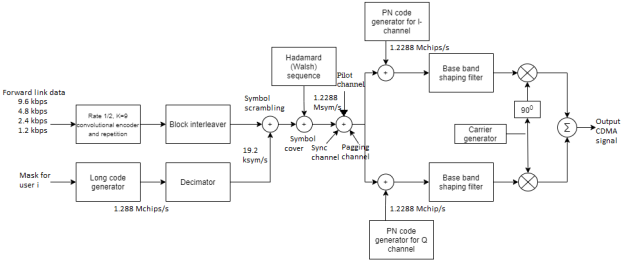
Fig 4 IS-95 Forward Link
Block interleaver:
The encoded bits for each frame are passed through a block interleaver. It is needed to overcome the effects of burst errors that may occur in transmission through the channel. The data bits at the output of the block interleaver occur at a rate of 19.2kbits/s.
Symbol scrambler
The data bits from the block interleaver are scrambled by multiplication with the output of a long code (period N=242 -1) generator. This generator is running at the chip rate of 1.288M chips/s, but the output is decimated by a factor of 64 to 19.2 kchips/s. The long code is used to uniquely identify a call of a mobile station on the forward and reverse links.
Hadamard Sequence
Each user of the channel is assigned a Hadamard (or Walsh) sequence of length 64. There are 64 orthogonal Hadamard sequences assigned to each base station. Thus, there are 64 channels available. One Hadamard sequence is used to transmit a pilot signal. The pilot signal is used for measuring the channel characteristics, including the signal strength and the carrier phase offset. Another Hadamard sequence is used for providing time synchronization. Another one sequence may be used for messaging (paging) service. Hence there are 61 channels left for allocation to different-users. The data sequence is now multiplied by the assigned Hadamard sequence of each user.
Modulator
The resulting binary sequence is now spread by multiplication with two PN sequences of length 215 and rate 1.2288 Mchips/s. This operation creates in-phase and quadrature signal components. Thus, the binary data signal is converted to a four-phase signal. Then, both I and Q signals are filtered by baseband spectral shaping filters. Different base stations are identified by different offsets of these PN sequences. The signals for all the 64 channels are transmitted synchronously. Finally, heterodyning of a carrier wave with BPSK modulation and QPSK spreading, is done. The summed output is the CDMA signal.
Mobile receiver
At the receiver, a RAKE demodulator is used to resolve the major multipath signal components. Then, they are phase-aligned and weighted according to their signal strength using the estimates of phase and signal strength derived from the pilot signal. These components are combined and passed to the Viterbi Soft decision decoder.
B) Reverse link or channel
The signal transmission from mobile transmitters to a base station is referred as the Reverse link or channel. The Figure below shows the block diagram of IS-95 reverse link.
Limitations
In the reverse link, the signals transmitted from various mobile transmitters to the base station are asynchronous. Hence, there is significantly more interference among users. Also, the mobile transmitters are usually battery operated and therefore, these transmissions are power limited. We have to design the reverse link in order to compensate for these two limitations.
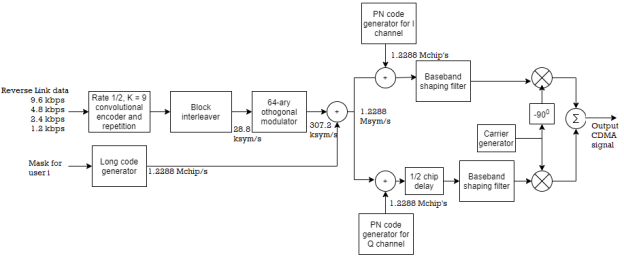
Fig 5 IS-95 Reverse link
Source coding
The reverse link data may also be at variable rates of 9600, 4800, 2400 and 1200 bits/s. The data rate is a function of the speech activity of the user, in frame intervals of 20ms.
Channel coding
The data from the speech coder is encoded by a rate 1/3, constraint length K=9 convolutional code. This coder has higher coding gain in a fading channel. This compensates for the above-mentioned limitations. For lower speech activity, the output bits form the convolutional encoder are repeated either two, or four, or eight times.
Block interleaver
The encoded bits for each frame are passed through a block interleaver. It is needed to overcome the effects of burst errors. For each 20ms frame, the 576 encoded bits are block-interleaved. However, the coded bit rate is 28.2 kbits/s.
Hadamard sequence
The data is modulated using an M=64 orthogonal signal set using Hadamard sequences of length 64. Thus, a 6-bit block of data is mapped into one of the 64 Hadamard sequences. The result is a bit (or chip) rate of 307.2 kbits/s at the output of the modulator.
Symbol scrambler
To reduce interference to other users, the time position of the transmitted code symbol repetitions is randomized. Hence, at the lower speech activity, consecutive bursts do not occur evenly spaced in time. The signal is also spread by the output of the long code generator running at a rate of 1.2288 Mchips/s. This is done for channelization (addressing), for privacy, scrambling, and spreading.
Modulator
The resulting 1.2288 Mchips/s binary sequence at the output of the multiplier is then further multiplied by two PN sequences of length N=215 with rate 1.2288 Mchips/s. This operation creates in phase and quadrature signals. Both the I and Q signals are filtered by baseband spectral shaping filters. The Q-channel signal is delayed in time by one half PN chip time relative to the I-channel signal prior to the base band filter. The signal at the output of the two baseband filters is an offset QPSK signal. Finally, the filtered signals are passed to quadrature mixers. The summed output is the CDMA signal.
Base station Receiver
The base station dedicates a separate channel in order to receive the transmissions of each active user in the cell. Although the chips are transmitted as an offset QPSK signal, the demodulator at the base station receiver employs noncoherent demodulation. A fast Hadamard transform is used to reduce the computational complexity in the demodulation process. The output of the demodulator is then fed to the Viterbi detector, whose output is used to synthesize the speech signal.
Key takeaway
Approach | SDMA | TDMA | FDMA | CDMA |
Idea | Segment space into cells/sectors | Segment sending time into disjoint time-slots, demand driven or fixed patters | Segment the frequency band into disjoint sub-bands | Spread the spectrum using orthogonal codes
|
Terminals | Only one terminal can be active in one cell/one sector | All terminals are active for short periods of time on the same frequency | Every terminal has its own frequency. Uninterrupted | All terminals can be active at the same place at the same moment uninterrupted. |
Signal separation | Cell structure, directed antennas | Synchronization in the time domain | Filtering in the frequency domain | Code plus special receivers |
Advantages | Very simple, increases capacity per km2 | Established, fully digital, flexible | Simple, established robust | Flexible, less frequency planning needed, soft handover |
Disadvantages | Inflexible, antennas typically fixed | Guard space needed (multipath propagation), synchronization difficult | Inflexible, frequencies are a scarce resource | Complex receivers, needs more complicated power control for senders |
Comment | Only in combination with TDMA, FDMA or CDMA useful | Standard in fixed networks, together with FDMA/SDMA used in many mobile networks | Typically combined with TDMA (frequency hopping patterns) and SDMA (frequency reuse) | Still faces some problems, higher complexity, lowered expectations: will be integrated with TDMA/FDMA |
The second widely used method is the direct-sequence spread spectrum ranging technique, as shown in figure below. This technique has been used in GPS C/A code and P code.

Fig:6 DS/SS System
The difference between DS/SS and CW ranging systems is that with DS/SS the carrier is phase-shift modulated by a pseudo-random signal. At the receiver, the received signal is demodulated. By measuring the number of chips of the code delay between the signals being transmitted and received, one can determine uniquely the range from the transmitter to the receiver.
The basic principle of PN ranging is the following. Two identical PN codes are involved. One code propagates between the transmitter and the receiver. The other code is maintained in the receiver. Since a PN code is completely deterministic, the sequence of ones and zeros in the code is completely known. Both codes are initiated in synchronism at a particular time, to. The code that propagates between the transmitter and the receiver is received by the receiver, delayed by the propagation time. The receiver then shifts the local version of the PN code, keeping track of the amount of time delay until its sequence exactly matches the sequence being received from the transmitter. When the receiver observes that the two versions of the same PN code are "matched" or synchronized at the observation time, tr,  T = tr - to is the range delay time.
The difference between DS/SS and CW ranging systems is that with DS/SS the carrier is phase-shift modulated by a pseudo-random signal. At the receiver, the received signal is demodulated. By measuring the number of chips of the code delay between the signals being transmitted and received, one can determine uniquely the range from the transmitter to the receiver. The basic principle of PN ranging is the folIowing. Two identical PN codes are involved. One code propagates between the transmitter and the receiver. The other code is maintained in the receiver. Since a PN code is completely deterministic, the sequence of ones and zeros in the code is completely known.
Both codes are initiated in synchronism at a particular time, to. The code that propagates between the transmitter and the receiver is received by the receiver, delayed by the propagation time. The receiver then shifts the local version of the PN code, keeping track of the amount of time delay until its sequence exactly matches the sequence being received from the transmitter. When the receiver observes that the two versions of the same PN code are "matched" or synchronized at the observation time, tr,  T = tr - to is the range delay time.
The matching of the local code with the received code is essentially matching the zero-one sequence and then "exactly" matching the leading and trailing edges of each chip with the sequence. Any error in time delay translates into an error in determining the range separating the transmitter and receiver. It is clear that the smaller the chip duration, the smaller the code matching error. The spread spectrum technique has its advantage in that its phase is easily resolved, as shown in figure below. By matching received PN code and the local PN code, a high time resolution can be achieved. If the repetition cycle of the PN code is long enough, the range between transmitter and the receiver cm be determined without ambiguity. The spread spectrum technique has the ability to discriminate interference signals.
A sharp correlation peak occurs when local PN code exactly matches the received PN code. The later correlation peaks due to multipath propagation are rejected. In addition, DS/SS systems minimize interference to other services in the same frequency band by transmitting at low power densities. For a spread spectrum system to operate properly, the received code must be synchronized with the transmitter code to within 1 chip. Range measurement is made by counting chips of offset or fractions of chips and is therefore a discrete measurement. In practice measurements are commonly made to within a fraction of a chip period. The highest-resolution spread spectrum systems known can measure range to approximately 1/1000th of a chip period.
Therefore, DS/SS ranging technique has its limitations when used in high-resolution ranging applications. The range resolution of a DS/SS ranging system depends on the chosen chip rate and accuracy of synchronization of the local PN code with the received PN code. For example, to design a DS/SS ranging system with range resolution of 5 centimetres, and assuming the accuracy of PN code synchronization of the transmitter and the receiver can discriminate to one-hundredth of a chip. The chip wavelength should be less than 5 meters (= 5 x 10-2 x 100), which gives a chip rate of:
Rc = c/ c= 2.997925x10⁸/5= 0.6x10⁸ cps
Where, c= speed of light
Rc = chip rate
 c= wavelength of chip
Obviously, the above result is impractical for the applications with lower carrier frequencies. Increasing the resolution of a DS/SS system requires increasing the chip rate or increasing synchronization accuracy of the system or both. Unfortunately, both methods are often limited by other factors in practical applications. Another limitation with DÇ/SS ranging systems is that only the phase resolvability of the modulating pseudorandom signals is used. The carrier phase information, which cm provide higher range resolution, is discarded.

Fig:7 DS/SS Correlation; N - Length of PN sequence, t1 - Chip duration
This is frequency hopping technique, where the users are made to change the frequencies of usage, from one to another in a specified time interval, hence called as frequency hopping. For example, a frequency was allotted to sender 1 for a particular period of time. Now, after a while, sender 1 hops to the other frequency and sender 2 uses the first frequency, which was previously used by sender 1. This is called as frequency reuse.
The frequencies of the data are hopped from one to another in order to provide a secure transmission. The amount of time spent on each frequency hop is called as Dwell time.
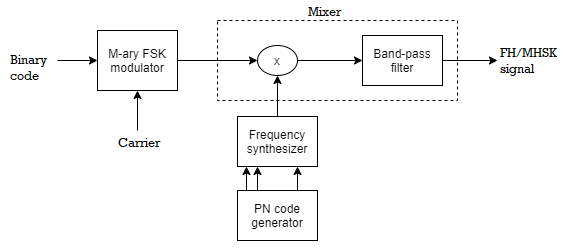
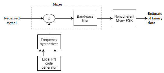
Fig 8 FHSS Transmitter and Receiver
Advantages of FH-SS system:
1. The processing gain PG is higher than that of DS-SS system
2. Synchronization is not greatly dependent on the distance.
3. The serial search system with FH-SS needs shorter time for acquisition.
Disadvantages of FH-SS system:
1. The bandwidth of FH-SS system is too large (in GHz).
2. Complex and expensive digital frequency synthesizers are required.
Applications of FHSS system:
1) CDMA systems based on FH spread spectrum signals are particularly attractive for mobile communication.
2) Wireless local area networks (WLAN) standard for Wi-Fi.
3) Wireless Personal area network (WPAN) standard for Bluetooth.
Comparison between FHSS and DSSS
FHSS | DSSS |
Multiple frequencies are used | Single frequency is used |
Hard to find the user’s frequency at any instant of time | User frequency, once allotted is always the same |
Frequency reuse is allowed | Frequency reuse is not allowed |
Sender need not wait | Sender has to wait if the spectrum is busy |
Power strength of the signal is high | Power strength of the signal is low |
Stronger and penetrates through the obstacles | It is weaker compared to FHSS |
It is never affected by interference | It can be affected by interference |
It is cheaper | It is expensive |
This is the commonly used technique | This technique is not frequently used |
- Pseudo-Noise (PN) also known Pseudo Random Binary Sequence (PRBS).
- A Pseudo-Noise code (PN-code) or Pseudo Random Noise Code (PRN code) is a spectrum which generated deterministically by random sequence.
- PN sequence is random occurrence of 0’s and 1’s bit stream.
- Directly sequence spread spectrum (DS-SS) system is most popular sequence in DS-SS system bits of PN sequence is known as chips and inverse of its period is known as chip rate.
In frequency hopping spread spectrum (FH-SS) sequence, channel number are pseudo random sequences and hop rate are inverse of its period.
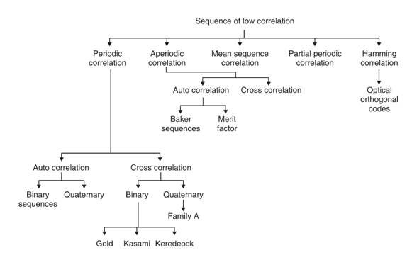
Fig.9: Overview of PN sequence
Properties
(i) Balance property:
Total no. Of 1’s is more than no. Of 0’s in maximum length sequence.
(ii) Run property 1’s and 0’s stream shows length sequence, every fraction relates some meaning.
Rum | Length |
1/2 | 1 |
1/4 | 2 |
1/8 | 3 |
(iii) Correlation property:
If compared sequences are found similar then it is auto correlation.
If compared sequences are found mismatched then it is cross correlation.
Let (K) and y (K) are two sequences then correlation R (m) will be:
R (m)xy= x (k) y (k + m)
Correlation R (m) in pattern of digital bit sequence will be:
R (m) =
y1 = P1 q1
y1 = 0 if P1 q1
y1 = 1 if P1 = q1

Fig 10: Correlator
Fig. Above shows Pi is a sequence which shifts through K bit shift register. K is length of correlate. Output achieved by K XNOR gate after comparison.
(iv) Shift and add:
By using X-OR gate, shift sequence modulo-2 added to upshifted sequence.
PN Sequence Generation
The class of sequences used in spread spectrum communications is usually periodic in that a sequence of 1s and 0s repeats itself exactly with a known period. The maximum length sequence, a type of cyclic code represents a commonly used periodic PN sequence. The maximum length sequences or PN sequences can be generated easily using shift register circuits with feedback from one or more stages. A PN sequence generator using a 3-stage shift register is shown in Figure below.
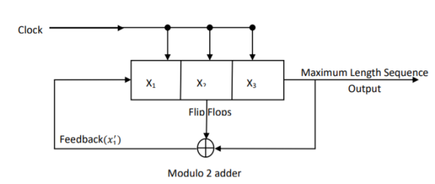
Fig 11 PN sequence or Maximum Length Sequence Generator
The 3-stage shift register consists of 3 flipflops regulated by a single timing clock. At each pulse of the clock, the state of each flipflop is shifted to the next one. The feedback function is obtained by using modulo-2 addition of the outputs of flipflops x2 and x3. The feedback term is applied to the input of the first flipflop x1. The maximum length sequence output is obtained by noting the contents of flipflop x3 at each clock pulse. The maximum-length sequence so generated is always periodic with a period of N = 2 m-1
Where m is the length of the shift register.
Here, m = 3 and so N = 23 -1 = 7. For the PN sequence generator of Figure above, if we assume that the shift register contents are initially 111, then with each clocking pulse, the contents will change as shown in the following table
Shifts |
 | Shift register contents | ||
 |  |  | ||
0 |
| 1 | 1 | 1 |
1 |  | 0 | 1 | 1 |
2 |  | 0 | 0 | 1 |
3 | 0  | 1 | 0 | 0 |
4 | 0  | 0 | 1 | 0 |
5 |  | 1 | 0 | 1 |
6 |  | 1 | 1 | 0 |
7 |  | 1 | 1 | 1 |
Hence for one period, the output PN sequence is 1 1 1 0 0 1 0, with a sequence length of 7. Thereafter, the sequence will be repeated.
Key takeaway
- The length of the PN sequence is N = 2m-1, where m is the number of shift register stages.
- The PN sequence repeats itself after every ‘N’ clock cycles.
- The PN sequence is an NRZ type pulse signal with logic l represented by + 1 and logic 0 represented by -1, as shown in Figure
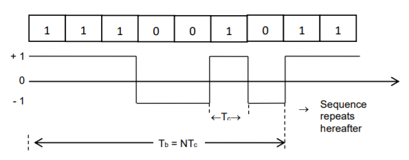
Fig 12 PN Sequence waveform
- The duration of every bit is known as the chip duration Tc. The chip rate Rc is defined as the number of bits (chips) per second. Tc = 1/𝑅𝑐 (or) Rc = 1 𝑇𝑐
- The period of the PN sequence is Tb = NTc
- The autocorrelation function R() is a periodic function of time and it is a two valued function.
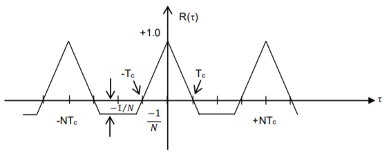
Fig 13 Autocorrelation function of a PN sequence
Example
Q1) A four stage shift register with feedback connections taken from the outputs of stages 4 and 1 through a modulo– 2adder, is used for PN sequence generation. Assuming the initial contents of the shift register to be 0100, determine the output sequence. What is the length of the sequence?
A1) The PN sequence generator is shown in Figure

Fig 14 PN Sequence Generator
If the initial contents of the shift register are 0100, then with each clocking pulse, the contents will change as shown in the following table
Shifts | Feedback
 | Shift register contents | |||
 |  |  |  | ||
0 |
| 0 | 1 | 0 | 0 |
1 |  | 0 | 0 | 1 | 0 |
2 |  | 0 | 0 | 0 | 1 |
3 | 0  | 1 | 0 | 0 | 0 |
4 | 0  | 1 | 1 | 0 | 0 |
5 |  | 1 | 1 | 1 | 0 |
6 |  | 1 | 1 | 1 | 1 |
7 |  | 0 | 1 | 1 | 1 |
8 | 1  | 1 | 0 | 1 | 1 |
9 | 1  | 0 | 1 | 0 | 1 |
10 | 1  | 1 | 0 | 1 | 0 |
11 | 0  | 1 | 1 | 0 | 1 |
12 | 1  | 0 | 1 | 1 | 0 |
13 | 0  | 0 | 0 | 1 | 1 |
14 | 1  | 1 | 0 | 0 | 1 |
15 | 1  | 0 | 1 | 0 | 0 |
The output PN sequence is 0 0 1 0 0 0 1 1 1 1 0 1 0 1 1 After 15 shifting’s, the initial contents of the shift registers are once again obtained. For further shifting’s, the same cycle of events will repeat. Thus, the length of one period of the PN sequence is, N = 2m – 1 = 24 – 1 = 15. Hence the sequence is a maximal length sequence.
Q2) A spread spectrum communication system is characterised by the following parameters Information bit duration, Tb = 4.095 ms PN chip duration, Tc = 1s Determine the processing gain and jamming margin if 𝑬𝒃/𝑵𝒐 =10 and the average probability of error, Pe=0.5 x 10⁻⁵.
A2)
i) the processing gain, PG

Hence PG=4095. Since PG=Spread factor, N, we have PG=N=4095
Ii) The jamming margin is


Need for Synchronization
The process in which the locally generated carrier at the receiver must be in frequency and phase synchronism with the carrier at the transmitter is called synchronization. In spread spectrum communication systems, there should be perfect alignment between the transmitted and received PN codes, for satisfactory operation. Because
(i) Carrier frequency as well as the PN clock may drift with time.
(ii) If there is relative motion between the transmitter and receiver, as in the case of mobile and satellite spread spectrum systems, the carrier and PN clock will suffer Doppler frequency shift.
Hence, synchronization of the PN sequence of the receiver with that of the transmitter is essential.
Acquisition: Acquisition schemes can be classified into three types. They are
1) Serial search acquisition
2) Parallel search acquisition
3) Sequential search acquisition
1. Serial search acquisition:
A) DS Spread spectrum systems: Figure below shows the serial search scheme for Direct Sequence spread spectrum systems. There is always an initial timing uncertainty between the receiver and the transmitter. Let us suppose that the transmitter has N chips and the chip duration is Tc. If initial synchronization is to take place in the presence of additive noise and other interference, it is necessary to dwell for Td=NTc in order to test synchronism at each time instant. We search over the time uncertainty interval in(coarse) time steps of 1/2 Tc.
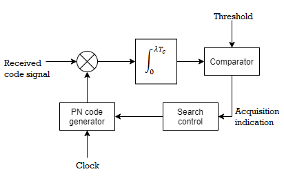
Fig 15 Direct Sequence spread spectrum systems – Serial Search Acquisition
The locally generated PN signal is correlated with the incoming PN signal. At fixed search intervals of N Tc (search dwell time), the output signal is compared to a preset threshold. If the output is below the threshold, the locally generated code signal is advanced in time by 1/2Tc seconds. The correlation process is repeated again. These operations are performed until a signal is detected or the threshold is exceeded. Then the PN code is assumed to have been acquired. Thus, if initially the misalignment between the two codes was n chips, the total time taken for acquisition is given by Tacq = 2nNTc seconds
B) FH spread spectrum systems
Figure below shows the serial search scheme for frequency hopping spread spectrum systems. Here the non-coherent matched filter consists of a mixer followed by a bandpass filter (BPF) and a square law envelope detector. The PN code generator controls the frequency hopper. Acquisition is accomplished when the local hopping is aligned with that of the received signal. Let fi be the frequency of the frequency synthesizer at the transmitter. Suppose fj be the frequency of the signal produced by the frequency synthesizer in the acquisition circuit of the receiver. If fi ≠ fj, then only a small voltage less than the threshold will be produced at the output of BPF. At a later instant of time during searching, if fi = fj, then a large voltage exceeding the threshold will be produced at the output of BPF. This indicates the alignment of local hopping with that of the received signal.
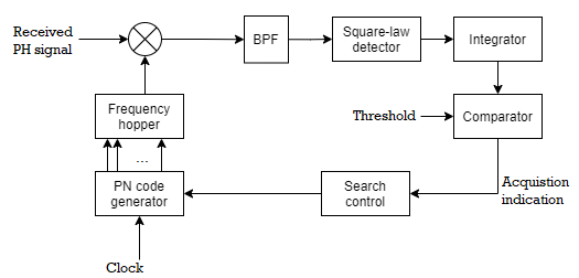
Fig 16 Frequency hopping serial search acquisition
2. Parallel search acquisition
The parallel search acquisition scheme introduces some degree of parallelism by having two or more correlators operating in parallel. They will search over nonoverlapping time slots. In this scheme, the search time is reduced at the expense of a more complex and costly implementation.
3. Sequential search acquisition
In this scheme, the dwell time at each delay in the search process is made variable by employing a correlator with a variable integration period whose (biased) output is compared with two thresholds. Hence the sequential search method results in a more efficient search in the sense that the average search time is minimised.
Tracking
Once the signal is acquired, the initial search process is stopped and fine synchronization and tracking begins. The tracking maintains the PN Code generator at the receiver in synchronism with the incoming signal. Tracking includes both fine chip synchronization and, for coherent demodulation, carrier phase tracking.
A) DS Spread spectrum system:
The commonly used tracking loop for a Direct sequence spectrum signal is the Delay-locked loop (DLL) as shown in the Figure
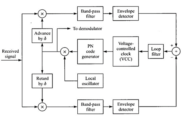
Fig 17 Delay-Locked Loop (DLL) for PN code tracking
The received DS spread spectrum signal is applied simultaneously to two multipliers. One of the multipliers is fed with PN code delayed by , a fraction of the chip interval. The other multiplier is fed with the same PN code advanced by . The output from each multiplier is fed to a BPF centred on f0. The output of each BPF is envelope detected and then subtracted. This difference signal is applied to the loop filter that drives the voltage controlled oscillator.
The VCO serves as the clock for the PN Code generator. If the synchronization is not exact, the filtered output from one correlator will exceed the other. Hence the VCO will be appropriately advanced or delayed. At the equilibrium point, the two filtered correlator outputs will be equally displaced from the peak value. Then the PN code generator output will be exactly synchronized to the received signal that is fed to the demodulator.
B) FH Spread spectrum system:
A typical tracking technique for FH spread spectrum signals is illustrated in Figure below. Although initial acquisition has been achieved, there is a small timing error between the received signal and the receiver clock. The BPF is tuned to a single intermediate frequency and its bandwidth is of the order of 1/𝑇𝑐, where Tc is the chip interval. Its output is envelope detected and then multiplied by the clock signal to produce a three-level signal. This drives the loop filter.
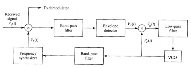
Fig 18 Tracking loop for FH signals
Suppose that the chip transitions from the locally generated sinusoidal waveform do not occur at the same time as the transitions in the incoming signal. Then the output of the loop filter will be either positive or negative, depending on whether the VCO is lagging or advanced relative to the timing of the input signal. This error signal from the loop filter will provide the control signal for adjusting the VCO timing signal so as to drive the frequency synthesizer output to proper synchronism with the received signal.
Short Answer Type Questions
Q1) What is spread spectrum communication?
A1) A system is defined to be a spread spectrum communication system if it fulfills the following requirements.
1. The signal occupies a bandwidth much in excess of the minimum bandwidth necessary to send the information.
2. Spreading is accomplished by means of a spreading signal, often called a code signal, which is independent of the data.
3. At the receiver, despreading (recovering the original data) is done by the correlation of the received spread signal with a synchronized replica of the spreading signal used to spread the information.
Q2) How a pseudo noise (PN) sequence can be generated?
A2) The class of sequences used in spread spectrum communications is usually periodic in that a sequence of 1’s and 0’s repeats itself exactly with a known period. The maximum length sequence, a type of cyclic code represents a commonly used periodic PN sequence. The maximum length sequences or PN sequences can be generated easily using shift register circuits with feedback from one or more stages. The length of the PN sequence is N = 2m–1, where m is the number of shift register stages.
Q3) Define Direct Sequence Spread Spectrum (DS-SS) system. What are the advantages and disadvantages of Direct Sequence Spread Spectrum (DS-SS) system?
A3) In the Direct sequence spread spectrum (DS-SS) systems, the use of a PN sequence to modulate a phase shift keyed signal achieves instantaneous spreading of the transmission bandwidth.
Advantages
1. This system combats the intentional interference (jamming) most effectively.
2. It has a very high degree of discrimination against the multipath signals. Therefore, the interference caused by the multipath reception is minimized successfully.
3. The performance of DS-SS system in the presence of noise is superior to other systems.
Disadvantages
1. The PN code generator output must have a high rate. The length of such a sequence needs to be long enough to make the sequence truly random.
2. With the serial search system, the acquisition time is too large. This makes the DS-SS system be slow.
Q4) List the commercial applications of spread spectrum techniques?
A4) Spread spectrum signals are used for
1) Combating or suppressing the detrimental effects of interference due to jamming (Intentional interference). It can be used in military applications also.
2) Accommodating multiple users to transmit messages simultaneously over the same channel bandwidth. This type of digital communication in which each user (transmitter-receiver pair) has a distinct PN code for transmitting over a common channel bandwidth is called as Code Division Multiple Access (CDMA) or Spread Spectrum Multiple Access (SSMA). This technique is popularly used in digital cellular communications.
3) Reducing the unintentional interference arising from other users of the channel.
4) Suppressing self-interference due to multipath propagation.
5) Hiding a signal by transmitting it at low power and, thus, making it difficult for an unintended listener to detect in the presence of background noise. It is also called a Low Probability of Intercept (LPI) signal. 6) Achieving message privacy in the presence of other listeners.
7) Obtaining accurate range (time delay) and range rate (velocity) measurements in radar and navigation.
Q5) Define synchronization. State and define the synchronization steps?
A5) The process in which the locally generated carrier at the receiver must be in frequency and phase synchronism with the carrier at the transmitter is called synchronization. In spread spectrum communication systems, there should be perfect alignment between the transmitted and received PN codes, for satisfactory operation.
The process of synchronizing the locally generated spreading signal with the received spread spectrum signal is usually done in two steps. They are
1) Acquisition: The first step called acquisition consists in bringing the two spreading signals into coarse alignment with one another.
2) Tracking: Once the received spread spectrum signal has been acquired, the second step, called tracking, takes over for fine alignment.
Case Study
Decision-Directed Channel Estimation for Multi-User OFDM
In a multi-user OFDM scenario the signal received by each antenna is constituted by the superposition of the signal contributions associated with the different users or transmit antennas. Note that in terms of the multiple-input multiple-output (MIMO) structure of the channel the multi-user single transmit antenna scenario is equivalent, for example, to a single-user space-time coded (STC) scenario using multiple transmit antennas. For the latter a Least-Squares (LS) error channel estimator was proposed by Li et al, which aims at recovering the different transmit antennas’ channel transfer functions on the basis of the output signal of a specific reception antenna element and by also capitalising on the remodulated received symbols associated with the different users. The performance of this estimator was found to be limited in terms of the mean-square estimation error in scenarios, where the product of the number of transmit antennas and the number of CIR taps to be estimated per transmit antenna approaches the total number of subcarriers hosted by an OFDM symbol. As a design alternative, in a DDCE was proposed by Jeon et al. For a space-time coded OFDM scenario of two transmit antennas and two receive antennas.
Specifically, the channel transfer function1 associated with each transmit-receive antenna pair was estimated on the basis of the output signal of the specific receive antenna upon subtracting the interfering signal contributions associated with the remaining transmit antennas. These interference contributions were estimated by capitalising on the knowledge of the channel transfer functions of all interfering transmit antennas predicted during the (n − 1)-th OFDM symbol period for the n-th OFDM symbol, also invoking the corresponding remodulated symbols associated with the n-th OFDM symbol. To elaborate further, the difference between the subtraction-based channel transfer function estimator and the LS estimator proposed by Li et al. In is that in the former the channel transfer functions predicted during the previous, i.e., the (n − 1)-th OFDM symbol period for the current, i.e., the n-th OFDM symbol are employed for both symbol detection as well as for obtaining an updated channel estimate for employment during the (n + 1)-th OFDM symbol period. In the approach advocated in the subtraction of the different transmit antennas’ interfering signals is performed in the frequency domain.
By contrast, in a similar technique was proposed by Li with the aim of simplifying the DDCE approach of, which operates in the time domain. A prerequisite for the operation of this parallel interference cancellation (PIC)-assisted DDCE is the availability of a reliable estimate of the various channel transfer functions for the current OFDM symbol, which are employed in the cancellation process in order to obtain updated channel transfer function estimates for the demodulation of the next OFDM symbol. In order to compensate for the channel’s variation as a function of the OFDM symbol index, linear prediction techniques can be employed, as it was also proposed for example. However, due to the estimator’s recursive structure, determining the optimum predictor coefficients is not as straightforward as for the transversal FIR filter-assisted predictor.
References:
1. Bernard Sklar, Prabitra Kumar Ray, “Digital Communications Fundamentals and Applications”, Pearson Education, 2nd Edition
2. Wayne Tomasi, “Electronic Communications System”, Pearson Education, 5th Edition
3. A.B Carlson, P B Crully, J C Rutledge, “Communication Systems”, Tata McGraw Hill Publication, 5th Edition
4. Simon Haykin, “Communication Systems”, John Wiley & Sons, 4th Edition
5. Simon Haykin, “Digital Communication Systems”, John Wiley & Sons, 4th Edition.