Unit-5
Potentiometer
A Potentiometer is an instrument designed to measure an unknown voltage by comparing with the known voltage. The known voltage may be supllied by a standard cell or other known voltage -reference source. Measurements using comparsion methods are capacble of high degree of accuracy because the result obtained does not depend on the actual deflection of pointer. Another advantage of potentiometers is that since potentiometer make use of balance or null condition no current flows and hence no power is consumed in the circuit containing the unknown emf when the instrument is balanced. Potentiometers are extensively used for calibration of voltmeterrs and ammeters.
5.1.1 Standardization
|
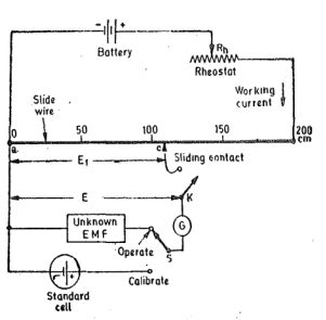
Figure 1. Basic slide wire Potentiometer
The procedure for standardisation of the potentiometer is as shown in figure. The slide wire has total length of 200cm and resistance of 200Ω. The emf of the standard cell is 1.0816 V . Switch ‘S’ is thrown to ‘calibrate’ position and the sliding contact is placed at 101.86cm mark on the slide wire scale. The rheostat R is now adjusted so as to vary the working current. This adjustment is carried on till the galvanomter shows no deflection when key ‘K’ is pressed. Under these conditions the voltage drop along the 101.86cm portion of slide wire is equal to stanadard cell voltage of 101.86V . Since 101.86cm portion of slide wire has a resistance of 101.86Ω the working current in fact has been adjusted to value :
1.0816/101.86 x1000 = 10mA
The voltage at any point along the slide wire is proportional to the length of slide wire. This voltage is obtined by converting the calibrated length into corresponding voltage simply by placing the decimal point in the proper position eg 153.6 cm = 1.536 V . If the potentiometer has been calibrated once its working current is never changed.
5.1.2 Application
In addition to measurement of voltage the potentiometer is the usual basis for calibration of all voltmeters, ammeters and wattmeters. The potentiometer may also be used for measurement of current, power and resistance. Since the potentiometer is a dc device the instruments to be calibrated must be d.c or electrodynamometer types.
Key Takeaways:
The potentiometer is a simple device used to measure the electrical potentials or compare the e.m.f of a cell.
5.2.1 Crompton Potentiometers
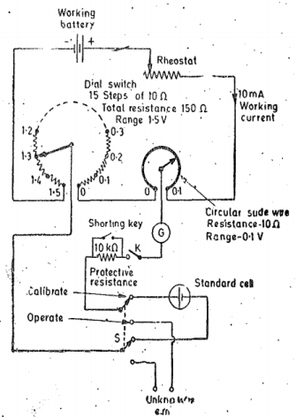
The slide wire type potentiometer is not a practical form of construction. The long slide wire is awkard and even for the length shown cannot be read to a very great degree of precision. Modern laboratory type potentiometers use calibrated dial resistors and small circular wire of one or more turns therby reducing the size of the instrument . The circuit is shown in the figure. There is one dial switch with fifteen steps each having precision resistor . There is also single turn circular slide wire . For the case shown the resistance of slide wire 10 Ω each. Thus dial has total resistance of 150Ω and in addiiton the slide wire has a resistance of 10Ω. The working current of the potentiometer is 10mA and therefore each step of dial switch corresponds to 0.1V. The slide aire is provided with 200 scale divisions and since the total resistance of slide wire corresponds to a voltage drop of 0.1V each division of slide wire corresponds to 0.1/200 = 0.0005V. This potentiometer is provided with double throw switch which allows the connection of either the standar cell or unknown emf to be applied to the working circuit. A key and protective resistance is used in the galvanometer circuit. In order to operate the galvanomter at its maximum sensitivity provision is made to short the protective resistane when near the balance conditions.
|
Figure 2. Crompton’s Potentiometer
5.2.2 Vernier Potentiometers
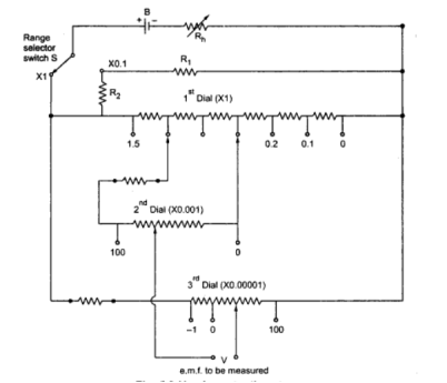
The main difference in simple and vernier potentiometer is that it uses three measuring dials. The slide wire is not used in this type of potentiometer. The main dial that is the first dial measures upto 15V range in steps of 0.1 volts. The second dial reads upto 0.1V in steps of 0.001 volts on the range. It consists of 102 studs. The third dial again with 102 studs measures from 0.00001 to 0.001 volts on range. This third dial provides true zero and negative setting.
The function of range selector switch S has range resistance R1 and R2. The resistances of the second dial shunt two of the coils of the main dial. The moving arm of the second dial carries two contacts which are placed two studs away from each other. The vernier potentiometer reads voltages of 10μV on X1 range while 1μV on X0.1 range. To have voltage reading of 0.1μV one more range X0.01 may be provided.
|
Figure 3. Vernier Potentiometer
Sometimes thermal sheilds are alo used to enhane process of reduction of potentials.
During the measurement of low resistance using Potentiometer the following readings were obtained
Voltage drop across the low resistance under test =0.4221V
Voltage drop across a 0.1 Ω standard resistance = 1.0235 V
Calculate the value of unknown resistance current and power lost in it.
Solution:
Resistance of the unknown resistor R = VR/VS = 0.4221/1.0235 x 0.1 = 0.041218Ω.
Current through the resistor = VB/S = 1.0235/0.1 = 10.235 A
Power loss in unknown resistance = I 2 R = (10.235) 2 x 0.041218 = 4.13 W
Key Takeaways:
A DC potentiometer is a potentiometer in which the supply is a battery and the balance is under direct current conditions.
5.3.1 Coordinate Type
|
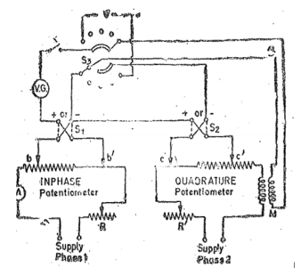
Figure 4. Gall type Potentiometer
The current in the in-phase potentiometer wire is first adjusted to its standard value by means of direct current supply and standard cell. The vibration galvanometer is replaced by galvanometer of the d’Arsonval type for this purpose. The dynamometer ammeter is of the torsion head type and the torsion head is turned to give zero deflection on direct current. This setting is left untouched during calibration with alternating current the slide wire current being adjusted to give zero deflection again. The vibration is then placed in circuit and direct current is replaced by alternating supplies.
The magnitude of the current in the quadrature potentimeter wire must be the same as that in the in-phase potentiometer. These two currents must be exactly in quadrature. Rheostat R is adjusted until the current in the in-phase potentiometer wire is the standard value. The selector S3 is then switched on to test position . The emf induced in the secondary winding of the mutual inductor M assuming M to be free from eddy currents effects will lag 90 o in phase behind the current in the primary winding. If I is the primary current then emf induced in the secondary is 2π x frequency x M xi, where M is value of mutual inductance.
5.3.2 Polar Type
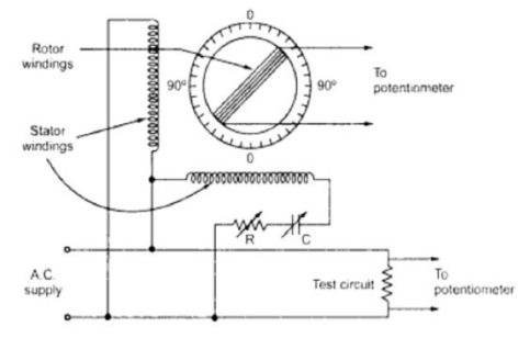
When current flows through stator winding a rotating field is produced inducing emf in the rotor.
The phase of rotor current can be changed through any angle relative to stator supply voltage by rotating rotor.
Thus the change in the phase of secondary emf is equal to the angle through which rotor is moved from its original position.
|
Figure5. Polar Type Potentimeter
Key Takeaways:
AC potentiometer measures both the magnitude and phase of unknown voltage by comparing it with a known reference.
References :
- Elements of Electronic Instrumentation and Measurement – by Carr
- Basic Electrical, Electronics and Measurement Engineering Paperback – 1 January 2019 by U.A Bakshi and A.P Godse.
- Electrical and Electronic Measurement and Instrument Paperback R.K Rajput
- Electrical & Electronic Measurements B. P. Patil, Pooja Mogre (Bisen)
- Electronic Measurements and Instrumentation by A.K. Sawhney
