Unit - 6
Power Electronics Applications
AC Voltage Controller using SCR
- AC voltage regulators have a constant voltage ac supply input and incorporate semiconductor switches which vary the rms voltage impressed across the ac load. These regulators fall into the category of naturally commutating converters since their thyristor switches are commutated by the alternating supply. This converter turn-off process is termed line commutation.
- The regulator output current, hence supply current, may be discontinuous or non-sinusoidal and therefore input power factor correction and harmonic reduction are usually necessary, particularly at low output voltage levels.
- Therefore, ac to ac converters are potentially more efficient but usually involve a larger number of switching devices and output is lost if the input supply is temporarily lost.
Single-phase ac regulator
AC voltage regulator is a type of thyristor power converter which is used to convert a fixed voltage, fixed frequency ac input supply to obtain a variable voltage ac output. The RMS value of the ac output voltage and the ac power flow to the load is controlled by varying (adjusting) the trigger angle ‘α’

The basic principle of on-off control technique is explained with reference to a single phase full wave ac voltage controller circuit shown below. The thyristor switches T1 and T2 are turned on by applying appropriate gate trigger pulses to connect the input ac supply to the load for ‘n’ number of input cycles during the time interval ON t .
The 3 thyristor switches T1 and T2 are turned off by blocking the gate trigger pulses for ‘m’ number of input cycles during the time interval OFF t . The ac controller ON time ON t usually consists of an integral number of input cycles.
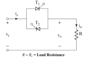
Figure 1. Single phase AC regulator

Figure 2. Waveforms
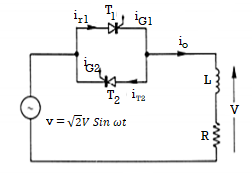
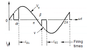
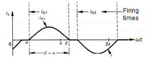
R-L load
(a)
(b)
Figure 3. AC regulator for R-L load
Concept of two stage AC voltage regulator
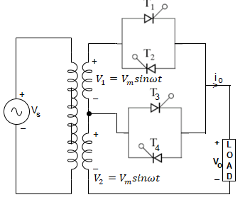
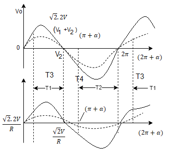
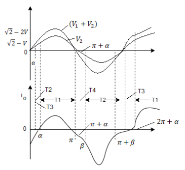
Figure 4. Two stage AC voltage regulator
The two stage sequence control of ac voltage regulators employs two stage in parallel as shown in figure a. The turns ratio from primary to each secondary is taken as unity . This means that for source voltage vs = Vm sinwt , v1=v2 = Vm sin wt and sum of two secondary voltage is 2Vm sin wt.
The load may be R or R-L . For both types loads for obtaining output voltage control from zero to rms value.
Resistance load:
The load current waveform is identical with output voltage waveform. When thyristor pair T3,T4 is in operation the output and voltage and current waveform are shown in figure.
When T3,T4 is in operation then out put voltage and current waveforms are shown in (b) . When both the pairs T1,T2.T3 and T4 are in operation then firing angle for T3,T4is zero and firing angle α for pair T1, T2 is varied from 180 to zero for obtaining output voltage from V to 2V
R-L load:
When pair T3,T4 in operation then the waveforms of output voltage and current waveform is shown in fig (b)and (c) for α > Ø and α ≤ Ø.
For obtaining output voltage from V to 2V firing angle for T3,T4 is zero for T1,T2 is varied from 180 to zero. For T1,T3 firing pulses vary for wt = 0 to π and during negative half cycle t2,t4 extend from wt = π to 2π
AC Voltage Controller using IGBT
The mains supply is an alternating current in the form of a sine wave. The common power supply to households is a single phase AC supply. The frequency and the amplitude of the AC wave vary from region to region with 50 Hz or 60 Hz being the common frequency and an amplitude of 110V or 240V.
The power rating of an electrical device or appliance will determine the power utilized by it to work properly. What if we desire to reduce the intensity of an electric bulb or run a motor at less speed? This can be achieved by limiting the power to the device i.e. supplying less power than the maximum rated power. This concept of restriction on the power supplied to a device is known as AC power control. AC power control allows us to efficiently use the available power for various applications.

Fig 5 Circuit Diagram
There are two types of AC power control: ON-OFF or pulse skipping modulation control and phase control. In on-off control, the load is connected to the AC supply for short interval of time and the AC supply is switched off for some interval.
A fast switching device like a thyristor is used to connect and disconnect the load to the AC power supply. In phase control method, the load is connected to the AC supply for a specific period of both the half cycles. A PWM technique based AC power control is designed here which is a type of on-off control. The circuit regulates the AC power supplied to any load like an electric bulb, motor, amplifiers etc.
The aim of this circuit is to control the AC power supplied to an electrical device like a light bulb with the help of pulse width modulated AC sine wave. The AC power supply (240V @ 50Hz) is given to a bridge rectifier (BR1). This is further rectified with the help of diode D1 and the filter circuit formed by the resistor R1 and capacitor C1. The output of this filtered signal is a DC signal, which is given to the optocoupler as DC voltage. A light bulb is connected in series with the bridge and the power supply.
An Arduino Uno board is used to generate the PWM wave. Four switches are used with the Arduino to select different duty cycles of PWM signal. The four switches associated with the Arduino provide duty cycles of 0%, 25%, 50% and 75%. When no switch is pressed, maximum power is delivered to the light bulb. The PWM signal from the microcontroller (Arduino) is given to the input of an Optocoupler (CNY65) with the transistor in the optocoupler connected to DC voltage from the rectifier for quick conduction.
A resistor (R5) is used in series with the optocoupler to protect the IR emitting diode in the optocoupler. Resistor R4 is used to reduce the switching spikes. The purpose of the optocoupler is to isolate the low voltage PWM signal from the large voltage and current in the transistor. The output of the optocoupler is the same PWM signal from the microcontroller (Arduino) and will act as the input signal applied to the gate of the transistor.
The transistor must be a high speed switching device which can handle large power. Hence, a power MOSFET or IGBT can be used. The important thing to remember when operating with MOSFET and PWM is that the MOSFET stays on How PWM can be used to control the AC power? The most effective way to control the AC power is to tune the frequency of the AC signal. Consider a situation where a switch is present between the electrical device like a bulb and the mains power supply.
If the switch is ON (or closed) for 2 seconds and OFF (or open) for 2 seconds, then the power consumption is reduced by 50%. If the switching action is so fast that it is not detected by the human eye, then the light bulb will appear a
s it is continuously glowing with half the luminance and consuming only 50% power. An IGBT or a MOSFET is used as a switch and the switching action of the transistor is controlled by a pulse.
The on (high) and off (low) period of the pulse will determine whether the transistor is switched on or off and consequently controlling the AC power and this is how a PWM signal is used in AC power control. The on and off periods of the PWM wave define a factor called Duty cycle and this is an important parameter in controlling the power. A 50% duty cycle PWM wave will provide only 50% of the maximum power and a 33% duty cycle PWM will deliver only 33% of the maximum power. An important thing to be considered when choosing the switching device is that it should have a fast switching action and also should be capable of handling large power
Key takeaway
The two stage sequence control of ac voltage regulators employs two stage in parallel. The turns ratio from primary to each secondary is taken as unity. This means that for source voltage vs = Vm sinwt , v1=v2 = Vm sin wt and sum of two secondary voltage is 2Vm sin wt.
The load may be R or R-L . For both types loads for obtaining output voltage control from zero to rms value.
Fan Regulator:
- The light dimmer circuit or fan regulator circuit is used to control the speed of the fan according to our necessity. The objective of the circuit is to vary the intensity of the fan speed by using a fixed source.
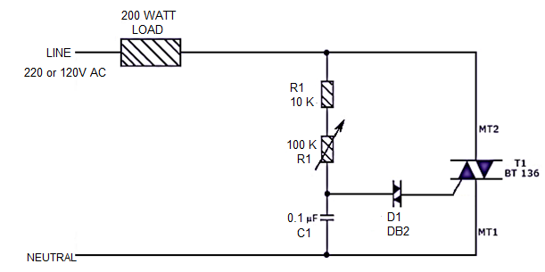
- The circuit diagram of fan regulator is as shown in the figure. The circuit is based on the principle of power control using a Triac. The circuit works by varying the firing angle of the Triac.
- Resistors R1, R2 and capacitor C2 are associated with this. The firing angle is varied by varying the value of any of these components. Here, R1 is selected as the variable element. By varying the value of R1 the firing angle of Triac changes.
- This directly varies the load power, since Triac drives load. The firing pulses are given to the gate of Triac T1 using Diac D1.
- An electronic ballast is a device, which controls the starting voltage and the operating currents of lighting devices.
- It does this through the principle of electrical gas discharge. It will convert power frequency to a very high frequency to initialize the gas discharge process in the fluorescent - lamp by controlling voltage across the lamp and current through the
Lamp.
- The Electronic ballast takes supply at 50 – 60 Hz. It first converts AC voltage into DC voltage. After that, filtration of this DC voltage is done by using capacitor configuration.
- The filtered DC voltage is fed to the high-frequency oscillation stage where oscillation is typically square wave and frequency range are from 20 kHz to 80 kHz.

- Hence, the output current is with very high frequency. A small amount of inductance is provided to be associated with a high rate of change of current on high frequency to generate high value.
- Usually more than 400 V is required to strike the gas discharge process in fluorescent tube light.
- When the switch is ON, the initial voltage across the lamp becomes 1000 V around due to high valued, hence gas discharge takes place instantaneously.
- Once the discharge process is started, the voltage across the lamp is decreased below 230V up to 125V and then this electronic ballast allows limited current to flow through this lamp.
- The control unit of the electronic ballast does this control of voltage and current.
- In running condition of fluorescent lamp, electronic ballast acts as a dimmer to limit current and voltage.

The basic components used in the Electronic Ballast are:
- EMI filter: Blocks any electromagnetic Interference
- Rectifier: Converts AC power to DC power
- PFC: It does Power Factor Correction
- Half-Bridge Resonant Output: Converts DC to square waved voltage with high frequency (20 kHz to 80 kHz).
- Control Circuit: Controls voltage and current across and through the lamp respectively.
Led driver changes the power supply to a specific voltage current to drive the LED voltage converter. In general, the input of the LED driver includes the high voltage power frequency AC (i.e., the city electricity), the low voltage DC, the high voltage DC, the low voltage and high-frequency AC (such as the output of the electronic transformer). The output of LED driver power is mostly a constant current source that can change voltage with the change of LED forward voltage drop. The core components of the LED power supply include switch controller, inductor, switch component (MOSFET), feedback resistor, input filter device, output filter and so on. According to the requirements of different occasions, there must be input over-voltage protection circuit, input under-voltage protection circuit, LED open circuit protection, over-current protection circuit and so on.
Types
LED Driver Constant Current
According to the driving mode, the common market-led lamp driver is divided into two kinds. One is constant current drive. The characteristic of a constant current drive is that the output current is constant. The output voltage is changed in one range. So we often see that the driving shell is marked out (output: DC**V - **V * * * mA+-5%) in the market. This means that the output voltage is in one of the output voltages. The range, the current is how many ma.
A. The output current of the constant current drive circuit is constant, but the output DC voltage varies in a certain range with the different sizes of the load. The load resistance is small, the output voltage is low, the greater the load resistance is, the higher the output voltage is.
B. Constant current circuit is not afraid of load short circuits, but it is strictly forbidden to load fully open.
C. The constant current drive circuit is ideal for driving LED, but relatively speaking, the price is higher.
D. Attention should be paid to the maximum withstand current and voltage used, which limits the number of LEDs used.
LED Driver Constant Voltage
And the other is the constant voltage drive. The constant voltage driving characteristic is that the output voltage is fixed, and the current is limited to the maximum value with the change of the lamps and lanterns. In this case, the shell usually indicates (output: DC**V **A) the voltage of the output fixed volt, and how many maximum output currents are available. The most common output voltages in the led market are 5V, 12V, 24V, and so on.
A. When the parameters in the voltage stabilizing circuit are determined, the output voltage is fixed, whereas the output current varies with the increase or decrease of the load.
B. The voltage stabilizing circuit is not afraid of load opening, but load short circuits are strictly forbidden.
C. A regulated drive circuit powers the LED. Each string requires a proper resistor to average the brightness of each string LED.
D. The rectified voltage changes will affect the brightness.
Single Phase separately excited DC motor drive:
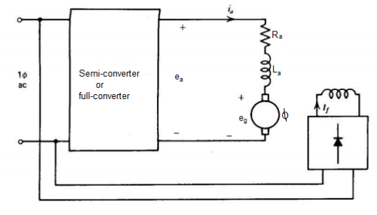
- The basic circuit for single phase separately excited dc motor drive is as shown in figure. Semi-converter or full converter controls the armature voltage and the field circuit is fed from the ac supply through the diode bridge.
- The motor current cannot reverse due to thyristors in the converter. If semi-converters are used then the average output voltage Ea is always positive.
- Therefore power flow (EaIa) is always positive from ac supply to dc load.
- In drive system semi-converters regeneration or reverse power flow from motor to ac supply is not possible. In semi-converters free-wheel takes place when the thyristor blocks.
- Single-phase full wave drives are used for low and medium-horse power applications as shown in figure. Such drive have poor speed regulation on open-loop firing angle control. However, the armature voltage or tachometer feedback good regulation can be achieved.
- The armature circuit of the dc motor is represented by its back voltage eg armature resistance Ra and armature inductance La as shown in figure.
Back voltage es = Ka n ----------------------------(1)
Average back voltage Eg = Ka n -----------------------------(2)
Developed torque t = Ka a --------------------------------(3)
Average developed torque T = Ka Ia-----------------------------------(4)
The armature circuit voltage equation is
Ea = Ra ia + La dia/dt + eg ------------------------------------------------------(5)
In terms of average values,
Ea = Ra Ia + Eg ------------------------------------------------(6)
The inductance La does not absorb any average voltage . From eq(2) and (6) the average speed is given by
N = Ea – Ra Ia / Ka -------------------------------------------------------------(7)
In single phase, converters the armature voltage ea and current t change with time. In phase controlled converters the armature current may not be continuous for most operating conditions it is discontinuous.
BDLC Motor Drive
- The self-controlled variable frequency drive employing a sinusoidal PMAC (Permanent Magnet Alternating Current) motor is called brushless DC motor drive.
- The advantages are they require no maintenance and have a long life. They also have low frequency, low inertia and friction, and low radio frequency interference and noise.
- It is used in record players, the tape drive for recorders, spindle drive in hard disks for computers, and low power drives in computers peripherals instruments and control systems. They also have applications in aerospace, in biomedical and in driving cooling fans, etc.
- The cross section of a three-phase two pole trapezoidal PMAC motor is shown in the figure below. This drive has a permanent magnet rotor with wide pole arc.
- The stator of the drive has three poles winding which is displaced by 120º and each phase winding spans 60º on each side.

The voltage induces in three phases are shown in the figure below. The reason for getting the trapezoidal waveform is that when the rotor revolving in a counter-clockwise direction, then up to 120º rotation from the position all the top conductor of phase A will linking the south pole and all the bottom of phase A will be linking the north pole.
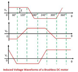
- The voltage induced in phase A will be the same during 120º rotations and beyond 120º some conductors in the top link north pole and others the south pole.
- Similarly, the voltage induces in the bottom conductors. The wave voltage induces in phase A linearly reverse in next 60º rotation. Similarly, the voltage induces in the phases B and C.
- The brushless DC motor drive uses voltage source inverter and trapezoidal PMAC motor shown in the figure below. The stator windings are star connected. The phase voltage waveform for a trapezoidal PMAC motor is shown in the figure below.
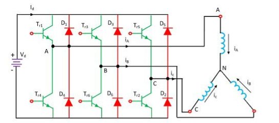
- The stator winding is fed with a current pulse, and each of the pulses had duration 120º and located in the region where induced voltage is constant and maximum.
- The polarity of the current pulse is same as that of the induced voltage. The air gap flux is constant and the voltage induced is proportional to the speed of the rotor.
Variable voltage and variable frequency three phase induction motor drive
Induction motors, particularly squirrel cage IM, have many advantages when compared to DC motors. They are,
- Ruggedness
- Lower maintenance requirements
- Better reliability
- Low cost,
- Less weight and volume
- Higher efficiency
- Induction motors are able to operate in dirty and explosive environments. Because of the above said advantages, induction motors are predominantly used in many industrial applications.
- Induction motors were used only for applications requiring constant speed. DC motors were used for variable speed applications as their speed control is cheap and efficient when compared to induction motors.
- After the advent of power electronic converters, it was able to design variable speed drives for induction motors.
VOLTAGE / FREQUENCY CONTROL (OR) VOLTS / HERTZ CONTROL
Varying the voltage alone or frequency alone has some disadvantages with regards to the operation of induction motor. The maximum torque in an induction motor is given by
Tmax = K(V/f) 2 /{ [R/f ± 4  2 ( L2 + L’r) 2 ]} ½ -------------------------(1)
Here K is a constant and Ls & Lr’ are the stator and stator referred rotor inductances. At high frequencies, the value of (Rs / f) will be very much less than 2π (Ls+ Lr’). So (Rs / f) can be neglected and hence the torque equation becomes,

 -----------------------(2)
From equation 2, it is clear that if the ratio (V / f) is kept constant, the motor can produce a constant maximum torque, Tmax. That is constant torque operation.

V – f relationship Speed-Torque characteristics
(a) (b)
From the graph of it is clear that (V/f) ratio is increased at low frequency to keep maximum torque constant.
- (V/f) ratio is kept constant at high frequencies up to base frequency
- V is kept constant and frequency is varied above base frequency.
- From Fig. b, it is clear that the maximum torque is same at all different speeds.
This volts / Hertz control offers speed control from standstill up to rated speed of IM.
- This (V/f) control is achieved by using VSI and CSI fed induction motor drives.
- If a six step inverter is used, the frequency alone can be varied at the inverter output and the output voltage is controlled by varying the input dc voltage.
- If a PWM inverter is used, both voltage and frequency can be varied inside the inverter itself by changing the turn on and off periods of the devices.
Offline UPS
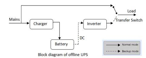
Offline UPS supply grid power to electrical and electronic devices during normal power supply. It switches to battery power only during power failures and other power problems.
As the grid power is bypassed to the load during normal power supply, it is known as Offline UPS. As the UPS is used only during power problems, it is also known as Standby UPS.
Apart from bypassing power to the load, Offline UPS also charges the connected batteries during normal power supply. The bypassing of power results in exposing the load to electrical noises and surges.
Therefore, they are not recommended for very sensitive and critical electronic devices. During power failures and other power problems, they switch from grid power to battery power fast enough to prevent computers from rebooting. The switch over time is usually between 2 to 20ms.
Online UPS
Online UPS supply power to electrical and electronic devices from batteries all the time. The UPS first converts grid power to charge the batteries and then discharges the batteries to power the load.
As the battery power is supplied to the load at all times, it is known as Online UPS. The grid power is converted from (Alternating Current) AC to DC (Direct Current) to charge the battery and the battery power is converted from DC to AC to power the load.
Therefore, online UPS is also known as Double Conversion UPS.As Online UPS always provides power from the battery, the load always get clean power regardless of any power problems.
Therefore, Online UPS is recommended for sensitive and critical electronic devices. Online UPS provide a layer of insulation or electric firewall. Any change in the input voltage or frequency does not affect the output voltage and frequency. Therefore, the load is shielded from all power problems.

Standards ensure interoperability and compatibility of any EVSE with all EVs. The Bureau of Indian Standards (BIS), the national standards body of India, is responsible for formulating EV charging standards for the country. BIS is a member of the International Electrotechnical Commission (IEC), which is the global body that is developing reference standards to ensure interoperability and minimize trade barriers for electric vehicles and their components. While Indian standards for EV charging are compliant with global standards, local climate considerations and the difference in vehicle types available in the country necessitate modifications that are specifically applicable to India.
INDIAN STANDARDS FOR AC CHARGING
IS 17017 is the key EV charging standard in India comprising three parts and six sections. IS-17017- Part-1 provides the basic features of all EV charging systems. An AC EVSE must adhere to this standard, and specific AC connector standards in the IS-17017-Part-2. Both AC and DC EVSE need to conform to the technical standards IS-17017-Parts 21 & 22. Additional Indian standards for AC EVSEs have been approved for light EVs and e-cars (in the form of low-cost charging points), for use in parking areas.
INDIAN STANDARDS FOR DC CHARGING
IS-17017-Part-23 describes the requirements for DC charging stations, with power output of 50kW to 200kW. Beyond this, high power charging standards are required to cater to buses and other heavy vehicles. Recently, the BIS has finalized the IS-17017-Part-25, which is specifically for providing low DC power of less than 7kW for light EVs. Due to the requirement of digital communications between the DC EVSE and the EV, data communication standards are specified in IS-17017-Part 24. When the Combined Charging System (CCS) standard is deployed, which can provide both AC and DC charging, communications will be as per the IS-15118 series.
INDIAN STANDARDS FOR BATTERY SWAPPING
Separate projects have been initiated for battery swapping standards for LEVs and buses. They will be two series of standards documents, covering the form factor of the battery pack, inter-operable connection systems, communication between the battery management system (BMS) and the EV and charging station, and network management. Any EV may utilize a battery pack conforming to these standards. The removable battery packs can be charged using AC or DC charging systems. The BIS is yet to develop Indian standards for EV roaming and grid-related management functions.
Performance parameters of batteries in battery operated power systems
Cell and battery voltages All electric cells have nominal voltages which gives the approximate voltage when the cell is delivering electrical power. The cells can be connected in series to give the overall voltage required. The ‘internal resistance’ and the equivalent circuit of a battery is shown. The battery is represented as having a fixed voltage E, but the voltage at the terminals is a different voltage V, because of the voltage across the internal resistance R. Assuming that a current I is flowing out of the battery, then by basic circuit theory we can say that:

V =E -IR
Charge (or Ahr) capacity
The electric charge that a battery can supply is clearly a most crucial parameter. The SI unit for this is the Coulomb, the charge when one Amp flows for one second. The capacity of a battery might be, say, 10Amphours. This means it can provide 1Amp for 10 hours.
Energy stored
The energy stored in a battery depends on its voltage, and the charge stored. The SI unit is the Joule, but this is an inconveniently small unit, and so we use the Whr instead.
Energy in Whr= V X Ahr
Specific energy
Specific energy is the amount of electrical energy stored for every kilogram of battery mass. It has units of Wh.kg−1
Energy density
Energy density is the amount of electrical energy stored per cubic metre of battery volume. It normally has units of Wh.m−3
Specific power
Specific power is the amount of power obtained per kilogram of battery. It is a highly variable and rather anomalous quantity, since the power given out by the battery depends far more upon the load connected to it than the battery itself.
Ahr (or charge) efficiency
In an ideal world a battery would return the entire charge put into it, in which case the amp hour efficiency is 100%. However, no battery does; its charging efficiency is less than 100%. The precise value will vary with different types of battery, temperature and rate of charge. It will also vary with the state of charge.
Energy efficiency
This is another very important parameter and it is defined as the ratio of electrical energy supplied by a battery to the amount of electrical energy required to return it to the state before discharge.
Self-discharge rates
Most batteries discharge when left unused, and this is known as self-discharge. This is important as it means some batteries cannot be left for long periods without recharging. The rate varies with battery type, and with other factors such as temperature; higher temperatures greatly increase self-discharge.
Electric vehicle supply equipment (EVSE) is the basic unit of EV charging infrastructure. The EVSE accesses power from the local electricity supply and utilizes a control system and wired connection to safely charge EVs. An EVSE control system enables various functions such as user authentication, authorization for charging, information recording and exchange for network management, and data privacy and security. It is recommended to use EVSEs with at least basic control and management functions, for all charging purposes.
Conductive charging, or plug-in (wired) charging, is the mainstream charging technology in use. Requirements of EVSE for conductive charging depend on factors such as vehicle type, battery capacity, charging methods, and power ratings
In India, transport electrification over the next decade is expected to be driven by light electric vehicles (LEVs), comprising two-wheelers (scooters, motorcycles) and three-wheelers (passenger and cargo). Apart from these, cars and light commercial vehicles (LCVs) are the other key vehicle segments being electrified.
EV charging requirements depend on the specifications of EV batteries, as power must be supplied to the battery at the right voltage and current levels to permit charging. Typical capacity and voltage of EV batteries vary among the different EV segments, as shown in Table
E-2Ws and e-3Ws are powered by low-voltage batteries. The first generation of e-cars is also powered by low voltage batteries. However, these are likely to be phased out in the future, even if they continue in specific use cases such as taxis. The second generation of e-cars, as seen in the upcoming e-car models, is powered by high-voltage batteries. Electric LCVs will comprise of both low-voltage and high-voltage vehicles, depending on their load-carrying capacity.
Vehicle Segment | Battery Capacity | Battery Voltage |
E-2W | 1.2-3.3kWh | 48-72V |
E-3W | 3.6-8kWh | 48-60V |
E-cars (1st generation) | 21kWh | 72V |
E-cars (2nd generation) | 30-80kWh | 350-500V |
CHARGING METHODS AND POWER RATINGS
EV charging involves supply of direct current (DC) to the battery pack. As electricity distribution systems supply alternate current (AC) power, a converter is required to provide DC power to the battery. Conductive charging can be AC or DC. In the case of an AC EVSE, the AC power is delivered to the onboard charger of the EV, which converts it to DC. A DC EVSE converts the power externally and supplies DC power directly to the battery, bypassing the onboard charger.
AC and DC charging are further classified into four charging modes, with Modes 1-3 pertaining to AC charging and Mode 4 pertaining to DC charging. Modes 1 and 2 are applicable for connecting an EV to a standard socket outlet, utilizing a cable and plug. Mode 1, also known as dumb charging, permits no communication between the EV and EVSE and its use is not recommended. The portable cable used in Mode 2 has an inbuilt protection and control capability and is typically used for home charging. Modes 3 and 4, which provide a separate charger device to supply power to the EV, have improved control systems and are used for commercial or public charging
POWER RATINGS
EVSEs have different power ratings or levels based on charging requirements, which in turn determine the input power requirements for charging infrastructure. Table 2 categorizes EV charging by power level, with normal power charging going up to 22kW and highpower charging going up to 200kW. While EVSEs with power ratings up to 500kW are globally available, they are largely applicable for heavy vehicles like buses and trucks. Normal power AC charging is adequate for e-2Ws, e-3Ws and e-cars. Normal power DC charging is unique to India, due to the prevalence of LEVs, and the use of low-voltage batteries in e-cars. Single-phase AC chargers, with a maximum power rating of 7kW, are adequate for LEVs and cars with single phase on-board chargers. Three-phase AC chargers, with a power rating up to 22kW, are required for e-cars with larger onboard chargers. Input power supply for normal power charging can be provided from the standard electricity distribution network. For high-voltage e-cars with battery capacities between 30-80kWh, high-power DC charging of 50kW is used. The power level of DC chargers in the market ranges between 25kW and 60kW. However, higher powered DC chargers will be available in the near future. While high-power DC charging takes less time for e-cars, it requires higher electricity supply with additional infrastructure. Normal power charging points are therefore adequate for most charging requirements, including slow or overnight charging of e-cars.
BATTERY SWAPPING
An alternative battery recharging method that is receiving global attention is battery swapping, in which a depleted EV battery is removed from the vehicle and replaced with a fully charged one. The technology is being tried out for various EV segments, including e-2Ws, e-3Ws, e-cars and even e-buses.
TYPES OF BATTERY SWAPPING
Manual: The battery swapping station is a standalone device, in which batteries are placed and removed manually from the individual slots, usually by hand. Manual swapping stations are modular and occupy a minimal amount of space. These are used for 2W and 3W battery applications, as the battery pack sizes are smaller and the weight can be handled by one or two persons.
Autonomous: A robotic arm is used in these types of swapping stations with the battery swapping process being semi/fully automated. Robotic swapping is used for 4W and e-bus applications as battery packs are larger and heavier, and require mechanical assistance. These swapping stations are also more expensive and have a higher land requirement.
At present, battery swapping is considered a feasible solution for commercial EV fleets, especially in the e-2W and e-3W segments. The Ministry of Road Transport and Highways (MoRTH) has allowed the sale and registration of EVs without batteries, which provides a huge boost to battery swapping solutions. Further, industry stakeholders are making large investments in developing the battery swapping ecosystem. This indicates that battery swapping will emerge as a distinct part of EV charging networks in India in the coming years.
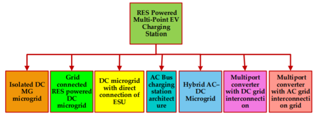
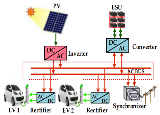
A microgrid-based charging station architecture combines energy sources and ESU localization of distributed loads, offering the capability of operating in a connected grid or in islanding mode. A charging station with renewable energy sources provides an option for charging of the EV without any power conversion losses. There are different types of RES connected to the DC bus, like PV, wind, super capacitor, and fuel cell. Some of the problems in microgrids include steady-state and transient voltage and frequency control. The different types of charging station architectures are shown in Figure 8. In addition, there are problems associated with protection and short circuit, and power quality during islanding and fault conditions of the system. The photovoltaic system is the main source of renewable energy in an RES-powered DC bus system, with a different arrangement to supply power to the local load and EV. This section discusses the different architecture of microgrids used for EV charging. Based on RES and a load connection charging station, a different topology is framed, one that requires a different energy management control strategy.
Isolated DC Microgrid for EV Charging
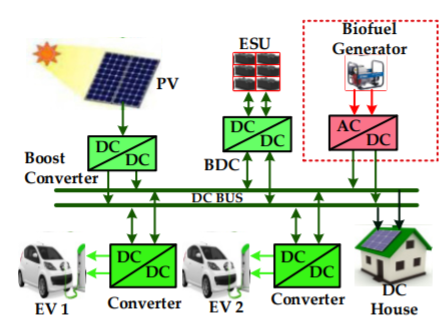
An isolated DC microgrid is powered by renewable/non-renewable energy sources such as PV or biofuel generators through dedicated converters. In isolated microgrids, a common DC bus is used for efficient integration storage and renewable energy sources. Diesel generators are frequently used to generate electricity, posing environmental and logistical challenges. Diesel power plants emit a lot of greenhouse gases. Furthermore, diesel must be transported to remote locations, posing concerns, such as leaks on islands. Renewable energy sources (RESs) have thus been implemented in many parts of the world to address such challenges. The generation of renewable energy sources, however, has a lot of changes and uncertainties, which might lead to problems in stability. DC microgrid integration with energy sources is not required for frequency and phase synchronization, like the AC grid system. Therefore, a DC microgrid system can be used when a DC load is connected to the grid. The only problem is that the DC bus voltage needs to be stabilized. This type of microgrid architecture can supply load power based on the power available at the generation side. In an isolated DC microgrid system, it is easy to optimize power flows at the DC bus with minimum cost of power control signal and transmission; a structure of this microgrid is shown in Figure. The isolated microgrid-based charging suggests that investing in new PV generation and implementing EV charging techniques for a new fleet will result in a lower microgrid net present cost, particularly if EV penetration is high.
Isolated DC Microgrid Control Strategy
The control and management of microgrids are performed based on meteorological conditions and load consumption using short-term forecasting data. Optimization based control is mostly followed in this type of microgrid. Optimization is implemented based on the predicted output by satisfying the constraints. The DC bus voltage-based control strategy is used for load consumption and generation, and power balancing is performed by controlling energy storage and local biofuel generators. The power control required for a DC isolated microgrid is taken as the reference and denoted as p*. Power balancing is done by regulating the DC bus voltage with a proportional-integral controller.

Where Ppv is the power supplied by the PV, PL is the power required by the load, v* is the DC bus reference voltage, CP and CI are proportional and integral gain of the PI controller, respectively. Then, p* defines a distributed storage and biofuel generator optimized value.
Grid-Connected, RES-Powered DC MG for EV Charging
The grid-connected topology shares a common DC bus between all the sources and load; it also allows the PV and the battery storage to work in parallel. The EVs charged from the PV or ESU mostly depend on RES; the decision depends on power management. The PV is connected to the DC bus using MPPT and ESU is connected using a bidirectional converter. The main drawback of this architecture is DC-to-AC conversion for grid integration. Another characteristic is the ability of the energy storage to feed the grid or load of the households. This architecture can operate in various modes based on the power available at the charging station. This architecture can be used for charging electric vehicle batteries using DC supply, as shown in Fig.
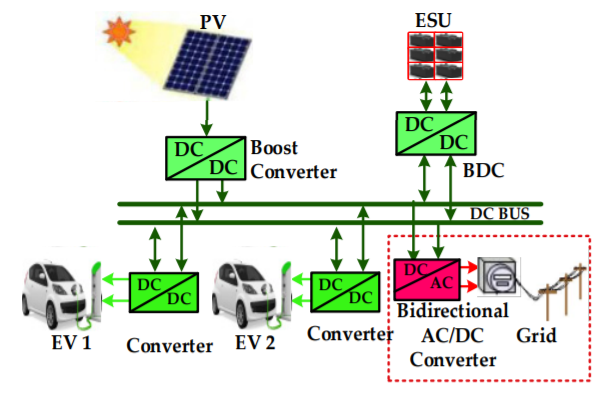
The power prediction model developed depends on an individual customer’s power requirements. During huge power demand, the power prediction model acts quickly and efficiently to respond to the charging station. The power required for charging the ith EV is based on the SOC of the vehicle, plugged time, and charging mode.

Where SEVi,req is the required SOC applied by an ith customer using the human machine interface i, PTEVi is the plugged time set to adapt the matched charging mode, CEVi is the battery capacity of the ith EV. During the time of multiple EV connections, power demand is calculated from the following equatio

When a particular EV (ith EV) is connected to the charging point, the energy management system will measure from the human machine interface of the ith and compensate for the lack of power for EV charging. The real-time monitoring of the ESU with respect to PTEVi is:

RES-Powered DC Microgrid with Direct Connection of ESU
The RES of PV connected using a unidirectional converter and ESU using electrochemical battery stacks are directly connected to the DC bus. A PV converter controlled through maximum power point tracker (MPPT) provides regulated supply to the utility grid. The numbers of series battery cells are determined depending on the DC bus voltage. If the ESU is directly connected to the DC bus, it is required to regulate the charging voltage. The direct connection of ESU will cause a circulating current problem that leads to uneven loading of those converters. To control the power flow, communication between the converter and inverter is required using a coordinated control strategy. The RES-powered DC microgrid with a direct connection of ESU is shown in Figure
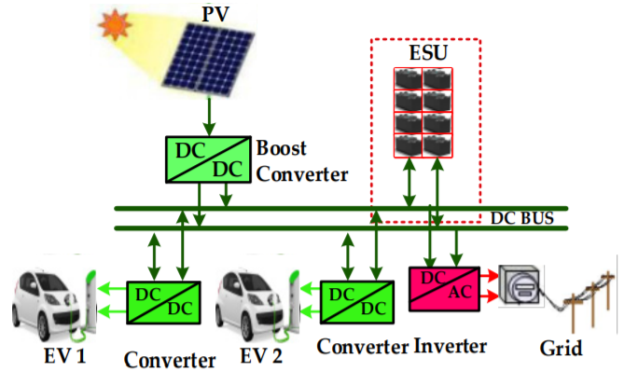
The microgrid with direct connections of ESU is the most common type of DC MG, frequently deployed in practical industrial applications. Based on the DC bus, the ESU, used as electrochemical battery stacks, is directly connected. However, the architecture creates dynamic stability, such as uncontrollable DC bus voltage, SOC, and current limitation [86]. It is most suitable for singular DC bus systems, however, creating practical problems like unregulated battery charging and inherent imperfections in bus voltage measurement.
AC Bus Coupled Charging Station Architecture
In AC-coupled microgrid architecture, all the loads are connected to the common AC bus, as shown in Figure. In this, the ESU is connected to the AC bus through the AC-to-DC bidirectional converter. This type of architecture gives an option for sizing of all the parts independently. The connection to the grid and local load might provide more flexibility to the system in terms of charge and discharge of the battery and peak time management. The AC bus-coupled architecture is preferred for home-based charging due to its well-defined standards. In addition, AC technology and its products are already available in the market. However, considering renewable energy sources, solar integration DC bus-based systems are more efficient due to fewer amounts of conversion loss. The AC grid-based charging station requires power compensation to measure active power at the point of common coupling. However, considering renewable energy sources, solar integration DC bus-based systems are more efficient due to fewer amounts of conversion loss. The AC grid-based charging station requires power compensation to measure active power at the point of common coupling.
Multiport Converter with DC Grid Interconnection
A multiport converter for the charging operation mode is used for different sources and loads. Based on the requirements, connecting points are designed as bidirectional or unidirectional converters. In addition, when there is more PV power generation, the excess power is fed back to the utility grid by using the same multiport converter. Figure shows multiport charging architecture with DC bus interconnection with DC/DC and DC/AC converters for PV panels, EV, and the grid.
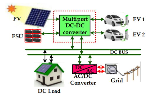
Different ratings of sources and batteries are connected through a multiport converter. Multiport converters are designed with DC interconnection, facilitating the direct use of DC power for EV charging from DC sources. The PV side DC/DC boost converter can be controlled with the MPPT control technique. Even if direct DC power is available at the DC interconnection, there is a requirement for fast charging, which can be achieved through the converter control. The converter is used to interface EV loads, which are unidirectional or bidirectional based on requirement. When the charging side is bidirectional, this can be operated in both buck and boost mode.
Charging Station Standards and Levels
Standard | Scope |
| Type |
SAEJ1772 | Define connectors for AC charging | Conductive | 2010 |
SAE J2293-2 | Communication network between electric vehicle supply equipment (EVSE) and EV; this communication follows an Enhanced Transmission Selection (ETS) network | Conductive | 2014 |
SAE J2847-1 | Provides standard communication between the utility grid and plug-in electric vehicles | Conductive | 2010 |
SAE J2847-2 | This standard defines an off-board conductive DC charger and its communication with plug-in electric vehicles. | Conductive and Inductive | 2015 |
SAE J2954 | This defines a wireless power transfer of all types of plug-in electric vehicles and its coil alignment methodology | Inductive | 2020 |
IFC 61980-3 | Defines the magnetic field-based wireless power system and its specific requirements | Inductive | 2019 |
IEC TS 62840-1 | Gives a general overview for battery swap systems | Battery swapping | 2016 |
IEC 61851-1 | Defines EVSE when it is charging from the voltage range of 1000V to 1500 V AC or DC, including on-board rechargeable energy storage systems (RESS) | Conductive | 2017 |
IEC 61851-24 | Defines a digital communication between a DC charging station and an EV | Conductive | 2014 |
IEC 60364 | Describes power generation and distribution of electrical charging station installations in buildings | Conductive and Inductive | 2017 |
IEE 2030.1.1-2015 | DC quick charger for use with electric vehicles | Fast charging | 2016 |
Power Factor Correction (PFC) single-phase AC/DC converters are used in several power electronics applications as full wave control rectifiers improving power quality and providing high standards of efficiency. Many papers dealing with the description or use of such topologies have been published in recent years; however, a review that describes and organizes their specific details has not been reported in the technical literature. A categorization of bridge, semi-bridgeless, and bridgeless, in accordance with the construction characteristics, was carried out in order to unify the technical terminology. Benefits and disadvantages are described and analyzed in detail. Furthermore, a comparison performance in terms of PFC, Total Harmonic Distortion (THD), power capacity, electromagnetic compatibility (EMC), number of elements, and efficiency is included.
BBC topologies with PFC based on Boost converter are presented in this section. BBC converters are mainly composed of a full rectifier bridge; however, all BBC topologies presented in this section need a line EMI filter between the feeding source and the bridge to comply with international normative regarding THDi (lower than 6%), regardless of the control system. Nevertheless, sizing of the EMI filter depends on the number of switches, control strategy, voltage level, power level, and paths to handle the converter currents.
BBC Topologies
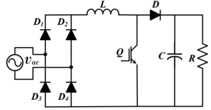
Figure shows the conventional BBC topology where (vac) is the electrical grid or feeding source. The rectification is performed by means of the diode bridge (D1, D2, D3 and D4). Inductor (L) and capacitor (C) interchange energy while diode (D) prevents reverse currents. Resistor (R) is the load that is feeding through a regulated voltage from the DC bus. Control structure is usually implemented by using a cascade PI structure for regulating the DC bus and also performing PFC. The conventional BBC is the most common topology used in low voltage and power applications due to its reduced number of components. However, when medium and high voltage converters are required, power losses must be taken into account in the design process for obtaining a more accurate estimation of efficiency and gains of the system. The importance of soft switching for medium and high voltage and power applications of BBC. A review concerning soft switching techniques with snubber circuits to reduce power switching losses in BBCs was presented. This work analyzes four main aspects:
(1) application for low voltage;
(2) behavior in Discontinuous Conduction Mode (DCM) and Continuous Conduction Mode (CCM);
(3) contrast between Zero Voltage Switching (ZVS), Zero Voltage Transition (ZVT), and Zero Current Switching (ZCS) techniques; and
(4) comparison between MOSFET and IGBT switching technologies.
It should be noted that there are switch technologies with better performance than conventional IGBTs and MOSFETs. These technologies include Gallium Nitride (GaN) switches and Silicon Carbide (SiC) MOSFET switches. GaN and SiC technologies can be used (recommended) in frequencies between 100 KHz and 200 KHz, so that GaN and SiC switches present better efficiency (lower losses) than conventional IGBTs and MOSFETs. More information concerning these switch technologies is available in [48–50]). In general terms, switching with ZVS or ZCS increases the switch useful life. Resonant BBC topology that operates with ZVS or ZCS can be implemented by adding an LC circuit to BBC conventional topology. The aforementioned resonant LC circuit requires an additional switch (a second one) to introduce an inductor to the converter circuit for providing an additional path with zero impedance where the current and voltage do not strongly change their values
The BBC converter is directly connected to the AC supply, so its diodes and power switches inject harmonics and produce noise; then, an EMI filter is required. A design of an EMI filter for a medium power BBC, where results show a reduction of the Common Mode (CM) and Differential Mode (DM) noise when high switching frequency is needed. The EMI filter with classical linear PID control can reduce THDi to normative ranges; nevertheless, limitations of PID control (slow and tuning around of an operation point) can reduce its efficiency, increasing THDi and causing poor dynamic performance when the converter operates out of its design range this can be solved with nonlinear controllers or PID hybrid control techniques. For example, a modulation technique for the BBC that can operate in DCM or CCM, exhibiting a high PF and low THDi over a wide range of input voltage and load. The conventional BBC topology can be modified.
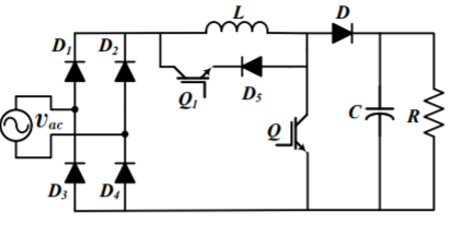
Figure shows the BBC with pseudo-continuous conduction mode where diode D5 and switch Q1 were added in parallel with L. This modification increases dynamic behavior in transients and reduces stress in L by current circulation. Nevertheless, the addition of two semiconductors introduces two issues: (1) the increasing of losses because of the addition of more elements and (2) a complex control strategy to control Q1. This converter modification presents low ripple in DCM and CCM operation for low power application. Another modification to this topology, where two capacitors and inductors were added between the feeding source and the rectifier bridge. This converter presents low THDi and high efficiency with cascade PID control for low voltage and power application. Nevertheless, the additional components increase its implementation cost.
Conventional Interleaved BBC
An interleaved BBC converter has several boost converters connected between the rectifier bridge and DC link capacitor for providing current levels, which improves power quality; consequently, ripple current in input is reduced. In addition, the levels make it possible to reduce the size of inductors, diodes, and circuit switches since thermal stress is reduced. An interleaved BBC converter is recommended for regulating the DC voltage in medium voltage applications since it provides voltage levels in the DC link bus; however, it is not recommended for high voltage applications since power losses and EMI issues are high due to the rectifier bridge. In medium voltage, a robust filter is necessary (EMI filter with several stages) between the AC power supply and the converter; in addition, the use of resonant circuits is recommended for each level for providing soft switching which reduce losses. Figure corresponds to the interleaved BBC converter that is composed of two stages which is commonly implemented in industrial applications. In a methodology for the design of inductors, capacitors, diodes, and power switches. The authors also included the design of the EMI filter. Simulation and experimental results presented an efficiency of around 97% and a power factor up to 0.995.
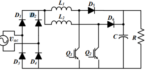
The conventional Interleaved BBC with two states can be modified. The authors proposed to move switches and inductors before the rectifier bridge. Simulation results presented THDi into a normative range with classical PI control for applications in low voltage and power. In addition, operation in DCM and CCM was considered, obtaining an efficiency greater than 96%.
Conventional Hybrid Interleaved PFC Topology
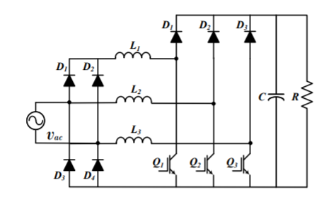
Based on a Boost Converter An interleaved hybrid BBC topology with three levels; please see Figure. This converter may feature an efficiency around 97% when using a PI controller. The authors reported that THDi normative is reached when an EMI filter is used. Basically, currents flow between the branches of the converter, allowing not only the reduction of the ripple current and but also the losses when compared with the interleaved converter of two levels; nonetheless, the addition of a third branch increases its cost. In general terms, this converter is suggested for medium voltage applications because of its low ripple and THDi compared to the conventional BBC converter. In addition, this three-level topology is also recommended in low-voltage applications—this together with independent soft switching circuits considering an independent design control for each switch. The interleaved hybrid BBC topology complies with approximately the same function as the interleaved topology then, the interleaved topology is recommended instead of the hybrid one considering that the hybrid is limited by three states.
Conventional PFC Topology with Bidirectional Switch
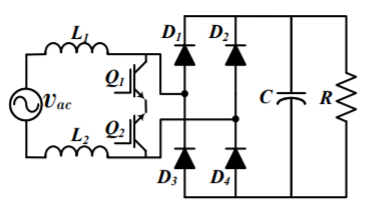
Figure shows the BBC Conventional PFC Topology with Bidirectional Switch. In this topology, inductors L1 and L2 (L1 = L2) are used as coupling inductors, while the bidirectional switch composed of Q1 and Q2 is on the AC side of the converter. For an appropriate operation, D1 and D4 must be fast-recovery diodes. This topology permits the reduction of the common mode noise; however, an EMI filter in the input of the converter is still necessary. One advantage is that the same control signal can be used for controlling Q1 and Q2. It is important to mention that Q1 and Q2 must be installed in inverted order to avoid reverse currents in the operation when both switches are open. In addition, stages of control and power should be isolated. In this topology, a resonant circuit for soft switching in order to reduce switching power losses s recommended.
Case study of power electronics in electric vehicle
This section presents a review regarding the different technologies of road EVs (i.e., vehicles equipped with an electric power-train, which are normally used to transport people or goods by road). In such road EVs, power electronics systems are used to drive the electric machine and charge the battery. In this manner, reviews are presented regarding technology and power electronics structures for EVBC (including the auxiliary battery), traction systems, inductive wireless charging systems, and unified traction and EVBC.
Power Electronics for Battery Charging Systems EV battery chargers (EVBC) are classified into two main groups in relation to their position to the EV, namely on-board or off-board, i.e., inside or outside the EV. By comparing both approaches, it is possible to identify advantages and disadvantages of each charging architecture. For instance, an on-board EVBC offers more flexibility in terms of the possibility of charging the battery at different places, but currently has its charging power limited to a few kW, besides representing an additional weight to the EV. On the other hand, an off-board EVBC is installed in a specific place (public or private) and the EV must travel there to perform the battery charging, but the charging power can be higher, up to dozens or hundreds of kW. Both on-board and off-board EVBCs are constituted by power electronics stages in order to guarantee a proper interface between the power grid and the EV battery.
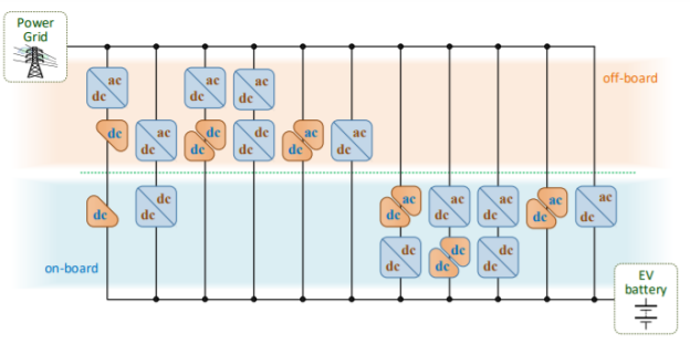
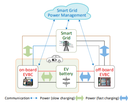
Therefore, and considering the wide variety of power electronics converters, several perspective can be adopted. The most common structures are based on alternating current–direct current (ac-dc) converters guaranteeing a sinusoidal grid current (i.e., preserving power quality on the power grid side) and a dc–dc converter guaranteeing controlled current and voltage on the EV battery (i.e., preserving the battery lifetime), in both on-board and off-board cases. However, other structures can be adopted, including the possibility of single power stage structures. A classification of the different structures, based on single or double power stages, is presented in Figure above.
As emphasized, this classification considers the on-board and off-board possibilities. As an illustrative example, Figure below shows an EV considering both on-board and off-board EVBCs and the respective interface with the power grid. As shown, the on-board EVBC is connected to the power grid through a single-phase interface with the possibility of a bidirectional power flow, while the off-board EVBC is connected to the power grid through a three-phase interface, also considering the possibility of a bidirectional power flow, allowing both G2V and V2G operation modes. This is an increasingly more important feature for smart grids and smart homes, although it normally implies in a more complex implementation of the power stages.
This topology has the main advantage of using only one switching device, still guaranteeing the operation with sinusoidal current and unitary power factor. This topology is shown in Figure a. On the other hand, in a future perspective of electric mobility as a support for the smart grid, a bidirectional operation is essential, in which the four-quadrant ac-dc converter is used as the main topology (i.e., a bidirectional full-bridge).
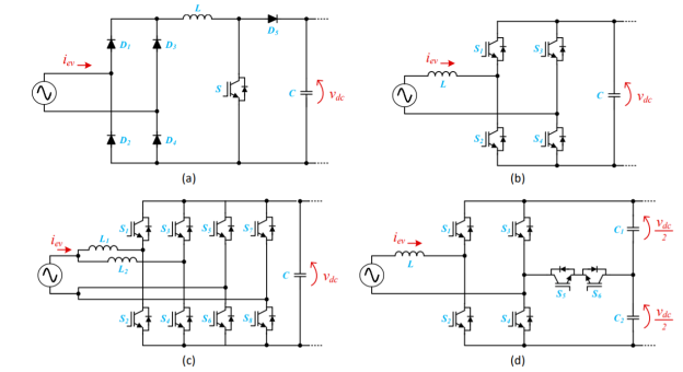
This converter, shown in Figure b, allows bidirectional operation (G2V and V2G modes) without neglecting the sinusoidal current and the unitary power factor. These two topologies are more commonly used. However, when the main objective is to reduce the need for passive filters coupled to the power grid and the maximum current in each semiconductor, to maintain the characteristic of bidirectional operation, the main choice lies in interleaved type topologies. Figure 3c shows the most common bidirectional interleaved fullbridge ac-dc topology, consisting of two four-quadrant ac-dc converters (i.e., dual-phase interleaved topology). When the main objective is to reduce the maximum voltage applied to each semiconductor, as well as to reduce the requirements of passive filters coupled to the power grid, the main choice lies in multilevel topologies. Figure d shows one of the most common multilevel bidirectional ac-dc topology (i.e., a topology of five voltage levels). Communication EV battery off-board EVBC Power (slow charging) Power (fast charging) Smart.
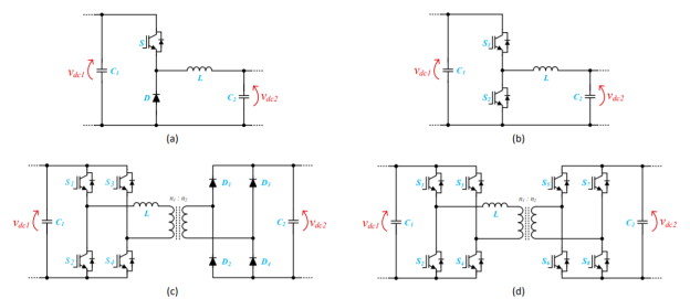
When focusing on unidirectional converters for the back-end stage, the main topology is based on the buck-type dc–dc converter. This converter, shown in Figure a, is easily controllable, as it only has one switching device, and allows the fundamental requirements of battery charging to be met, i.e., charging with constant current (CC) and constant voltage (CV) stages. Additionally, when the objective is to guarantee operation in bidirectional power mode, the main topology that can be used is the half-bridge dc–dc converter. This converter is shown in Figure b. This topology operates in buck mode when it is necessary to charge the batteries (i.e., G2V mode), and operates in boost mode when it is necessary to discharge the batteries (i.e., V2G mode). This topology has as an added value the possibility of guaranteeing the battery charging in CC-CV mode, as well as controlling the battery discharge, which can use CC control algorithms or constant power discharge algorithms. As is easy to observe, only one switching device is controlled in each operating mode (i.e., one in buck mode and another in boost mode), providing added value for the optimization of the converter efficiency. However, this converter is non-isolated. Focusing on this last point, when it is necessary to guarantee galvanic isolation, the main topology that can be used is shown in Figure c. This topology is simple to control, but only allows unidirectional operation. With this topology, it is possible to control the battery charging process, mainly ensuring controllability in CV mode. On the other hand, when it is pertinent to guarantee the operation in bidirectional mode, the logical option is to use the topology presented in Figure d, which is similar to that of Figure c, but in which the converters are fully controlled on both dc sides, being called a dual active bridge. With this last topology, it is possible to either charge (i.e., G2V mode) or discharge (i.e., V2G mode) the battery in a similar way to the topology shown in Figure b.
Case study of power electronics in photovoltaic solar system
Solar energy has the ability to be one of the most relevant forms of renewable energy in the future. In view of the inexhaustible potential of solar energy, it is worth remembering that photovoltaic energy is the most promising alternative to the global energy crisis. However, significant roadblocks such as supply inconsistency, resource place, and the expense of clean energy materials are stopping it from becoming a common energy source. Our job is divided into three parts. First, a summary of PV systems is given. The proposed mathematical model is discussed in the second section. Finally, in the third segment, we present and analyse the simulation results obtained using MATLAB tools.
Atechnique for grid-connected networks utilising renewable energy Through simulating the device in real time, the process allows quick prototyping of control schemes and power converter modules. The system's elements, such as the energy source (photovoltaic array), converters, filters, sensors, and control algorithms, are modelled in FPGA ICs, which decreases cost and time-to-market. FPGA systems are often used in digital control applications. The tools available on the FPGAs used for preliminary testing could be adequate to model the whole framework. With very advanced triggering tools, FPGA debugging tools allow observation of various signals from the evaluated power system (as a result of the control). In contrast to traditional simulation tools, the presented form of simulation through the use of a hardware model of the power system allows more precise verification of control algorithms such as MPPT or anti-islanding. The paper proposes a real-time simulation approach based on FPGAs for control verification of power electronic converters in grid connected systems utilising photovoltaic energy. The findings described here were obtained by the use of FPGA-based models (photovoltaic source, power electronic converters, etc.). And filters) of the power system, both of which are controlled by FPGAs. This demonstrates the value of modelling control circuits prior to their use in power systems, which improves operating protection, reduces time to market, and lowers deployment costs. Additionally, it allows the simulation of a wide range of external situation situations that influence the operation of the conversion device (e.g. Irradiation or temperature of PV source, turning off the grid). The Connected Photovoltaic (PV) device, which uses the Hypersteg Current Integrator to serve the electric grid. We can create a MATLAB simulation software of a utility to depict a grid-connected photovoltaic power system in a distribution power network. These papers attempt to describe the steady-state and intermittent reaction of gridconnected solar power systems. These methods help to manage current, provide power factor, and derive energy from gridconnected PV systems. As a result, the two forms of the solar PV design actions described in this paper have been combined into one. The performance of the solar PV systems is both the direct current and the inverter monitors the utility current. Often, by using hysteres power, overall harmonic distortion is reduced.
The main aim is to demonstrate how the model design of dynamic systems, especially in the field of power electronics systems, can be very useful for use in MatLab. Two cases of energy conversion are described: I a slip energy recovery device (SER) and ii) a fuel cell (FC) electronic power conversion system. In all scenarios, the process energy must be regulated and configured to maximise device performance. The chapter describes how MatLab/Simulink is adapted to solve the problems of determining design specifications, designing multiple models of components for physical evolution, and how engineers may ensure that the final output meets the requirements by the integration of different sub structures. The chapter illustrates the usage of a single PC to measure every power supply and the production firms will minimise the sum of experimental testing and thereby save a lot of money by analysing simulation data. Information of the specifications and application are addressed with each case study, and validation findings are provided to infer the benefits of MatLab / Simulink modelling processes. MatLab/Simulink is in reality seen to be an accurate modelling technique and useful for integrating and speedy prototyping when developing electric engineering systems that involve accurate models of components and subsystems. In the first example, a short description is given about the SER system's circuit configuration and the regulation is carried out in MatLab/Simulink. The author's definition of electrical generation systems focused on MatLab/Simulink is explored in this portion. Through explaining the development of MatLab, MatLab is seen to be a useful method for the computer study of electrical systems to construct physically operated systems. In the first case, the installation and regulation of a traditional power electronics and electric drives SER device was studied. In the second example, a slightly different device design process is chosen and the findings are used for experimental validation.
Harmonic compensation will be described in this article. A PV series, a converter from dc to dc buck and a dc to ac inverter are included in the grid linked PV device simulator model. PV device linked to the Grid is a renewable energy supply system connected to the power grid. Energy sources worldwide are widely used for electricity production much like fossil fuels and an atomic reaction field. However, the combustion of energy production through fossil fuels and nuclear areas is commonly utilised. We're more likely to get I-V & P-V model features. This are sometimes desired by a nonlinear mathematical equation. In this paper, different parameters must be taken into account and configured to achieve most electricity production while building a PV grid linked device. Solar PV device is for home appliances, company instrumentalities, lighting, lightning for any kind of building used only for grid-connected electricity. In addition, this analysis indicates that the radiation of the sun increases the production capacity of the PV panel as the requirement for load increases. The PV model is able to increase the system's ability. This may be true In the future, the theoretical result in order to achieve it would be contrasted with realistic findings correlated with the observation.
In the outdoor output of poly-crystalline (poly-Si) pv modules, the effect of solar radiation, atmospheric temperature and clearness indicators is taken into account. The article underlines how the Clearness Index for the Integrated Photovoltaic Device Building (BIPV) in Malaysia impacts energy production. MATLAB/SIMULINK simulation was applied with the data actually tracked. A 45.36 kWh device case study using a polycristal line modulum shows that the energy efficiency is 7,23% to 8,52% and the clarity index is 0,55 and therefore the energy production has been determined by the clearance index as well as the temperature and solar irradiance
A mathematical model in this analysis to simulate in roll action conditions, the conduct of a photovoltaic generator. This model demonstrated both the I-V curve and the P-V curve effects of incident control, temperature and series resistance. We also showed the effective technique of perturbing and observing algorithms for maximising the operation of the photovoltaic generator. In order to maximise. The performance of the photovoltaic device, the production capacity of a photovoltaic generator is associated with multiple climate conditions such as temperature and sunlight. This work introduces the modelling of a power point monitoring photovoltaic device (MPPT). The working of photovoltaic systems is faced with an MPPT focused on a P&O technique, all performed using Matlab, and the enhancement of its performance taking into consideration rapid changes in weather conditions. The findings of the simulation indicated that the operation point oscillated around the highest power point, and this is relative to the differences in lighting of the event.
References:
- Power Electronics by M.D Singh Second Edition
- Fundamentals of Power Electronics by S.K Bhattacharya.