Unit-3
Induction machines
Q1 Explain the Construction of squirrel cage induction motor?
Ans:
1. Squirrel cage motor is one of the types of induction motors. In order to generate motion, it hardens electromagnetism.
2. As the output shaft is connected to the rotor inner component which is looking like a cage. Hence it is called squirrel cage.
3. The two-end caps i.e, circular in shape are joined by rotor bars. These are acted based on the EMF i.e, generated by the stator.
4. This EMF is also generated outer housing that is made of laminated metal sheets and wire coiling.
- The two main parts of any type of induction motor are the stator and the rotor. The squirrel cage is a simple method of pulling an electromagnetic induction effect.
1. Parts that are required for the construction of squirrel cage induction motor are stator, rotor, fan, bearings.
2. The stator consists of mechanically and electrically 120 degrees apart three-phase winding with metal housing and core. In order to provide the path of low reluctance for flux generated by Ac current, the winding is mounted on the laminated iron core.
3. Rotor converts given electrical energy into mechanical output.
4. The shaft, a core, short-circuited copper bars are the parts of the rotor. In order to avoid hysteresis and eddy currents that are leading to power loss, the rotor is laminated.
5. And I order to prevent cogging, conductors are skewed which also helps to give a good transformation ratio.
6. A fan attached at the back of the rotor for heat exchange helps in maintaining under a limit of the temperature of the motor. For the smooth rotation, bearings are provided in the motor.
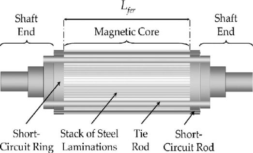
Fig : squirrel cage induction motor
Q2. Explain the types of squirrel cage induction motors in detail?
Ans:
1. Class-A Design
These type motors have low resistance, reactance, slip, and higher efficiency at full load. The main disadvantage is high starting current which is 5 to 8 times of full-load current at rated voltage. These motors are widely used in small ratings for machine tools, centrifugal pumps, fans, blowers, etc.
2. Class B Design
These motors have high reactance and operate 5-150KW range. These motors can be replaced with class A motors for new installations because of its characteristics which are similar to Class A motors and have the same staring current. (Around 5 times the full-load current at rated voltage).
3. Class C Design
These motors are known as double cage motors that high starting torque with the low starting current. Applications of class C motors are, driving air compressors, conveyors, reciprocating pumps, crushers, mixers, large refrigerating machines, etc.
4. Class D Design
These motors are squirrel cage motors with high resistance. Hence, they give high starting torque with the low starting current. These motors have low operating efficiency and limited to drive intermittent loads involved in high accelerating duty and high-impact loads such as punch presses, shears, bulldozers, small hoists, etc.
5. Class E Design
These motors operate with low starting torque, normal starting current, and also low slip at rated load.
6. Class F Design
These motors are operated with low starting torque, low starting current, and normal slip.
Q3. Explain torque slip characteristics of induction motor in detail ?
Ans :
The curve can be described in three modes of operation-
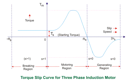
Fig : torque slip characteristics diagram
The torque-slip characteristic curve can be divided roughly into three regions:
1. Low slip region
2. Medium slip region
3. High slip region
A. Motoring Mode
1. In this mode of operation, supply is given to the stator sides and the motor always rotates below the synchronous speed.
2. The induction motor torque varies from zero to full load torque as the slip varies.
3. The slip varies from zero to one. It is zero at no load and one at standstill. From the curve it is seen that the torque is directly proportional to the slip.
4. That is, more is the slip, more will be the torque produced and vice-versa. The linear relationship simplifies the calculation of motor parameter to great extent.
B. Generating Mode
1. In this mode of operation induction motor runs above the synchronous speed and it should be driven by a prime mover.
2. The stator winding is connected to a three phase supply in which it supplies electrical energy. Actually, in this case, the torque and slip both are negative so the motor receives mechanical energy and delivers electrical energy.
3. Induction motor is not much used as generator because it requires reactive power for its operation.
4. That is, reactive power should be supplied from outside and if it runs below the synchronous speed by any means, it consumes electrical energy rather than giving it at the output. So, as far as possible, induction generators are generally avoided.
C. Braking Mode
1. In the Braking mode, the two leads or the polarity of the supply voltage is changed so that the motor starts to rotate in the reverse direction and as a result the motor stops.
2. This method of braking is known as plugging. This method is used when it is required to stop the motor within a very short period of time.
3. The kinetic energy stored in the revolving load is dissipated as heat. Also, motor is still receiving power from the stator which is also dissipated as heat.
4. So as a result of which motor develops enormous heat energy. For this stator is disconnected from the supply before motor enters the braking mode.
5. If load which the motor drives accelerates the motor in the same direction as the motor is rotating, the speed of the motor may increase more than synchronous speed.
6.In this case, it acts as an induction generator which supplies electrical energy to the mains which tends to slow down the motor to its synchronous speed, in this case the motor stops. This type of breaking principle is called dynamic or regenerative breaking.
Q4. Define Starting and maximum torque ?
1. Maximum torque
The developed torque is maximum when the rotor resistance per phase is equal to the rotor reactance per phase under running conditions.
2. Starting torque
Starting torque is the torque transferred by the shaft coupling during run-up (see Start-up process). It is calculated based on the ratio of power (P) to angular velocity (ω) and is represented as a rotational speed function.
Q5. Explain in detail Phasor diagram of induction machines?
Ans:
Induction Motor Phasor Diagram at Standstill Condition:
Before going into the phasor diagram, there are some important points to be taken care:
Per phase value of induced emf E1 in the stator winding is given as below
E1 = √2πf1kw1N1Ø
Where f1 = supply frequency
N1 = Number of series turns per phase
Ø = resultant air gap flux per pole
kw1 = Stator winding factor
Per phase value of induced emf E2 in rotor winding is given as
E2 = √2πf2kw2N2Ø
where f2 = frequency of induced emf in rotor = sf1
N2 = Number of series turns per phase
Ø = resultant air gap flux per pole
kw2 = Rotor winding factor
1. Total air gap mmf Fr of induction motor is the sum of stator mmf (F1) and rotor mmf (F2).
2. Magnetizing current Im taken by stator winding from the supply always remains in phase with the resultant flux Ø.The induced emf always lags behind the resultant flux Ø by 90°.
3. Now we are at a stage to draw the induction motor phasor diagram. Let us take the resultant air gap flux Ø as the reference. This flux Ø will be in phase with the resultant mmf Fr. Also, the induced emf E1 and E2 in stator and rotor winding will lag behind the Ø by 90°. This is shown in the below phasor diagram of induction motor.
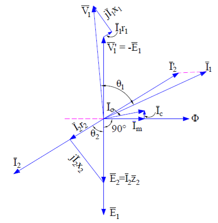
Fig : Phasor diagram of induction motor
4. Since the rotor mmf counteracts the stator produced mmf as per lenz’s law, therefore stator takes extra current from supply to counterbalance the effect of rotor current. Therefore under normal condition,
Stator mmf = Rotor mmf
N1’I2’ = N2’I2
where N1’ and N2’ are the effective stator and rotor turns per phase.
5. This component of stator current is called the load component. In addition to load component, stator also takes magnetizing current Im to build magnetic flux in the air gap.
6. Thus the total stator current I1 = I2’ + Im. This is shown in the above phasor diagram. I2’ is shown opposite to the rotor current I2 for the reason discussed above.
7. At standstill condition, E2 = I2 (r2 + jx2). The core loss component of stator current Ic is in phase phase with V1’ or –E1. At standstill condition, the friction and windage loss is zero, therefore the stator no load current is given as
I0 = Im + Ic
Since stator applied voltage V1 must balance the stator back emf V1’ or -E1, stator impedance drop I1(r1 + jx1), therefore we can write
V1 = V1’ + I1(r1 + jx1) ……(1)
Similar equation exists for rotor circuit and can be written as
E2 = I2 (r2 + jx2) ……..(2)
8. The above equations are applied for drawing induction motor phasor diagram as shown in above figure. It can be easily seen from the above phasor diagram that, the power factor (cosɵ) of induction motor at starting is very poor as ɵ is large.
- Induction Motor Phasor Diagram at Full Load Slip:
1. At full load, the slip s of induction is low. The stator voltage equation (1) do not changes when the motor is loaded. But the rotor voltage equation changes with slip. The rotor induced voltage at any slip s becomes sE2 and the rotor circuit reactance becomes sx2. Therefore,
sE2 = I2 (r2 + jsx2)
2. The above rotor equation when implemented, the induction motor phasor diagram will becomes different from the phasor at standstill condition. The induction motor phasor at full load slip s is shown below.
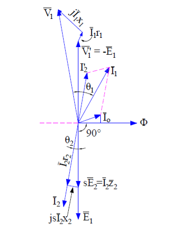
Fig : Phasor diagram at full load
3. Since at full load condition, some friction and windage loss will exists. This means that stator will have to draw some extra current from the supply main to provide this additional loss.
4. Therefore the total no load current I0 taken by stator is the sum current Ifc and Im. It can be seen from the above phasor diagram that power factor of induction motor improves.
5. Generally at full load the power factor ranges in between 0.8 to 0.9.
Q6. Classify the losses in induction motor in detail?
Ans
A. Iron or Core Losses
1. Iron or core losses are further divided into hysteresis and eddy current losses. Eddy current losses are minimized by using lamination on core.
2. Since by laminating the core, area decreases and hence resistance increases, which results in decrease in eddy currents. Hysteresis losses are minimized by using high grade silicon steel.
3. The core losses depend upon frequency of the supply voltage. The frequency of stator is always supply frequency, f and the frequency of rotor is slip times the supply frequency, (sf) which is always less than the stator frequency.
4. For stator frequency of 50 Hz, rotor frequency is about 1.5 Hz because under normal running condition slip is of the order of 3 %. Hence the rotor core loss is very small as compared to stator core loss and is usually neglected in running conditions.
B. Mechanical and Brush Friction Losses
1. Mechanical losses occur at the bearing and brush friction loss occurs in wound rotor induction motor. These losses are zero at start and with increase in speed these losses increases.
2. In three phase induction motor the speed usually remains constant.
3. Hence these losses almost remains constant.
C. Variable Losses
1. These losses are also called copper losses. These losses occur due to current flowing in stator and rotor windings.
2. As the load changes, the current flowing in rotor and stator winding also changes and hence these losses also changes. Therefore these losses are called variable losses.
3. The copper losses are obtained by performing blocked rotor test on three phase induction motor. The main function of induction motor is to convert an electrical power into mechanical power.
Q7. Derive equation for Efficiency?
Ans:
Efficiency of 3 phase induction motor:
Efficiency is defined as ratio of output to that of input

Rotor efficiency of 3 phase induction motor

Gross mechanical power developed /rotor input

Three phase induction motor efficiency

Three phase induction motor efficiency

Q8. Explain in detail Variations by parameters in Torque-Speed Characteristics?
Ans:
1.WRT to diagram In a previous article for torque-speed characteristics, we studied the different parameters related to that curve.
2. Suppose if we have such rotor that has a higher value of the rotor resistance Rr due to this higher value of the resistance the starting torque will also larger, as torque is higher so the slip will also higher.
As we know that this equation.
P conv = (1-s) PAG
3. Due to the higher value of the slip, the power converted from the electrical to mechanical will have less value, due to less power conversion the efficiency of the motor will decreases.
4. From that, we can conclude that such a motor that has higher rotor resistance, has larger starting torque but less efficiency.
5. If the resistance of the rotor is less than the starting torque will also less but the efficiency of the motor will be larger than the motor that has a high value of the rotor’s resistance.
6. The manufacturer of the motor always tries to cooperation among the differing requirements of higher initial torque and suitable efficiency.
7. The solution for this is that if we put some additional resistance in the rotor of the wound motor during its starting for higher torque then during its normal working remove this resistance for good efficiency.
8. But there is a problem for this condition that the wound rotor motor is costly, its repairing price is also larger, need a multifaceted automatic control circuitry than cage rotor motors.
9. Similarly, it is sometimes significant to entirely cover a motor when it is sited in a risky or fiery atmosphere, and this is calmer to do with an entirely self-contained rotor.
10. It would be pleasing to add additional rotor resistance at initial and to eliminate it during normal operation without automatic control circuitry.
11. In the given figure you can see the 2 wound rotor motors characteristic curves, one motor has high resistance rotor and second has less resistance rotor.
12. At higher slip value, the anticipated motor should act like the higher-resistance wound-rotor motor curve and at less slip, it should act like the less-resistance wound-rotor motor curve.
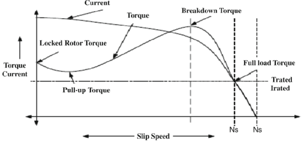
Fig : Variations by parameters in Torque-Speed Characteristics
Q9. Explain the concept of speed control in induction machine?
Ans:
Speed control of induction motors can be done in six methods which are
1. Pole changing
2. Stator voltage control
3. Supply frequency control
4. Eddy current coupling
5. Rotor resistance control
-concept
1. We know that the speed of the induction motor is inversely proportional to number of poles. So it is possible to increase or decrease the speed of the induction motor if the number of the poles are decreased or increased respectively.
2. The motor in which the provision of changing the number of poles is present, they are called ‘pole changing motor’ or ‘multi speed motor’.
3. Another method of controlling the speed of induction motor drives is the stator voltage control. Stator voltage is directly responsible for the rotating speed of the rotor.
4. Torque is proportional to voltage squared and the current is proportional to the voltage. So, if the stator voltage is reduced the speed reduces and similarly if the stator voltage is increased the speed also increases.
5. The speed of an induction motor is proportional to the product of the supply frequency and air gap flux.
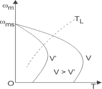
Fig : speed control graph
Q10. Explain Generator operation in detail?
Ans:
Induction machines are sometimes used as a generator. These are known as induction generators or asynchronous generators. So under what conditions an induction machine will behave as an induction generator?
An induction machine will behave as an induction generator when:
1. Slip becomes negative due to this the rotor current and rotor emf attains negative value.
The prime mover torque becomes opposite to electric torque.
2. Now let us discuss how we can achieve these conditions. Suppose that an induction machine is coupled with the prime mover whose speed can be controlled.
3. If the speed of the prime mover is increased such that the slip becomes negative (i.e. speed of the prime mover becomes greater than the synchronous speed).
4. Due to this, all the conditions that we have mentioned above will become fulfilled and the machine will behave like an induction generator. Now if the speed of the prime mover is further increased such that it exceeds the negative maximum value of the torque produced then the generating efficiency of the generator vanishes.
5. Clearly, the speed of the induction generator during the whole operation is not synchronous, therefore the induction generator is also called a synchronous generator.
6.An induction generator is not a self-excited machine. Therefore in order to develop the rotating magnetic field, it requires magnetizing current and reactive power.
7. The induction generator obtains its magnetizing current and reactive power from the various sources like the supply mains or it may be another synchronous generator.
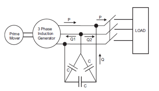
Fig : Generator diagram
Q11. State and explain Power flow diagram ?
Ans :
1.An induction motor converts electrical power supplied to it into mechanical power. The various stages in this conversion are called power transfer stages in an induction motor.
2. The 3-phase power input to an induction motor i.e, stator input is,
Pin = √3 VL IL Cos φ
3. Where VL and IL are the line values of stator supply voltage and current and Cos φ is the power factor of the motor.
4. A part of this power is consumed in stator iron and copper losses. The remaining power is transferred inductively to the rotor through the air-gap. This is called as rotor input P2. Therefore,
P2 = Pin - stator iron and copper losses
5. The rotor losses consist of the majority of copper loss and very small rotor iron loss which are generally neglected. By subtracting the rotor copper losses from P2, we get the gross mechanical power developed by the motor Pm.
Pm = P2 - rotor copper losses
6. A part of Pm is consumed as mechanical losses and the remaining is the power available to the load at the shaft. This is called as Net Output Power of the Motor Pout.
The above stages can be shown diagrammatically called as Power Flow Diagram of Induction Motor.

Fig . Power flow diagram
Q12. State and explain Determination of parameters:
Ans :
1. A stationary pulsating magnetic field might be resolved into two rotating fields, both having equal magnitude but opposite in direction.
2. So the net torque induced is zero at standstill. Here, the forward rotation is called the rotation with slip s and the backward rotation is given with a slip of (2 – s). The equivalent circuit is-
3. In most of the cases the core loss component r0 is neglected as this value is quite large and does not affect much in the calculation.
Here, Zf shows the forward impedance and Zb shows the backward impedance.
Also, the sum of forward and backward slip is 2 so in case of backward slip, it is replaced by (2 – s).
R1 = Resistance of stator winding.
X1 = Inductive reactance of the stator winding.
Xm = Magnetising reactance.
R2’ = Rotor Reactance with referred to stator.
X2’ = Rotor inductive reactance with referred to stator.
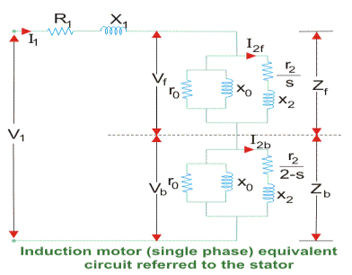
Fig . Equivalent circuit
Unit - 1
Introduction
Introduction
● The term "Automata" is derived from the Greek word "αὐτόματα" which means "self-acting". An automaton (Automata in plural) is an abstract self-propelled computing system that automatically follows a predetermined operation sequence.
● The primary reason behind the development of the automata theory was the development of methods to explain and analyze the complex behavior of separate systems.
Key takeaway:
- The automaton is called the abstract machine.
- It is the analysis of abstract machines and the problems of computation that can be solved by these machines.
Definition − An alphabet is any finite set of symbols.
Example − ∑ = {a, b, c, d} is an alphabet set where ‘a’, ‘b’, ‘c’, and ‘d’ are symbols.
Language
Definition − A language is a subset of ∑* for some alphabet ∑. It can be finite or
Infinite.
Example − If the language takes all possible strings of length 2 over ∑ = {a, b}, then
L = { ab, aa, ba, bb }
Grammar
Simplifying Context Free Grammars
A context free grammar (CFG) is in Chomsky Normal Form (CNF) if all production
Rules satisfy one of the following conditions:
A non-terminal generating a terminal (e.g.; X->x)
A non-terminal generating two non-terminals (e.g.; X->YZ)
Start symbol generating ε. (e.g.; S->ε)
Consider the following grammars,
G1 = {S->a, S->AZ, A->a, Z->z}
G2 = {S->a, S->aZ, Z->a}
The grammar G1 is in CNF as production rules satisfy the rules specified for CNF. However, the grammar G2 is not in CNF as the production rule S->aZ contains terminal followed by non-terminal which does not satisfy the rules specified for CNF.
Key takeaway:
- CNF is a pre-processing step used in various algorithms.
- For generation of string x of length ‘m’, it requires ‘2m-1’ production or steps in CNF.
A production, if its left side occurs on its right side, is called recursive. Production S→aS, for example, is recursive. A manufacturing A → α is recursive indirectly. If a sentence form that includes A is derived from A, then suppose we have the following grammar:
S → b/aA
A → c/bS
Due to the following derivations, the S → aA and A→ bs productions are both indirectly recursive:
S ⇒ aA ⇒ abS,
A ⇒ bS ⇒ baA
A grammar is recursive if either a recursive or indirectly recursive production is included in it.
Derivation
Derivation is a sequence of the laws of development. Via these production laws, it is used to get the input string. We have to take two decisions during parsing. That are like the following:
● The non-terminal that is to be replaced must be determined by us.
● We have to determine the law of development by which the non-terminal would be substituted.
We have two options to assess which non-terminal with the production rule is to be put.
- Left most derivation
The input is scanned and replaced with the development rule from left to right in the left-most derivation. So, we read the input string from left to right in the left-most derivation.
2. Right most derivation
The input is scanned and replaced with the production rule from right to left in the right-most derivation. So, we read the input string from right to left in the right - most derivation.
The Chomsky Hierarchy describes the class of languages that the various machines embrace. The language group in Chomsky's Hierarchy is as follows:
- Type 0 known as Unrestricted Grammar.
- Type 1 known as Context Sensitive Grammar.
- Type 2 known as Context Free Grammar.
- Type 3 Regular Grammar.

Fig 1: Chomsky hierarchy
The above diagram shows the hierarchy of Chomsky. Each language of type 3 is therefore also of type 2, 1 and 0 respectively. Similarly, every language of type 2 is also of type 1 and type 0 likewise.
● Type 0 grammar -
Type 0 grammar is known as Unrestricted grammar. The grammar rules of these types of languages are unregulated. Turing machines can model these languages efficiently.
Example:
- BAa → aa
- P → p
● Type 1 grammar -
Type 1 grammar is known as Context Sensitive Grammar. Context-sensitive grammar is used to describe language that is sensitive to context. The context-sensitive grammar follows the rules below:
● There may be more than one symbol on the left side of their development rules for context-sensitive grammar.
● The number of left-hand symbols does not surpass the number of right-hand symbols.
● The A → ε type rule is not permitted unless A is a beginning symbol. It does not occur on the right-hand side of any rule.
● The Type 1 grammar should be Type 0. Production is in the form of V →T in type1
Key takeaway:
- Where the number of symbols in V is equal to or less than T
Example:
- S → AT
- T → xy
- A → a
● Type 2 grammar -
Type 2 Grammar is called Context Free Grammar. Context free languages are the languages which can be represented by the CNF (context free grammar) Type 2 should be type 1. The production rule is :
A → α
Key takeaway:
- Where A is any single non-terminal and is any combination of terminals and non-terminals.
Example:
- A → aBb
- A → b
- B → a
● Type 3 grammar -
Type 3 Grammar is called Regular Grammar.Those languages that can be represented using regular expressions are regular languages. These languages may be NFA or DFA-modelled.
Type3 has to be in the form of -
V → T*V / T*
Example:
A → xy
Key takeaway:
- The most limited form of grammar is Type3. Type2 and Type1 should be the grammar of Type3.
● Simple expressions called Regular Expressions can readily define the language adopted by finite automata. This is the most powerful way of expressing any language.
● Regular languages are referred to as the languages recognized by certain regular expressions.
● A regular expression may also be defined as a pattern sequence that defines a series.
● For matching character combinations in strings, regular expressions are used. This pattern is used by the string search algorithm to locate operations on a string.
A Regular Expression can be recursively defined as follows −
● ε is a Regular Expression indicates the language containing an empty
String. (L (ε) = {ε})
● φ is a Regular Expression denoting an empty language. (L (φ) = { })
● x is a Regular Expression where L = {x}
● If X is a Regular Expression denoting the language L(X) and Y is a Regular
● Expression denoting the language L(Y), then
❏ X + Y is a Regular Expression corresponding to the language L(X) ∪
L(Y) where L(X+Y) = L(X) ∪ L(Y).
❏ X . Y is a Regular Expression corresponding to the language L(X) .
L(Y) where L(X.Y) = L(X) . L(Y)
❏ R* is a Regular Expression corresponding to the language L(R*)
Where L(R*) = (L(R))*
● If we apply any of the rules several times from 1 to 5, they are Regular
Expressions.
Unix Operator Extensions
Regular expressions are used frequently in Unix:
● In the command line
● Within text editors
● In the context of pattern matching programs such as grep and egrep
Additional operators are recognized by Unix. These operators are used for
Convenience only.
● character classes: ‘[‘<list of chars> ‘]’
● start of a line: ‘^’
● end of a line: ‘$’
● wildcard matching any character except newline: ‘.’
● optional instance: R? = epsilon | R
● one or more instances: R+ == RR*
Key takeaway:
- Regular languages are referred to as the languages recognised by certain regular expressions.
- A regular expression may also be defined as a pattern sequence that defines a series.
In DFA, for each input symbol, one can determine the state to which the machine will move. Hence, it is called Deterministic Automaton. As it has a finite number of states, the machine is called Deterministic Finite Machine or Deterministic Finite Automaton.
An automaton can be represented by a 5-tuple (Q, ∑, δ, q 0 , F), where −
● Q is a finite set of states.
● ∑ is a finite set of symbols, called the alphabet of the automaton.
● δ is the transition function.
● q 0 is the initial state from where any input is processed (q 0 ∈ Q).
● F is a set of final state/states of Q (F ⊆ Q).
Transition function can be defined as:
δ: Q x ∑→Q
Equivalence with regular expression
Successively replacing states and transitions in the DFA graph with transitions labelled with the corresponding regular expressions is one approach to transforming a DFA into an equivalent RE.
Note that any transformation in the DFA is initially de facto labelled with a periodic expression. A new final state should be formed with an ε-transition from each of the previous final states if there are several final states.
Consider the following FA, for instance, with three states.

A transformation labelled with the regular expression ab representing the concatenation of a and b can be substituted for state q1.

Next, with two states and two parallel transitions, consider the following FA.

A single transition labelled with the regular expression a+b representing the union of a and b will replace the two transitions.

Now, consider the following FA, which involves a move to and from the same state.

The Kleene star over a, which can be defined by the standard expression a*, indicates the transition. The two transitions can therefore be replaced by a single transition labelled with the standard expression a*b indicating that a* is concatenated with b.

The mark on that transition is the regular expression equivalent to the original DFA once the FA graph has been decreased to two states (an initial state and a final state) and a single transition.
Key takeaway:
- it has a finite number of states, the machine is called Deterministic Finite Machine or Deterministic Finite Automaton
- Any transformation in the DFA is initially de facto labelled with a periodic expression.
In NDFA, for a particular input symbol, the machine can move to any combination of the states in the machine. In other words, the exact state to which the machine moves cannot be determined. Hence, it is called Non-deterministic Automaton. As it has a finite number of states, the machine is called Non- deterministic Finite Machine or Non- deterministic Finite Automaton.
It has a finite number of states.
Q → Finite non-empty set of states.
∑ → Finite non-empty set of input symbols.
∂ → Transitional Function.
q0 → Beginning state.
F → Final State
Transition function can be defined as:
δ: Q x ∑ →2Q
Equivalence of DFA and NFA
It would seem superficially that deterministic and non-deterministic finite state automata are totally distinct beasts. However, it turns out that they are equivalent. There is a DFA for every language recognized by an NFA that recognizes that language and vice versa.
The NFA to DFA conversion algorithm is relatively simple, even though the resulting DFA is substantially more complicated than the original NFA. I will illustrate this equivalence after the hop and also go through a brief example of converting an NFA to an equivalent DFA.
DFA and NFA Theorem proof -
Let's formally state the theorem we are proving before continuing:
Theorem:
Let the language L ⊆ Σ* be recognized by NFA N = (Σ, Q, q0, F, δ) and assume L.
A DFA D= (Σ, Q ', q'0, F', δ ') exists that also accepts L. (L(N)= L(D)).
We are able to prove by induction that D is equal to N by allowing each state in the DFA D to represent a set of states in the NFA N. Let's define the parameters of D: before we start proofing,
● Q’ is equal to the powerset of Q, Q’ = 2Q
● q’0 = {q0}
● F’ is the set of states in Q’ that contain any element of F, F’ = {q ∈ Q’|q ∩ F ≠ Ø}
● δ’ is the transition function for D. δ’(q ,a ) = Up∈ q δ(p , a)for q ∈ Q’ and a ∈ Σ
It's worth more explaining, I think δ '. Note that in the set of states Q 'in D, each state is a set of states from Q in N itself. Determine the transition δ (p,a) for each state p in state q in Q 'of D (p is a single state from Q). The union of all δ (q, a) is δ(q,a) .
Now we will demonstrate δ’(q0’ , x) =δ’(q0 , x) that for every x i.e L(D) = L (N)
Key takeaway:
- In NDFA, for a particular input symbol, the machine can move to any combination of the states in the machine.
- the exact state to which the machine moves cannot be determined. Hence, it is called Non-deterministic Automaton.
Regular expressions and finite automata have equivalent expressive power:
● For every regular expression R, there is a corresponding FA that accepts the
Set of strings generated by R.
● For every FA, A there is a corresponding regular expression that generates the set of strings accepted by A.
The proof is in two parts:
1. An algorithm that, given a regular expression R, produces an FA A such that
L(A) == L(R).
2. An algorithm that, given an FA A, produces a regular expression R such that
L(R) == L(A).
Our construction of FA from regular expressions will allow “epsilon transitions” (a transition from one state to another with epsilon as the label). Such a transition is always possible, since epsilon (or the empty string) can be said to exist between any two input symbols. We can show that such epsilon transitions are a notational convenience; for every FA with epsilon transitions there is a corresponding FA without them.
Constructing an FA from an RE
We begin by showing how to construct an FA for the operands in a regular
Expression.
● If the operand is a character c, then our FA has two states, s0 (the start state)
And sF (the final, accepting state), and a transition from s0 to sF with label c.
● If the operand is epsilon, then our FA has two states, s0 (the start state) and
SF (the final, accepting state), and an epsilon transition from s0 to sF.
● If the operand is null, then our FA has two states, s0 (the start state) and sF
(the final, accepting state), and no transitions.
Given FA for R1 and R2, we now show how to build an FA for R1R2, R1|R2, and
R1*. Let A (with start state a0 and final state aF) be the machine accepting L(R1)
And B (with start state b0 and final state bF) be the machine accepting L(R2).
● The machine C accepting L(R1R2) includes A and B, with start state a0, final
State bF, and an epsilon transition from aF to b0.
● The machine C accepting L(R1|R2) includes A and B, with a new start state
c0, a new final state cF, and epsilon transitions from c0 to a0 and b0, and
From aF and bF to cF.
● The machine C accepting L(R1*) includes A, with a new start state c0, a new
Final state cF, and epsilon transitions from c0 to a0 and cF, and from aF to a0,
And from aF to cF.
Eliminating Epsilon Transitions
If epsilon transitions can be eliminated from an FA, then construction of an FA
From a regular expression can be completed.
Epsilon transitions offers a choice: It allows us to stay in a state or move to a
New state, regardless of the input symbol.
If starting in state s1, state s2 can be reached via a series of epsilon
Transitions followed by a transition on input symbol x, replacement of the epsilon
Transitions with a single transition from s1 to s2 on symbol x.
Algorithm for Eliminating Epsilon Transitions
A finite automaton F2 can be built with no epsilon transitions from a finite
Automaton F1 as follows:
1. The states of F2 are all the states of F1 that have an entering transition
Labeled by some symbol other than epsilon, plus the start state of F1, which is
Also the start state of F2.
2. For each state in F1, determine which other states are reachable via epsilon
Transitions only. If a state of F1 can reach a final state in F1 via epsilon
Transitions, then the corresponding state is a final state in F2.
For each pair of states i and j in F2, there is a transition from state i to state j on input
x if there exists a state k that is reachable from state i via epsilon transitions in F1,
And there is a transition in F1 from state k to state j on input x.
Key takeaway:
- For every regular expression, there is a corresponding FA that accepts the
Set of strings generated by RE.
- The computer can switch to any combination of states in the NDFA.
- Epsilon closure for a given state X is a set of states that can only be reached with (null) or ε moves from states X, including state X itself.
- When the computer is given a single input to a single state, it goes to a single state in DFA.
Regular languages are closed under a wide variety of operations.
- Union and intersection
Pick DFAs recognizing the two languages and use the cross-product construction to build a DFA recognizing their union or intersection.
- Set complement
Pick a DFA recognizing the language, then swap the accept/non- accept markings on its states.
- String reversal
Pick an NFA recognizing the language. Create a new final state, with epsilon transitions to it from all the old final states. Then swap the final and start states and reverse all the transition arrows.
- Set difference
Rewrite set difference using a combination of intersection and set complement.
- Concatenation and Star
Pick an NFA recognizing the language and modify.
- Homomorphism
A homomorphism is a function from strings to strings. What makes it a homomorphism is that its output on a multi-character string is just the concatenation of its outputs on each individual character in the string. Or, equivalently, h(xy) = h(x)h(y) for any strings x and y. If S is a set of strings, then h(S) is {w : w = h(x) for some x in S}.
To show that regular languages are closed under homomorphism, choose an arbitrary regular language L and a homomorphism h. It can be represented using a regular expression R. But then h(R) is a regular expression representing h(L). So h(L) must also be regular.
Notice that regular languages are not closed under the subset/superset relation. For
Example, 0 * 1 * is regular, but its subset {O n 1 n : n >= 0} is not regular, but its subset {01, 0011, 000111} is regular again.
Theorem -
Let L be a regular language. Then a constant c' exists such that for every string w in L
|w| ≥ c
We are able to split w into three strings, w=xyz, so that
● |y| > 0
● |xy| ≤ c
● For all k ≥ 0, the string xyKz is also in L
Application of Pumping Lemma
It is important to apply Pumping Lemma to show that certain languages are not normal. It can never be used to illustrate the regularity of a language.
● If L is regular, it satisfies Pumping Lemma.
● If L does not satisfy Pumping Lemma, it is non-regular.
Method for demonstrating that a language L is not regular
● We have to assume that L is regular.
● The pumping lemma should hold for L.
● Use the pumping lemma to obtain a contradiction −
● Select w such that |w| ≥ c
● Select y such that |y| ≥ 1
● Select x such that |xy| ≤ c
● Assign the remaining string to z.
● Select k such that the resulting string is not in L.
Therefore, L is not regular.
Example:
Prove that L = {aibi | i ≥ 0} is not regular.
Sol:
● At first, we assume that L is regular and n is the number of states.
● Let w = anbn. Thus |w| = 2n ≥ n.
● By pumping lemma, let w = xyz, where |xy| ≤ n.
● Let x = ap , y = aq , and z = arbn , where p + q + r = n, p ≠ 0, q ≠ 0, r ≠ 0. Thus |y| ≠ 0.
● Let k = 2. Then xy2z = apa2qarbn.
● Number of as = (p + 2q + r) = (p + q + r) + q = n + q
● Hence, xy2z = an+q bn . Since q ≠ 0, xy2z is not of the form anbn .
● Thus, xy2z is not in L.
Hence L is not regular.
It is possible to create infinitely many finite state automata for a given regular language L to accept L. The answer is that there will be a loop in the transition diagram centered on a given DFA M1 . To have more states and L(M1) = L(M2) = L, we can create a new DFA M2. And we can create a DFA M3 with even more states and L(M3) = L from DFA M2.
For instance, given a DFA M1, we can create a DFA M2 to have more states and
L(M1) = L(M2) = L.
Example: The following two DFA's are identical to M1 and M2. The collection above the alphabet Σ = {0,1} is accepted by {0n | n>0} both machines.
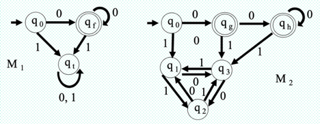
Fig 2: DFA diagram
Machine M2 states q1 , q2 and q3 are identical, we can combine these three states in one state as qt in machine M1.
The state qg and qh of the M2 machine are identical, these two states can be combined in one state as qf in the M1 machine.
References:
- Harry R. Lewis and Christos H. Papadimitriou, Elements of the Theory of
Computation, Pearson Education Asia.
2. Dexter C. Kozen, Automata and Computability, Undergraduate Texts in Computer Science, Springer.
3. Michael Sipser, Introduction to the Theory of Computation, PWS Publishing.