Unit 4
Single-phase induction motor
Construction:
Like any other electrical motor asynchronous motor also have two main parts namely rotor and stator.
1. Stator:
As its name indicates stator is a stationary part of the induction motor. A single-phase AC supply is given to the stator of a single-phase induction motor.
2. Rotor:
The rotor is a rotating part of an induction motor. The rotor connects the mechanical load through the shaft. The rotor in the single-phase induction motor is of squirrel cage rotor type.
The construction of a single-phase induction motor is almost similar to the squirrel cage three-phase induction motor. But in the case of a single-phase induction motor, the stator has two windings instead of one three-phase winding in a three-phase induction motor.
4.1.1 Stator of Single-Phase Induction Motor
1. The stator of the single-phase induction motor has laminated stamping to reduce eddy current losses on its periphery.
2. The slots are provided on its stamping to carry stator or main winding. Stampings are made up of silicon steel to reduce the hysteresis losses.
3. When we apply a single-phase AC supply to the stator winding, the magnetic field gets produced, and the motor rotates at speed slightly less than the synchronous speed Ns. Synchronous speed Ns is given by
Where,
f = supply voltage frequency,
P = No. of poles of the motor.
4. The construction of the stator of the single-phase induction motor is similar to that of a three-phase induction motor except there are two dissimilarities in the winding part of the single-phase induction motor.
5. Firstly, the single-phase induction motors are mostly provided with concentric coils. We can easily adjust the number of turns per coil can with the help of concentric coils. The mmf distribution is almost sinusoidal.
6. Except for the shaded pole motor, the asynchronous motor has two stator windings namely the main winding and the auxiliary winding. These two windings are placed in space quadrature to each other.
4.1.2 Rotor of Single Phase Induction Motor
1. The construction of the rotor of the single-phase induction motor is similar to the squirrel cage three-phase induction motor.
2. The rotor is cylindrical and has slots all over its periphery.
3.The slots are not made parallel to each other but are a little bit skewed as the skewing prevents magnetic locking of stator and rotor teeth and makes the working of induction motor more smooth and quieter (i.e. less noisy).
4. The squirrel cage rotor consists of aluminium, brass, or copper bars. These aluminium or copper bars are called rotor conductors and placed in the slots on the periphery of the rotor. The copper or aluminium rings permanently short the rotor conductors called the end rings.
5. To provide mechanical strength, these rotor conductors are braced to the end ring and hence form a complete closed circuit resembling a cage and hence got its name as squirrel cage induction motor.
6. As end rings permanently short the bars, the rotor electrical resistance is very small and it is not possible to add external resistance as the bars get permanently shorted. The absence of slip ring and brushes make the construction of single-phase induction motor very simple and robust.

Fig 1. Constructional features
Key takeaways:
1. The slots are provided on its stamping to carry stator or main winding. Stampings are made up of silicon steel to reduce the hysteresis losses.
2. To provide mechanical strength, these rotor conductors are braced to the end ring and hence form a complete closed circuit resembling a cage and hence got its name as squirrel cage induction motor.
1. The double-revolving field theory of a single-phase induction motor states that a pulsating magnetic field is resolved into two rotating magnetic fields.
2. They are equal in magnitude but opposite in directions. The induction motor responds to each of the magnetic fields separately.
3. The net torque in the motor is equal to the sum of the torque due to each of the two magnetic fields.
The equation for an alternating magnetic field is given as:

4. Where βmax is the maximum value of the sinusoidally distributed air-gap flux density produced by a properly distributed stator winding carrying an alternating current of the frequency ω, and α is the space displacement angle measured from the axis of the stator winding.
As we know,
 )
)
So, the equation (1) can be written as

5. The first term of the right-hand side of the equation (2) represents the revolving field moving in the positive α direction. It is known as a Forward Rotating field. Similarly, the second term shows the revolving field moving in the negative α direction and is known as the Backward Rotating field.
6. The direction in which the single-phase motor is started initially is known as the positive direction. Both the revolving field rotates at the synchronous speed. ωs = 2πf in the opposite direction. Thus, the pulsating magnetic field is resolved into two rotating magnetic fields. Both are equal in magnitude and opposite in direction but at the same frequency.
7. At the standstill condition, the induced voltages are equal and opposite as a result; the two torques are also equal and opposite. Thus, the net torque is zero and, therefore, a single-phase induction motor has no starting torque.
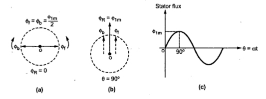
Fig 2. Double revolving field theory
Key takeaways:
1. The net torque in the motor is equal to the sum of the torque due to each of the two magnetic fields.
2. At the standstill condition, the induced voltages are equal and opposite as a result; the two torques are also equal and opposite.
1. The equivalent circuit of any machine shows the various parameter of the machine such as its Ohmic losses and also other losses.
2. The losses are modeled just by inductor and resistor.
3. The copper losses have occurred in the windings so the winding resistance is taken into account. Also, the winding has inductance for which there is a voltage drop due to inductive reactance, and also a term called power factor comes into the picture. There are two types of equivalent circuits in the case of a three-phase induction motor-
Exact Equivalent Circuit
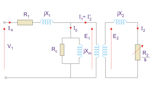
Fig 3. Equivalent Circuit
Here, R1 is the winding resistance of the stator.
X1 is the inductance of the stator winding.
Rc is the core loss component.
XM is the magnetizing reactance of the winding.
R2/s is the power of the rotor, which includes output mechanical power and copper loss of the rotor.
If we draw the circuit with referred to the stator then the circuit will look like-
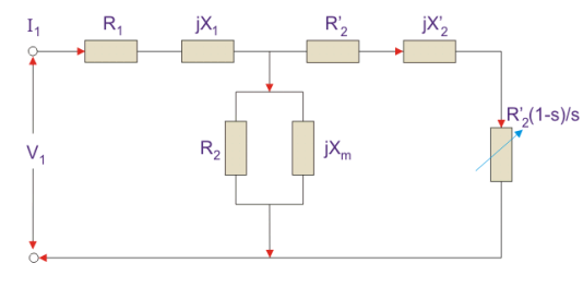
Fig 4. Equivalent circuit
Here all the other parameters are the same except-
R2’ is the rotor winding resistance referred to as stator winding.
X2’ is the rotor winding inductance referred to as stator winding.
R2 (1 – s) / s is the resistance that shows the power which is converted to mechanical power output or useful power. The power dissipated in that resistor is the useful power output or shaft power.
4. The approximate equivalent circuit is drawn just to simplify our calculation by deleting one node. The shunt branch is shifted towards the primary side.
5. This has been done as the voltage drop between the stator resistance and inductance is less and there is not much difference between the supply voltage and the induced voltage.
However, this is not appropriate due to the following reasons-
1. The magnetic circuit of the induction motor has an air gap so the exciting current is larger compared to the transformer so an exact equivalent circuit should be used.
2. The rotor and stator inductance is larger in the induction motor.
3. In an induction motor, we use distributed windings.
4. This model can be used if the approximate analysis has to be done for large motors. For smaller motors, we cannot use this.
Key takeaways:
1. The winding has inductance for which there is a voltage drop due to inductive reactance and also a term called power factor comes into the picture.
2. This has been done as the voltage drop between the stator resistance and inductance is less and there is not much difference between the supply voltage and the induced voltage.
3. The magnetic circuit of the induction motor has an air gap so the exciting current is larger compared to the transformer so an exact equivalent circuit should be used.
1. A stationary pulsating magnetic field might be resolved into two rotating fields, both having equal magnitude but opposite in direction.
2. So the net torque induced is zero at standstill. Here, the forward rotation is called the rotation with slip s, and the backward rotation is given with a slip of (2 – s). The equivalent circuit is-
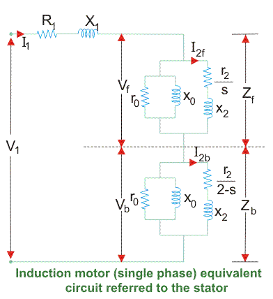
Fig 5. Equivalent circuit
3. In most cases the core loss component r0 is neglected as this value is quite large and does not affect much in the calculation.
4. Here, Zf shows the forward impedance and Zb shows the backward impedance.
Also, the sum of forwarding and backward slip is 2 so in case of a backward slip, it is replaced by (2 – s).
R1 = Resistance of the stator winding.
X1 = Inductive reactance of the stator winding.
Xm = Magnetising reactance.
R2’ = Rotor Reactance with referred to the stator.
X2’ = Rotor inductive reactance with referred to the stator.
Key takeaways:
1. A stationary pulsating magnetic field might be resolved into two rotating fields, both having equal magnitude but opposite in direction
2. The net torque induced is zero at a standstill
1. The Split Phase Motor is also known as a Resistance Start Motor. It has a single cage rotor, and its stator has two windings known as main winding and starting winding.
2. Both the windings are displaced 90 degrees in space. The main winding has very low resistance and a high inductive reactance whereas the starting winding has high resistance and low inductive reactance.
3. Split-Phase-Induction-Motor-resistor is connected in series with the auxiliary winding. The current in the two windings is not equal as a result the rotating field is not uniform.
4. Hence, the starting torque is small, of the order of 1.5 to 2 times of the starting running torque. At the starting of the motor both the windings are connected in parallel.
5. As soon as the motor reaches the speed of about 70 to 80 % of the synchronous speed the starting winding is disconnected automatically from the supply mains.
6. If the motors are rated about 100 Watt or more, a centrifugal switch is used to disconnect the starting winding and for the smaller rating motors relay is used for the disconnecting of the winding.
7. A relay is connected in series with the main winding. In the starting, the heavy current flows in the circuit, and the contact of the relay gets closed.
8. Thus, the starting winding is in the circuit, and as the motor attains the predetermined speed, the current in the relay starts decreasing. Therefore, the relay opens and disconnects the auxiliary winding from the supply, making the motor runs on the main winding only.
The phasor diagram of the Split Phase Induction Motor is shown below.
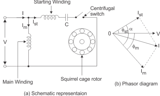
Fig 6. Schematic diagram and phasor diagram of split-phase induction motor
9. Split-Phase-Induction-Motor-The current in the main winding (IM) lag behind the supply voltage V almost by the 90-degree angle. The current in the auxiliary winding IA is approximately in phase with the line voltage.
10. Thus, there exists a time difference between the currents of the two windings. The time phase difference ϕ is not 90 degrees, but of the order of 30 degrees. This phase difference is enough to produce a rotating magnetic field.
Applications of Split Phase Induction Motor
This type of motors are cheap and are suitable for easily starting loads where the frequency of starting is limited. This type of motor is not used for drives that require more than 1 KW because of the low starting torque. The various applications are as follows:-
1. Used in the washing machine, and air conditioning fans.
2. The motors are used in mixer grinder, floor polishers.
3. Blowers, Centrifugal pumps
4. Drilling and lathe machine.
Key takeaways:
1. As soon as the motor reaches the speed of about 70 to 80 % of the synchronous speed the starting winding is disconnected automatically from the supply mains.
2. This type of motor is not used for drives that require more than 1 KW because of the low starting torque
4.7.1. Permanent split capacitor method [psc]
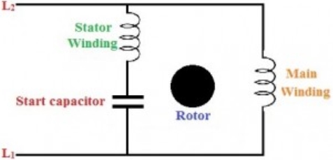
Fig 7. Permanent split capacitor method [psc]
1. In a capacitor start method, a capacitor has to be disconnected after the motor reaches a specific speed of the motor.
2. But in this method, a run-type capacitor is placed in series with the start winding or auxiliary winding. This capacitor is used continuously, and it doesn’t require any switch to disconnect it as it is not used to start the motor only.
3.The starting torque of the PSC is similar to the spilt-phase motors, but with a low starting current.
4.7.2 Capacitor start and capacitor run
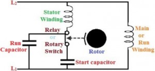
Fig 8. Capacitor Start Capacitor Run
1. The features of the capacitor start and PSC methods can be combined with this method.
2. Run capacitor is connected in series with the start winding or auxiliary winding, and a start capacitor is connected in the circuit using a normally closed switch while starting the motor.
3. Start capacitor provides starting boost to the motor and PSC provides a high running to the motor. It is more costly but still facilitates high starting and breakdown torque along with smooth running characteristics at high horsepower ratings.
Key takeaways:
1. This capacitor is used continuously, and it doesn’t require any switch to disconnect it as it is not used to start the motor only.
2. Start capacitor provides starting boost to the motor and PSC provides a high running to the motor.
Input power to stator- 3 V1I1Cos(Ɵ).
Where V1 is the stator voltage applied.
I1 is the current drawn by the stator winding.
Cos(Ɵ) is the stator power stator.
Rotor input =
Power input- Stator copper and iron losses.
Rotor Copper loss = Slip × power input to the rotor.
Developed Power = (1 – s) × Rotor input power.
Equivalent Circuit of a Single-Phase Induction Motor
1. There is a difference between single-phase and three-phase equivalent circuits. The single-phase induction motor circuit is given by double-revolving field theory which states that-a stationary pulsating magnetic field might be resolved into two rotating fields, both having equal magnitude but opposite in direction.
2. So the net torque induced is zero at standstill. Here, the forward rotation is called the rotation with slip s, and the backward rotation is given with a slip of (2 – s). The equivalent circuit is-
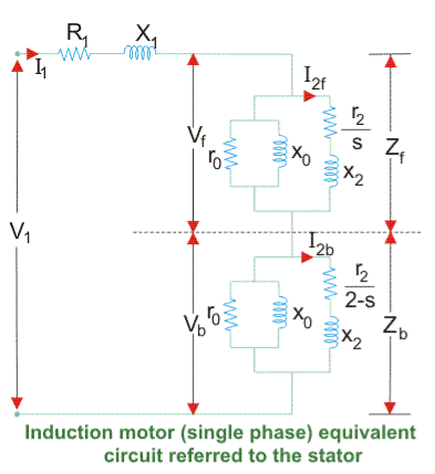
Fig 9. Development of equivalent circuit
3. Equivalent circuit of a single-phase induction motor
In most cases, the core loss component r0 is neglected as this value is quite large and does not affect much in the calculation.
Here, Zf shows the forward impedance and Zb shows the backward impedance.
Also, the sum of forwarding and backward slip is 2 so in the case of a backward slip, it is replaced by (2 – s).
R1 = Resistance of the stator winding.
X1 = Inductive reactance of the stator winding.
Xm = Magnetising reactance.
R2’ = Rotor Reactance with referred to the stator.
X2’ = Rotor inductive reactance with referred to the stator.
4. Calculation of Power of Equivalent Circuit
Find Zf and Zb.
Find stator current which is given by Stator voltage/Total circuit impedance.
Then find the input power which is given by
Stator voltage × Stator current × Cos(Ɵ)
Where Ɵ is the angle between the stator current and voltage.
Power Developed (Pg) is the difference between forwarding field power and backward power. The forward and backward power is given by the power dissipated in the respective resistors.
The rotor copper loss is given by- slip × Pg.
Output Power is given by-
Pg – s × Pg – Rotational loss.
The rotational losses include friction loss, windage loss, Core loss.
Efficiency can also be calculated by diving output power by the input power.
Key takeaways:
1. Power Developed (Pg) is the difference between forwarding field power and backward power. The forward and backward power is given by the power dissipated in the respective resistors.
2. The forward rotation is called the rotation with slip s and the backward rotation is given with a slip of (2 – s)
1.8.1 Blocked rotor test
1. The induction motors are widely used in industries and consume maximum power. To improve its performance characteristics certain tests have been designed like no-load test and block rotor test, etc.
2. A blocked rotor test is normally performed on an induction motor to find out the leakage impedance.
3. Apart from it, other parameters such as torque, motor, short-circuit current at normal voltage, and many more could be found from this test. The blocked rotor test is analogous to the short circuit test of the transformer.
4. Here shaft of the motor is clamped i.e. blocked so it cannot move and rotor winding is short-circuited.
5.In slip ring motor rotor winding is short-circuited through slip rings and in cage motors, rotor bars are permanently short-circuited.
6. The testing of the induction motor is a little bit complex as the resultant value of leakage impedance may get affected by rotor position, rotor frequency, and magnetic dispersion of the leakage flux path.
7.These effects could be minimized by conducting a blocking rotor current test on squirrel-cage rotors.
Process of Testing of Blocked Rotor Test of Induction Motor
1. In the blocked rotor test, it should be kept in mind that the applied voltage on the stator terminals should be low otherwise normal voltage could damage the winding of the stator.
2. In the block rotor test, the low voltage is applied so that the rotor does not rotate and its speed becomes zero and full load current passes through the stator winding.
3. The slip is unity related to zero speed of rotor hence the load resistance becomes zero. Now, slowly increase the voltage in the stator winding so that the current reaches its rated value.
4. At this point, note down the readings of the voltmeter, wattmeter, and ammeter to know the values of voltage, power, and current. The test can be repeated at different stator voltages for the accurate value.
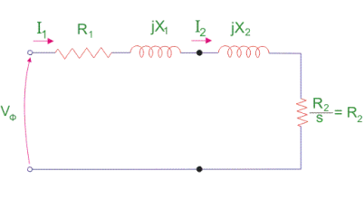
Fig 10. Block rotor test
5. Calculations of Blocked Rotor Test of Induction Motor
Resistance and Leakage Reactance Values
In blocked rotor test, core loss is very low due to the supply of low voltage and frictional loss is also negligible as the rotor is stationary, but stator copper losses and the rotor copper losses are reasonably high.
Let us take denote copper loss by Wcu.
Calculations of Blocked Rotor Test of Induction Motor
Resistance and Leakage Reactance Values
In blocked rotor test, core loss is very low due to the supply of low voltage and frictional loss is also negligible as the rotor is stationary, but stator copper losses and the rotor copper losses are reasonably high.
Let us take denote copper loss by Wcu.
Therefore,

Where Wc = core loss

Where R01 = Motor winding of stator and rotor as per phase referred to the stator.
Thus,

Now let us consider
Is = short circuit current
Vs = short circuit voltage
Z0 = short circuit impedance as referred to stator
Therefore,

X01 = Motor leakage reactance per phase referred to stator can be calculated as
Stator reactance X1 and rotor reactance per phase referred to as stator X2 is normally assumed equal.
Therefore,


Similarly, stator resistance per phase R1 and rotor resistance per phase referred to stator R2 can be calculated as follows:
First, some suitable test is done on stator windings to find the value of R1 and then to find R2 subtract the R1 from R01

Short Circuit Current for Normal Supply Voltage
To calculate short circuit current Isc at normal voltage V of the stator, we must note short-circuit current Is and low voltage Vs applied to the stator winding.

Key takeaways:
1. In the blocked rotor test, it should be kept in mind that the applied voltage on the stator terminals should be low otherwise normal voltage could damage the winding of the stator.
2. The testing of the induction motor is a little bit complex as the resultant value of leakage impedance may get affected by rotor position, rotor frequency, and magnetic dispersion of the leakage flux path.
3. To calculate short circuit current Isc at normal voltage V of the stator, we must note short-circuit current Is and low voltage Vs applied to the stator winding.
4.8.2 No-load test
1. The impedance of magnetizing path of the induction motor is large enough to obstruct the flow of current. Therefore, a small current is applied to the machine due to which there is a fall in the stator-impedance value, and rated voltage is applied across the magnetizing branch.
2. But the drop in stator-impedance value and power dissipated due to stator resistance is very small in comparison to the applied voltage. Therefore, their values are neglected and it is assumed that total power drawn is converted into core loss.
3. The air gap in a magnetizing branch in an induction motor slowly increases the exciting current and the no-load stator I2R loss can be recognized.
4. One should keep in mind that the current should not exceed its rated value otherwise rotor accelerates beyond its limit.
5. The test is performed at poly-phase voltages and rated frequency applied to the stator terminals. When the motor runs for some time and bearings get lubricated fully, at that time readings of applied voltage, input current, and input power are taken.
6. To calculate the rotational loss, subtract the stator I2R losses from the input power.
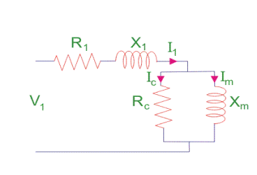
Fig 11. No-load test
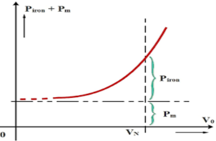
Fig 12. Graph for no-load test
Calculation of No-Load Test of Induction Motor
Let the total input power supplied to the induction motor be W0 watts.
Where,
V1 = line voltage
I0 = No-load input current
Rotational loss = W0 – S1
Where,
 …….(1)
S1 = stator winding loss = Nph I2 R1
Nph = Number phase
The various losses like windage loss, core loss, and rotational loss are fixed losses that can be calculated by
Stator winding loss = 3Io2R1
Where,
I0 = No load input current
R1 = Resistance of the motor
Core loss = 3GoV2
Key takeaways:
1. The impedance of magnetizing path of induction motor is large enough to obstruct the flow of current
2. One should keep in mind that the current should not exceed its rated value otherwise rotor accelerates beyond its limit.
References :
1. A. E. Fitzgerald and C. Kingsley, "Electric Machinery”, McGraw Hill Education,2013.
2. M. G. Say, “Performance and design of AC machines”, CBS Publishers,2002.
3. P. S. Bimbhra, “Electrical Machinery”, Khanna Publishers,2011.
4. I. J. Nagrath and D. P. Kothari, “Electric Machines”, McGraw Hill Education,2010.
5. A. S. Langsdorf, “Alternating current machines”, McGraw Hill Education,1984.
6. P. C. Sen, “Principles of Electric Machines and Power Electronics”, John Wiley & Sons,2007.
Unit - 2
Context-free languages and pushdown automata
Context-free grammar (CFG) is a collection of rules (or productions) for recursive rewriting used to produce string patterns.
It consists of:
● a set of terminal symbols,
● a set of non-terminal symbols,
● a set of productions,
● a start symbol.
Context-free grammar G can be defined as:
G = (V, T, P, S)
Where
G - grammar, used for generate string,
V - final set of non-terminal symbol, which are denoted by capital letters,
T - final set of terminal symbols, which are denoted be small letters,
P - set of production rules, it is used for replacing non terminal symbol of a string in both side (left or right)
S - start symbol, which is used for derive the string
A CFG for Arithmetic Expressions -
An example grammar that generates strings representing arithmetic expressions with the four operators +, -, *, /, and numbers as operands is:
1. <expression> --> number
2. <expression> --> (<expression>)
3.<expression> --> <expression> +<expression>
4. <expression> --> <expression> - <expression>
5. <expression> --> <expression> * <expression>
6. <expression> --> <expression> / <expression>
The only non-terminal symbol in this grammar is <expression>, which is also the
Start symbol. The terminal symbols are {+, -, *, /, (,), number}
● The first rule states that an <expression> can be rewritten as a number.
● The second rule says that an <expression> enclosed in parentheses is also an <expression>
● The remaining rules say that the sum, difference, product, or division of two <expression> is also an expression.
Context free language (CFL)
A context-free language (CFL) is a language developed by context-free grammar (CFG) in formal language theory. In programming languages, context-free languages have many applications, particularly most arithmetic expressions are created by context-free grammars.
● Through comparing different grammars that characterize the language, intrinsic properties of the language can be separated from extrinsic properties of a particular grammar.
● In the parsing stage, CFLs are used by the compiler as they describe the syntax of a programming language and are used by several editors.
A grammatical description of a language has four essential components -
- There is a set of symbols that form the strings of the language being defined. They are called terminal symbols, represented by V t.
- There is a finite set of variables, called non-terminals. These are represented by V n .
- One of the variables represents the language being defined; it is called the start symbol. It is represented by S.
- There are a finite set of rules called productions that represent the recursive definition of a language. Each production consists of:
● A variable that is being defined by the production. This variable is also called the production head.
● The production symbol ->
● A string of zero terminals and variables, or more.
Key takeaway:
- CFG is a collection of rules (or productions) for recursive rewriting used to produce string patterns.
- CFL is a language developed by context-free grammar (CFG) in formal language theory.
Chomsky normal forms
A context free grammar (CFG) is in Chomsky Normal Form (CNF) if all production
Rules satisfy one of the following conditions:
A non-terminal generating a terminal (e.g.; X->x)
A non-terminal generating two non-terminals (e.g.; X->YZ)
Start symbol generating ε. (e.g.; S->ε)
Consider the following grammars,
G1 = {S->a, S->AZ, A->a, Z->z}
G2 = {S->a, S->aZ, Z->a}
The grammar G1 is in CNF as production rules satisfy the rules specified for
CNF. However, the grammar G2 is not in CNF as the production rule S->aZ contains
Terminal followed by non-terminal which does not satisfy the rules specified for CNF.
Key takeaway:
- CNF is a pre-processing step used in various algorithms.
- For generation of string x of length ‘m’, it requires ‘2m-1’ production or steps in CNF.
Greibach normal forms
A CFG is in Greibach Normal Form if the Productions are in the following forms −
A → b
A → bD 1 …D n
S → ε
Where A, D 1 ,...., D n are non-terminals and b is a terminal.
Algorithm to Convert a CFG into Greibach Normal Form
Step 1 − If the start symbol S occurs on some right side, create a new start
Symbol S’ and a new production S’ → S.
Step 2 − Remove Null productions.
Step 3 − Remove unit productions.
Step 4 − Remove all direct and indirect left-recursion.
Step 5 − Do proper substitutions of productions to convert it into the proper form of
GNF.
Problem
Convert the following CFG into CNF
S → XY | Xn | p
X → mX | m
Y → Xn | o
Solution
Here, S does not appear on the right side of any production and there are no unit or
Null productions in the production rule set. So, we can skip Step 1 to Step 3.
Step 4
Now after replacing
X in S → XY | Xo | p
With
MX | m
We obtain
S → mXY | mY | mXo | mo | p.
And after replacing
X in Y → X n | o
With the right side of
X → mX | m
We obtain
Y → mXn | mn | o.
Two new productions O → o and P → p are added to the production set and then
We came to the final GNF as the following −
S → mXY | mY | mXC | mC | p
X → mX | m
Y → mXD | mD | o
O → o
P → p
The non-deterministic pushdown automata is very much similar to NFA. We will
Discuss some CFGs which accept NPDA.
The CFG which accepts deterministic PDA accepts non-deterministic PDAs as well.
Similarly, there are some CFGs which can be accepted only by NPDA and not by
DPDA. Thus NPDA is more powerful than DPDA.
Example:
Design PDA for Palindrome strips.
Solution:
Suppose the language consists of string L = {aba, aa, bb, bab, bbabb, aabaa, ......].
The string can be odd palindrome or even palindrome. The logic for constructing
PDA is that we will push a symbol onto the stack till half of the string then we will
Read each symbol and then perform the pop operation. We will compare to see
Whether the symbol which is popped is similar to the symbol which is read. Whether
We reach the end of the input, we expect the stack to be empty.
This PDA is a non-deterministic PDA because finding the mid for the given string and
Reading the string from left and matching it with from right (reverse) direction leads to non-deterministic moves.
Here is the ID.
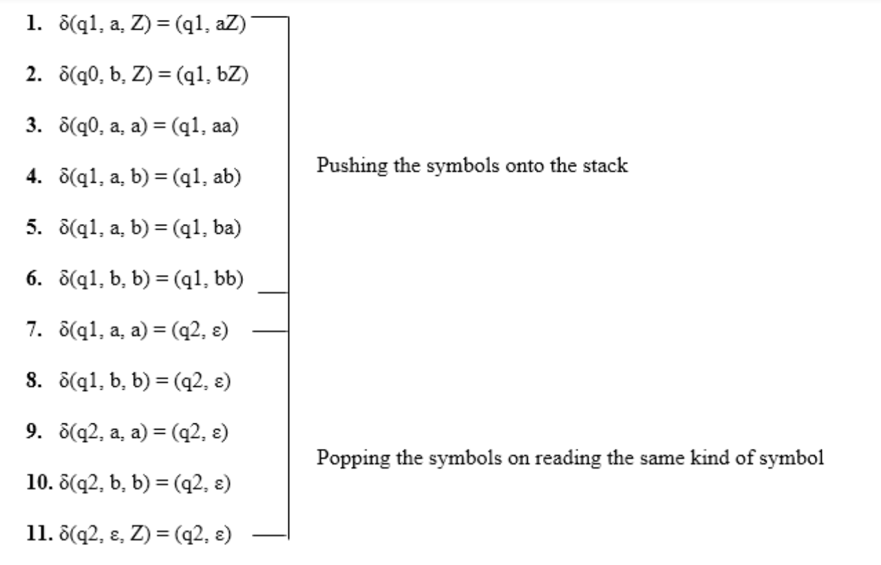
Simulation of abaaba
1. δ(q1, abaaba, Z) Apply rule 1
2. δ(q1, baaba, aZ) Apply rule 5
3. δ(q1, aaba, baZ) Apply rule 4
4. δ(q1, aba, abaZ) Apply rule 7
5. δ(q2, ba, baZ) Apply rule 8
6. δ(q2, a, aZ) Apply rule 7
7. δ(q2, ε, Z) Apply rule 11
8. δ(q2, ε) Accept
● A parse tree is an entity which represents the structure of the derivation of a
Terminal string from some non-terminal.
● The graphical representation of symbols is the Parse tree. Terminal or non-terminal may be the symbol.
● In parsing, using the start symbol, the string is derived. The starter symbol is the root of the parse tree.
● It is the symbol's graphical representation, which can be terminals or non-terminals.
● The parse tree follows operators' precedence. The deepest sub-tree went through first. So, the operator has less precedence over the operator in the sub-tree in the parent node.
Key features to define are the root ∈ V and yield ∈ Σ * of each tree.
● For each σ ∈ Σ, there is a tree with root σ and no children; its yield is σ
● For each rule A → ε, there is a tree with root A and one child ε; its yield is ε
● If t 1 , t 2 , ..., t n are parse trees with roots r 1 , r 2 , ..., r n and respective yields y 1 , y 2 ,..., y n , and A → r 1 r 2 ...r n is a production, then there is a parse tree with root A whose children are t 1 , t 2 , ..., t n . Its root is A and its yield is the concatenation of yields: y 1 y 2 ...y n
Here, parse trees are constructed from bottom up, not top down.
The actual construction of “adding children” should be made more precise, but we intuitively know what’s going on.
As an example, here are all the parse (sub) trees used to build the parse tree
For the arithmetic expression 4 + 2 * 3 using the expression grammar
E → E + T | E - T | T
T → T * F | F
F → a | ( E )
Where a represents an operand of some type, be it a number or variable. The
Trees are grouped by height.
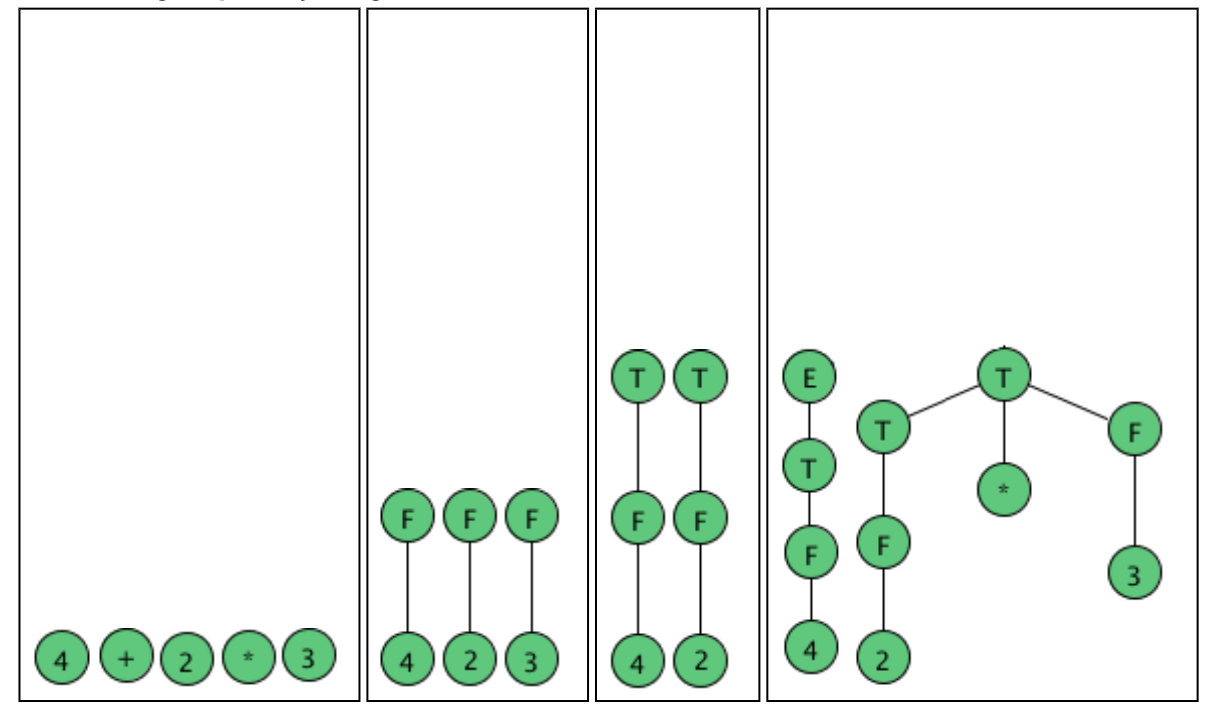
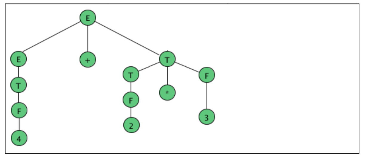
Fig 1: example of parse tree
Parse Trees and Derivations
A derivation is a sequence of strings in V * which starts with a non-terminal
In V-Σ and ends with a string in Σ * .
Let’s consider the sample grammar
E → E+E | a
We write:
E ⇒ E+E ⇒ E+E+E ⇒a+E+E⇒a+a+E⇒a+a+a
But this is incomplete, because it doesn’t tell us where the replacement rules are
Applied.
We actually need "marked" strings which indicate which non-terminal is replaced in all but the first and last step:
E ⇒ Ě+E ⇒ Ě+E+E ⇒a+Ě+E ⇒a+a+Ě ⇒a+a+a
In this case, the marking is only necessary in the second step; however it is crucial,
Because we want to distinguish between this derivation and the following one:
E ⇒ E+Ě ⇒ Ě+E+E ⇒a+Ě+E ⇒a+a+Ě ⇒a+a+a
We want to characterize two derivations as “coming from the same parse tree.”
The first step is to define the relation among derivations as being “more left-oriented at one step”. Assume we have two equal length derivations of length n > 2:
D: x 1 ⇒ x 2 ⇒ ... ⇒x n
D′: x 1 ′ ⇒ x 2 ′ ⇒ ... ⇒x n ′
Where x 1 = x 1 ′ is a non-terminal and
x n = x n ′ ∈ Σ *
Namely they start with the same non-terminal and end at the same terminal string
And have at least two intermediate steps.
Let’s say D < D′ if the two derivations differ in only one step in which there are 2 non-
Terminals, A and B, such that D replaces the left one before the right one and D′ does the opposite. Formally:
D < D′ if there exists k, 1 < k < n such that
x i = x i ′ for all i ≠ k (equal strings, same marked position)
x k-1 = uǍvBw, for u, v, w ∈ V*
x k-1 ′ = uAvB̌w, for u, v, w ∈ V*
x k =uyvB̌w, for production A → y
x k ′ = uǍvzw, for production B → z
x k+1 = x k+1 ′ = uyvzw (marking not shown)
Two derivations are said to be similar if they belong to the reflexive, symmetric, transitive closure of <.
Key takeaway:
- In parsing, using the start symbol, the string is derived. The starter symbol is the root of the parse tree.
- The graphical representation of symbols is the Parse tree. Terminal or non-terminal may be the symbol.
Suppose we have a context free grammar G with production rules:
S->aSb|bSa|SS|ɛ
Left most derivation (LMD) and Derivation Tree:
Leftmost derivation of a string from staring symbol S is done by replacing leftmost
Non-terminal symbol by RHS of corresponding production rule.
For example:
The leftmost derivation of string abab from grammar G above is done as:
S =>aSb =>abSab =>abab
The symbols in bold are replaced using production rules.
Derivation tree: It explains how string is derived using production rules from S and
Is shown in Figure.
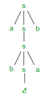
Fig 2: derivation tree
Right most derivation (RMD):
It is done by replacing rightmost non-terminal symbol S by RHS of corresponding production rule.
For Example: The rightmost derivation of string abab from grammar G above
Is done as:
S =>SS =>SaSb =>Sab =>aSbab =>abab
The symbols in bold are replaced using production rules.
The derivation tree for abab using rightmost derivation is shown in Figure.
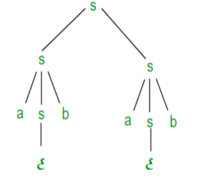
Fig 3: right most derivation
A derivation can be either LMD or RMD or both or none.
For Example:
S =>aSb =>abSab =>abab is LMD as well as RMD But
S => SS =>SaSb =>Sab =>aSbab =>abab is RMD but not LMD.
Ambiguous Context Free Grammar:
● A context free grammar is called ambiguous if there exists more than one
LMD or RMD for a string which is generated by grammar.
● There will also be more than one derivation tree for a string in ambiguous grammar.
● The grammar described above is ambiguous because there are two derivation
Trees.
● There can be more than one RMD for string abab which are:
S =>SS =>SaSb =>Sab =>aSbab =>abab
S =>aSb =>abSab =>abab
Key takeaway:
- If there is uncertainty in the grammar, then it is not good for the construction of compilers.
- No method can detect and eliminate ambiguity automatically, but by re-writing the entire grammar without ambiguity, we can remove ambiguity.
Lemma: The language L = {anbncn | n ≥ 1} is not context free.
Proof (By contradiction)
Assuming that this language is context-free; hence it will have a context-free
Grammar.
Let K be the constant of the Pumping Lemma.
Considering the string akbkck , where L is length greater than K .
By the Pumping Lemma this is represented as uvxyz , such that all uvixyiz are also
In L, which is not possible, as:
Either v or y cannot contain many letters from {a,b,c}; else they are in the wrong
Order .
If v or y consists of a’s, b’s or c’s, then uv2xy2z cannot maintain the balance
Amongst the three letters.
Lemma: The language L = {aibjck | i < j and i < k} is not context free.
Proof (By contradiction)
Assuming that this language is context-free; hence it will have a context-free grammar.
Let K be the constant of the Pumping Lemma.
Considering the string akbk+1ck+1, which is L > K.
By the Pumping Lemma this must be represented as uvxyz, such that all are also
In L.
-As mentioned previously neither v nor y may contain a mixture of symbols.
-Suppose consists of a’s.
Then there is no way y cannot have b’s and c’s. It generates enough letters to keep
Them more than that of the a’s (it can do it for one or the other of them, not both)
Similarly, y cannot consist of just a’s.
-So, suppose then that v or y contains only b’s or only c’s.
Consider the string uv0xy0z which must be in L . Since we have dropped both
v and y, we must have at least one b’ or one c’ less than we had in uvxyz , which
Was akbk+1ck+1. Consequently, this string no longer has enough of either b’s or
c’s to be a member of L .
- Machine transitions are based on the current state and input symbol, and also
The current topmost symbol of the stack.
- Symbols lower in the stack are not visible and have no immediate effect.
- Machine actions include pushing, popping, or replacing the stack top.
- A deterministic pushdown automaton has at most one legal transition for the
Same combination of input symbol, state, and top stack symbol.
- This is where it differs from the nondeterministic pushdown automaton.
- DPDA is a subset of context free language
A deterministic pushdown automata M can be defined as 7 tuples -
M = (Q, ∑, T, q0, Z0, A, δ)
Where,
● Q is finite set of states,
● ∑ is finite set of input symbol,
● T is a finite set of stack symbol,
● q0 ∈ Q is a start state,
● Z0 ∈ T is the starting stack symbol,
● A ⊆ Q, where A is a set of accepting states,
● δ is a transition function, where :
δ :(Q X ( ∑ U {ε }) X T ) ➝ p(Q X T* )
Key takeaway:
- DPDA is a subset of context free language.
- Machine transitions are based on the current state and input symbol, and also
The current topmost symbol of the stack.
They are closed under −
● Union
● Concatenation
● Kleene Star operation
Union of the languages A1 and A2 , A = A1 A2 = { anbncmdm }
The additional development would have the corresponding grammar G, P: S → S1 S2
Union
Let A1 and A2 be two context free languages. Then A1 ∪ A2 is also context free.
Example
Let A1 = { xn yn , n ≥ 0}. Corresponding grammar G 1 will have P: S1 → aAb|ab
Let A2 = { cm dm , m ≥ 0}. Corresponding grammar G 2 will have P: S2 → cBb| ε
Union of A1 and A2 , A = A1 ∪ A2 = { xn yn } ∪ { cm dm }
The corresponding grammar G will have the additional production S → S1 | S2
Note - So under Union, CFLs are closed.
Concatenation
If A1 and A2 are context free languages, then A1 A2 is also context free.
Example
Union of the languages A 1 and A 2 , A = A 1 A 2 = { an bn cm dm }
The corresponding grammar G will have the additional production S → S1 S2
Note - So under Concatenation, CFL are locked .
Kleene Star
If A is a context free language, so that A* is context free as well .
Example
Let A = { xn yn , n ≥ 0}. G will have corresponding grammar P: S → aAb| ε
Kleene Star L 1 = { xn yn }*
The corresponding grammar G 1 will have additional productions S1 → SS 1 | ε
Note - So under Kleene Closure, CFL's are closed .
Context-free languages are not closed under −
● Intersection − If A1 and A2 are context free languages, then A1 ∩ A2 is not necessarily context free.
● Intersection with Regular Language − If A1 is a regular language and A2 is a context free language, then A1 ∩ A2 is a context free language.
● Complement − If A1 is a context free language, then A1’ may not be context free.
References:
- John E. Hopcroft, Rajeev Motwani and Jeffrey D. Ullman, Introduction to
Automata Theory, Languages, and Computation, Pearson Education Asia.
2. Dexter C. Kozen, Automata and Computability, Undergraduate Texts in
Computer Science, Springer.
3. Michael Sipser, Introduction to the Theory of Computation, PWS Publishing.