Unit 5
Special machines
Q1. Explain construction and working of hysteresis motor?
Ans:
Hysteresis Motor Construction
A hysteresis motor is constructed of five main components:
1. Stator
2. Single phase stator winding
3. Rotor
4. Shaft
5. Shading coil
The two most important components of the hysteresis motor are the stator and rotor:
1. Stator: Stator of hysteresis motor is designed in a particular manner to produce synchronous revolving field from single phase supply. Stator carries two windings, (a) main winding (b) auxiliary winding. In another type of design of hysteresis motor the stator holds the poles of shaded type.
2. Rotor: Rotor of hysteresis motor is made of magnetic material that has high hysteresis loss property. Example of this type of materials is chrome, cobalt steel or alnico or alloy. Hysteresis loss becomes high due to large area of hysteresis loop.
3. Rotor does not carry any winding or teeth. The magnetic cylindrical portion of the rotor is assembled over shaft through arbor of nonmagnetic material like brass.
4. Rotor is provided with high resistance to reduce eddy current loss.
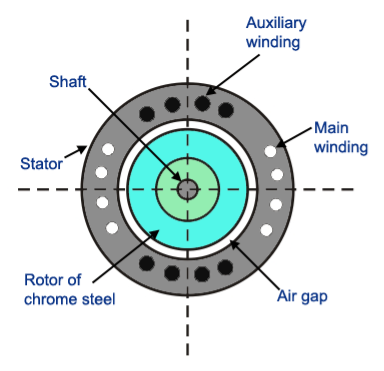
Fig : Hysteresis motor
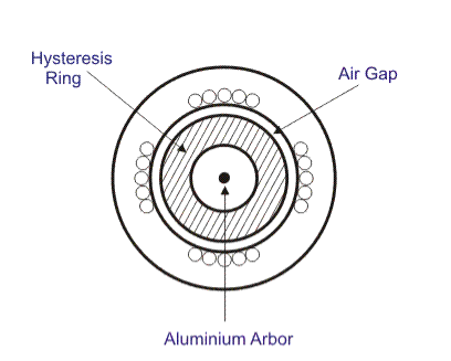
Fig : external part of hysteresis motor
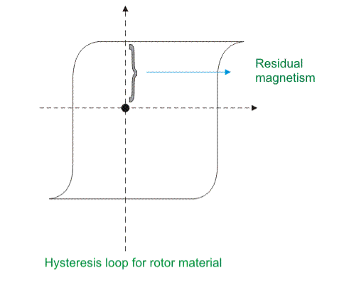
Fig : graph for hysteresis motor
Working Principle of Hysteresis Motor
Starting behaviour of a hysteresis motor is like a single phase induction motor and running behaviour is same as a synchronous motor. Step by step its behavior can be realized in the working principle that is given below.
A. At the Starting Condition
1. When stator is energized with single phase AC supply, rotating magnetic field is produced in stator.
2. To maintain the rotating magnetic field the main and auxiliary windings must be supplied continuously at start as well as in running conditions.
3. At the starting, by induction phenomenon, secondary voltage is induced in the rotor by stator rotating magnetic field. Hence eddy current is generated to flow in the rotor and it develops rotor.
4. Thus eddy current torque is developed along with the hysteresis torque in the rotor. Hysteresis torque in the rotor develops as the rotor magnetic material is with high hysteresis loss property and high retentively.
5. The rotor goes under the slip frequency before going to the steady state running condition.
6. So it can be said that when the rotor starts to rotate with the help of these eddy current torque due to induction phenomenon, it behalves like a single phase induction motor.
B. At Steady State Running Condition
1. When the speed of the rotor reaches near about the synchronous speed, the stator pulls the rotor into synchronism.
2. At the condition of synchronism, the relative motion between stator field and rotor field vanishes. So there is no further induction phenomenon to continue. Hence no eddy current to generate in the rotor. Thus the torque due to eddy-currents vanishes.
3. At the time of rotor’s rotation at the synchronous speed, rotating magnetic field flux in the stator produces poles on the rotor by induction; they are named as north (N) and south (S) poles. Thus rotor behaves as a permanent magnet having rotor axis as the induced magnetic axis.
4. For high residual magnetism or retentivity the rotor pole strength remains sustainable or unchanged. Again higher the retentivity, higher is the hysteresis torque and the hysteresis torque is independent of the rotor speed always. The high retentivity enables the continuous magnetic locking between stator and rotor and thus the motor rotates at synchronous speed.
5. The maximum work done to establish the hysteresis losses under the magnetization cycle in the rotor is equal to the surface area inside B-H hysteresis curve.
6. In lower load torque, the needed work done to rotate the rotor is equal to maximum magnetizing work of hysteresis phenomenon available already in the rotor. So induced magnetic pole axis always follows the rotating magnetic field axis of stator without any lag angle.
7. But when the load torque is sufficiently high, the maximum magnetizing work in rotor by hysteresis phenomenon cannot fulfill the work done needed to rotate the rotor.
8. So the induced magnetic field axis or rotor pole axis lags the rotating magnetic field axis of the stator at an angle δh. Hence the rotor pole axis tries to catch up the stator magnetic field axis.
9. If the load torque is increased, this lagging angle will be increased up to δmax before dropping below the synchronous condition.
10. The rotor poles are attracted towards the moving stator poles and runs at synchronous speed.
Q2. Explain construction and working of Switched reluctance motor ?
Ans:
Construction of Switched Reluctance Motor
Variable Reluctance Motor or Switched Reluctance Motor has two different constructions: Singly Salient Construction and Doubly Salient Construction. Stator and rotor magnetic circuits are laminated to reduce the core losses in both type of SRM.
A: Singly Salient Construction:
1. A singly salient construction SRM comprises of a non-salient stator and a salient two pole rotor.
2.The rotor do not have any winding wound over it but the stator have two phase winding as shown in figure below.
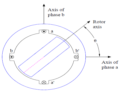
Fig : switched reluctance motor
3. It should be noted that, in actual SRM the number of phase winding on stator may be more than two. Since the rotor is of salient construction, the inductance of stator phase winding varies with the rotor position.
4. The inductance is minimum when the rotor axis and stator phase winding axis coincides whereas it is maximum when both the axis are in quadrature.
B: Doubly Salient Construction:
1. Unlike singly salient type, the stator of doubly salient Switched Reluctance Motor is of salient construction and consists of four poles as shown in figure below.
2.The rotor do not carry any winding and is of salient construction but have two poles. Thus this type of SRM is a hetropolar motor where the numbers of stator and rotor poles are not same.
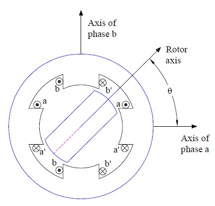
Fig : Double salient construction
3. The stator phase windings are concentrated winding. These concentrated windings on radially opposite poles are either connected in series or parallel to result into two phase winding on stator.
4. A doubly salient type Switched Reluctance Motor or variable Reluctance Motor produces more torque as compared to singly salient type for the same size. Therefore a doubly SRM is more common and widely used.
Working principle of Switched Reluctance Motor (SRM)
1. As we know that magnetic flux have a tendency to flow through lowest reluctance path, therefore rotor always tends to align along the minimum reluctance path. This is the basic working principle of Switched Reluctance Motor or Variable Reluctance Motor.
2. Thus rotor rotation in clockwise direction is achieved by energizing the phase winding in a ABC sequence. If rotor rotation in anti-clockwise direction is require, stator phase winding must be energized in ACB sequence.
3. It must also be noted that, a particular phase winding must be energized / de-energized in synchronism with rotor position. This means as soon as the rotor align along the A phase, B phase must be energized and A phase must be de-energized if clockwise rotor rotation is required.
To better understand the working principle, carefully observe the animation of Switched Reluctance Motor given below.
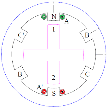
Fig : working diagram
Q3.explain Stepper motor working principle?
Ans:
1. The stepper motor rotor is a permanent magnet, when the current flows through the stator winding, the stator winding to produce a vector magnetic field.
2. The magnetic field drives the rotor to rotate by an angle so that the pair of magnetic fields of the rotor and the magnetic field direction of the stator are consistent.
3. When the stator's vector magnetic field is rotated by an angle, the rotor also rotates with the magnetic field at an angle. Each time an electrical pulse is input, the motor rotates one degree further.
4. The angular displacement it outputs is proportional to the number of pulses input and the speed is proportional to the pulse frequency. Change the order of winding power, the motor will reverse.
5. Therefore, it can control the rotation of the stepping motor by controlling the number of pulses, the frequency and the electrical sequence of each phase winding of the motor.
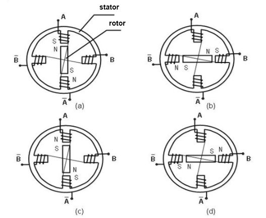
Fig :phases of operating stepper motor
Q4. State and explain Brushless DC motor constructional features?
Ans:
1. BLDC motors can be constructed in different physical configurations. Depending on the stator windings, these can be configured as single-phase, two-phase, or three-phase motors.
2. However, three-phase BLDC motors with permanent magnet rotor are most commonly used.
A. Stator
1. Stator of a BLDC motor made up of stacked steel laminations to carry the windings. These windings are placed in slots which are axially cut along the inner periphery of the stator.
2. These windings can be arranged in either star or delta. However, most BLDC motors have three phase star connected stator.
3. Each winding is constructed with numerous interconnected coils, where one or more coils are placed in each slot. In order to form an even number of poles, each of these windings is distributed over the stator periphery.
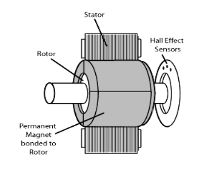
Fig : brushless DC motor
4. The stator must be chosen with the correct rating of the voltage depending on the power supply capability. For robotics, automotive and small actuating applications, 48 V or less voltage BLDC motors are preferred.
5. For industrial applications and automation systems, 100 V or higher rating motors are used.
B :Rotor
1.BLDC motor incorporates a permanent magnet in the rotor. The number of poles in the rotor can vary from 2 to 8 pole pairs with alternate south and north poles depending on the application requirement.
2. In order to achieve maximum torque in the motor, the flux density of the material should be high.
3. A proper magnetic material for the rotor is needed to produce required magnetic field density.
C: Hall Sensors
1. Hall sensor provides the information to synchronize stator armature excitation with rotor position. Since the commutation of BLDC motor is controlled electronically, the stator windings should be energized in sequence in order to rotate the motor.
2. Before energizing a particular stator winding, acknowledgment of rotor position is necessary. So the Hall Effect sensor embedded in stator senses the rotor position.
3. Most BLDC motors incorporate three Hall sensors which are embedded into the stator. Each sensor generates Low and High signals whenever the rotor poles pass near to it.
4. The exact commutation sequence to the stator winding can be determined based on the combination of these three sensor’s response.
Q5. Explain Armature reaction in brief?
Ans:
1. The effect of Armature (stator) flux on the flux produced by the rotor field poles is called Armature Reaction.
2. When the current flows through the armature winding of an alternator, a flux is produced by the resulting MMF.
3. This armature flux reacts with the main pole flux, causing the resultant flux to become either less than or more than the original main field flux.
For simplicity, we consider a 3 phase, 2 pole alternator shown in the figure below.
4. The winding of each pole is assumed to be concentrated, but the effects of armature reaction will be the same as if a distributed winding were also used. The armature reaction in synchronous machine affects the main field flux and vary differently for different power factors.
5. Here armature reaction is discussed for following three conditions, namely unity power factor, zero power factor lagging and zero power factor leading.
6. The power factor can be defined as the cosine of the angle between the armature phase current and the induced EMF in the armature conductor in that phase.
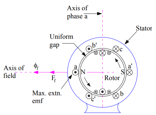
Fig : 3 phase 2 pole alternator
Q6. State and derive equation Synchronous impedance?
Ans:
1. The actual generated voltage consists of the summation of two component voltages. One of these components voltages is the voltage that would be generated if there were no armature reaction.
2. It is the voltage that would be generated because of only field excitation. This component of the generated voltage is called the excitation voltage, Eexc.
3. The other component of the generated voltage is called armature reaction voltage, EAR.
4. This is the voltage that must be added to the excitation voltage to take care of the effect of armature reaction upon the generated voltage.

5. Since armature reaction results, in a voltage effect in circuit caused bu change in flux by current in the same circuit, its effect is of the nature of an inductive reactance .therefore EAR is equivalent to a voltage of inductive reactance and

6. The inductive Reactance XAR is a fictitious reactance which will result in a voltage in armature circuit to account for the effect of armature reaction upon the voltage relations of the armature circuit.
7. Therefore armature reaction voltage can be modelled as in inductor in series with internal generated voltage.
8. In additional to the effect of armature reaction, the stator winding also has a self-inductance and resistance.
Let La = self-inductance of stator winding.
Xa = self-reactance of stator winding.
Ra = armature (stator) resistance.
The terminal voltage V is given by

where
RaIa = armature resistance drop
Xa Ia = armature leakage reactance drop
XAR Ia = armature reaction voltage
9. The armature reaction effect and the leakage flux effect in the machine are both represented by inductive reactance . therefore, it is customary to combine them into a single reactance, is called the synchronous reactance of the machine, Xs.
 …… (4)
 …..(5)


The impedance Zs is called synchronous impedance.
10. The synchronous Reactance Xs is the fictitious reactance employed to account for voltage effects in the armature circuit produced by the actual armature leakage reactance and by the change in air gap flux caused by the armature reaction.
11. Similarly, synchronous impedance Zs is a fictitious impedance employed to account for voltage effects in the armature circuit produced by the actual armature resistance, the actual armature leakage reactance, and the change in air gap flux produced by armature reaction
Q7. State and explain the methods for Determination of Voltage Regulation?
Ans: The following methods are used to determine the voltage regulation of smooth cylindrical rotor type alternators.
A. Direct Load test
B. Indirect methods
A. Direct Load test :
1. The alternator is run at synchronous speed and its terminal voltage is adjusted to its rated value V. the load is varied until the ammeter and wattmeter indicate the rated values at the given power factor.
2. Then the load is removed and the speed and field excitation are kept constant. The open circuit and no load voltage Ea is recorded.
3. The voltage regulation found from percentage voltage regulation. The method of direct loading is suitable only from small alternators of power rating less than kVA.
B. Indirect methods:
For Large alternators, the three indirect methods which are used to predetermine the voltage regulation smooth cylindrical type alternators are as following.
1. Synchronous impedance method or EMF method
2. Ampere turn method or EMF method
3. Zero power factor method or Potier method
Q8. Explain Phasor diagram of a Characteristics of Synchronous Motor?
Ans :
1. The phasor diagram of a Characteristics of Synchronous Motor is shown in fig . The theory of these motors has been developed on the basis of synchronous reactance, which takes care of leakage reactance and armature reaction.
2. A salient pole machine, which has a non-uniform air gap, is described by direct and quadrature axis reactance’s.
3. Variation of the armature current of the motor when its excitation is varied is described by V-curves when the motor develops a given power.
The variation of excitation brings about the following:
- Change in armature current
- Change in line power factor
- Slight change in the load angle.
However, there are minimum and maximum excitations for a given power developed.
4. An increase in the mechanical load at constant excitation would tend to retard the rotor.
5. The angle by which the rotor tends to fall behind the no-load position is called the load angle. In the process of attaining a final position the rotor undergoes oscillations which are damped by damper windings.
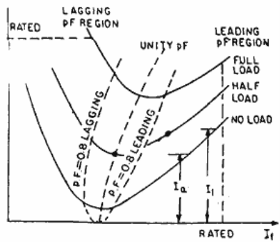
Fig : V curve graph
Q9. State and explain with diagram V- curves?
Ans:
1. V curve is a plot of the stator current versus field current for different constant loads. The Graph plotted between the armatures current Ia and field current If at no load the curve is obtained known as V Curve.
2. Since the shape of these curves is similar to the letter “V”, thus they are called V curve of synchronous motor.
3. The power factor of the synchronous motor can be controlled by varying the field current If.
4. As we know that the armature current Ia changes with the change in the field current If.
5. Let us assume that the motor is running at NO load. If the field current is increased from this small value, the armature current Ia decreases until the armature current becomes minimum.
6. At this minimum point, the motor is operating at unity power factor. The motor operates at lagging power factor until it reaches up to this point of operation.
7. If now, the field current is increased further, the armature current increases and the motor start operating as a leading power factor. The graph drawn between armature current and field current is known as V curve. If this procedure is repeated for various increased loads, a family of curves is obtained.
The V curves of a synchronous motor are shown below.

Fig : V curves of synchronous motor
8. The point at which the unity power factor occurs is at the point where the armature current is minimum.
9. The curve connecting the lowest points of all the V curves for various power levels is called the Unity Power Factor Compounding Curve. The compounding curves for 0.8 power factor lagging and 0.8 power factor leading are shown in the figure above by a red dotted line.
10. The loci of constant power factor points on the V curves are called Compounding Curves. It shows the manner in which the field current should be varied in order to maintain constant power factor under changing load.
11. Points on the right and left of the unity power factor corresponds to the over excitation and leading current and under excitation and lagging current respectively.
12. The V curves are useful in adjusting the field current. Increasing the field current If beyond the level for minimum armature current results in leading power factor.
13. Similarly decreasing the field current below the minimum armature current result results in lagging power factor. It is seen that the field current for unity power factor at full load is more than the field current for unity power factor at no load.
Q10. State and explain two reaction theory of salient pole machine?
Ans :
1. The theory proposes to resolve the given armature MMFs into two mutually perpendicular components, with one located along the axis of the rotor of the salient pole. It is known as the direct axis or d axis component.
2. The other component is located perpendicular to the axis of the rotor salient pole. It is known as the quadrature axis or q axis component.
3. The d axis component of the armature MMF Fa is denoted by Fd and the q axis component by Fq. The component Fd is either magnetizing or demagnetizing.
4. The component Fq results in a cross-magnetizing effect. If Ψ is the angle between the armature current Ia and the excitation voltage Ef and Fa is the amplitude of the armature MMF, then


- Salient Pole Synchronous Machine Two Reaction Theory:
1. In the cylindrical rotor synchronous machine, the air gap is uniform. The pole structure of the rotor of a salient pole machine makes the air gap highly non-uniform.
2. Consider a 2 pole, salient pole rotor rotating in the anticlockwise direction within a 2 pole stator as shown in the figure below.
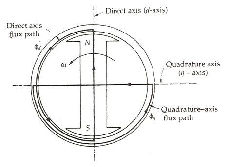
Fig : salient pole rotor rotating anticlockwise in 2 pole stator
3. The axis along the axis of the rotor is called the direct or the d axis. The axis perpendicular to d axis is known as the quadrature or q axis.
4. The direct axis flux path involves two small air gaps and is the path of the minimum reluctance. The path shown in the above figure by ϕq has two large air gaps and is the path of the maximum reluctance.
The rotor flux BR is shown vertically upwards as shown in the figure below.
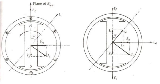
Fig : flux showing diagram( upwards )
5. The rotor flux induces a voltage Ef in the stator. The stator armature current Ia will flow through the synchronous motor when a lagging power factor load is connected it.
6. This stator armature current Ia lags behind the generated voltage Ef by an angle Ψ.
7. The armature current produces stator magneto motive force Fs. This MMF lags behind Ia by angle 90 degrees. The MMF FS produces stator magnetic field BS long the direction of Fs.
8. The stator MMF is resolved into two components, namely the direct axis component Fd and the quadrature axis component Fq.
Unit - 5
Undecidability
In 1936, a technique named as lambda-calculus was created by Alonzo Church
Within which the Church numerals area unit well outlined, i.e. the encryption of
Natural numbers. Additionally, in 1936, mathematician machines (earlier known as
Theoretical model for machines) was created by mathematician, that’s used for
Manipulating the symbols of string with the assistance of tape.
Church - Turing Thesis:
Turing machine is outlined as associate degree abstract illustration of a computer
Like hardware in computers. Mathematician planned Logical Computing Machines
(LCMs), i.e., mathematician’s expressions for Turing Machines. This was done to
Outline algorithms properly. So, Church created a mechanical methodology named
As ‘M’ for manipulation of strings by mistreatment logic and arithmetic.
This methodology M should pass the subsequent statements:
• Number of directions in M should be finite.
• Output ought to be made when playing a finite variety of steps.
• It mustn’t be imagined, i.e., is created in the world.
• It mustn’t need any complicated understanding.
Using these statements Church planned a hypothesis known as Church’s
Mathematician thesis that may be expressed as: “The assumption that the intuitive
Notion of estimable functions is known with partial algorithmic functions.”
In 1930, this statement was initial developed by Alonzo Church and is typically
Brought up as Church’s thesis, or the Church-Turing thesis. However, this hypothesis
Cannot be proved .
The algorithmic functions are estimable when taking following assumptions:
1. Every and each operate should be estimable.
2. Let ‘F’ be the estimable operation and when playing some elementary operations to ‘F’, it’ll rework a replacement operation ‘G’ then this operates ‘G’ mechanically becomes the estimable operation.
3. If any operates that follow on top of 2 assumptions should be states as
Estimable function.
What Justifies the Church-Turing Thesis?
Stephen Kleenewho coined the term “Church-Turing thesis “catalogued four sorts of argument for CTT-O:
Initial, the argument from non-refutation points out the thesis has ne’er been refuted, despite sustained (and ongoing) makes an attempt to search out a disproof (such because the makes an attempt by László Kalmár and, additional
Recently, by Doukas Kapantais).
Second, the argument from confluence points to the
Very fact that the assorted characterizations of computability, whereas differing in
Their approaches and formal details, end up to comprehend the exact same category
Of estimable functions. Four such characterizations were bestowed (independently)
In 1936 and like a shot proved to be extensionally equivalent: mathematician
Computability, Church’s -definability, Kleene’s algorithmic functions, and Post’s
Finitary combinatory processes.
Third is associate degree argument typically brought up today as “Turing’s analysis.”
Mathematician known as it merely argument “I”; stating 5 terribly general and
Intuitive constraints or axioms the human pc is also assumed to satisfy: “The behavior
Of the pc at any moment is set by the symbols that he’s perceptive, associate
Degreed his “state of mind” at that moment”.
The second a part of mathematician’s argument I may be a demonstration that every
Operate computed by any human pc subject to those constraints is additionally
Estimable by a computing machine; it’s not tough to visualize that every of the
Computer’s steps is mimicked by the Turing machine, either during a single step or
By means that of a series of steps.
Fourth during this catalog of issues supporting CTT-O area unit arguments from first-
Order logic. They’re typified by a 1936 argument of Church’s and by Turing’s
Argument II, from Section nine of Turing’s 1936 paper. In 2013, Saul Kripke
Bestowed a reconstruction of Turing’s argument II, which works as follows:
Computation may be a special variety of mathematical deduction; each|and each}
Mathematical deduction and thus every computation can be formalized as a legitimate deduction within the language of first-order predicate logic with identity (a step Kripke brought up as “Hilbert’s thesis”); following Gödel’s completeness theorem, every computation is so formalized by a obvious formula of first-order logic; and each computation will thus be disbursed by the universal computing machine. This last step concerning the universal computing machine is secured by a theorem proved by Turing: each obvious formula of first-order logic is proved by the universal computing machine.
The third and fourth of those arguments offer justification for CTT-O however not for
CTT-A. As Robin Gandy found out, the third argument Turing’s I contains “crucial
Steps ... Wherever he [Turing] appeals to the very fact that the calculation is being
Disbursed by a person’s being.” as an example, mathematician assumed “a soul will
Solely write one image at a time, “associate degreed Gandy noted this assumption
Cannot be carried over to a parallel machine that “prints an discretionary variety of
Symbols at the same time.” In Conway’s Game of Life, for example, there’s no edge
On the number of cells that conjure the grid, nevertheless the symbols altogether the
Cells area unit updated at the same time. Likewise, the fourth argument (Turing’s II)
Involves the claim that computation may be a special variety of formal proof,
However, the notion of proof is in and of itself associated with what a person’s
Mathematician and not some oracle can prove.
It is thus perhaps not too surprising that the third and fourth arguments in this catalog seldom if ever appear in logic and computer science textbooks. The two arguments that are always given for the Church-Turing thesis (in, for example, Lewis and Papadimitriou are confluence and non-refutation. Yet both those arguments are
Merely inductive, whereas the third and fourth arguments are deductive in nature.
However, a number of attempts have sought to extend Turing’s axiomatic analysis to
Machine computation; for example, Gandy broadened Turing’s analysis in such a
Way that parallel computation is included, while Dershowitz and Gurevich gave a
More general analysis in terms of abstract state machines. We return to the topic of
Extending the analysis to machine computation later in this article but first address
The important question of whether CTT-O is mathematically provable.
Key takeaway:
- Turing machine is outlined as associate degree abstract illustration of a computer like hardware in computers.
- A common one is that a Turing machine can perform any good computation.
- The Church-Turing thesis is often misunderstood, especially in the philosophy of mind in recent writing.
A Turing Machine is the mathematical tool equivalent to a digital computer. It was
Suggested by the mathematician Turing in the 30s, and has been since then the
Most widely used model of computation in computability and complexity theory.
The model consists of an input output relation that the machine computes. The input
Is given in binary form on the machine’s tape, and the output consists of the contents
Of the tape when the machine halts.
What determines how the contents of the tape change is a finite state machine (or
FSM, also called a finite automaton) inside the Turing Machine. The FSM is
Determined by the number of states it has, and the transitions between them.
At every step, the current state and the character read on the tape determine the
Next state the FSM will be in, the character that the machine will output on the tape
(possibly the one read, leaving the contents unchanged), and which direction the
Head moves in, left or right.
The problem with Turing Machines is that a different one must be constructed for
Every new computation to be performed, for every input output relation.
This is why we introduce the notion of a universal turing machine (UTM), which
Along with the input on the tape, takes in the description of a machine M. The UTM
Can go on then to simulate M on the rest of the contents of the input tape. A universal turing machine can thus simulate any other machine.

Fig 1: universal Turing machine
I learned about Turing Machines the first term of my sophomore year at MIT (Fall
96), in 6.004 (Computational Structures), the best class ever conceived. It was late
One night when I was starting my problem set on writing a turing machine to compute some operation. To test my result, I figured I could code up a Universal Turing Machine in Scheme to help me do my problem set. I could then feed it my
Description and a sample input, and it would simulate any machine for me. To me
Surprise within two hours, the program was working, and i could start the rest of me
Problem set
Program used to check solutions to a 6.004 problem set
;; Simulation of a Turing machine
;; global variables used by procedures.
;; Those are changed at every step, and must be reinitialized before running a
Different
;; example, by running: (setup state-graph tape initial-state initial-position)
(define *machine* ‘()); the machine currently running
(define *state* ‘s1); the state at which the current machine is at
(define *position* 0); the position at which the tape is reading
(define *tape* # ()); the tape that the current machine is currently running on
;; The following procedure takes in a state graph (see examples below), and turns it
;; to a machine, where each state is represented only once, in a list containing:
;; a structure of the form:
;; ((state (in out move next-state) (in out move next-state) (in out move next-state))
;; (state2 (in out move next-state))
;; (state3 (in out move next-state) (in out move next-state)))
;;
;; Each state name is followed by a list of combinations of inputs (read on the tape)
;; and the corresponding output (written on the tape), direction of motion (left or right),
;; and next state the machine will be in.
;;
;; Here’s the machine returned by (initialize flip) (as defined at the end of this file)
;; ((s4 (0 0 l h))
;; (s3 (1 1 r s4) (0 0 l s3))
;; (s2 (0 1 l s3) (1 0 r s2))
;; (s1 (0 1 r s2) (1 1 l s1)))
(define (initialize state-graph)
(define (extend machine states-to-go)
(if (null? states-to-go)
Machine
(let ((cur-state (first states-to-go))
(matched #f))
(extend (begin (for-each (lambda (state)
(if (equal? (state-name state) (car cur-state))
(begin (set! matched #t)
(set-cdr! state (cons (cdr cur-
State) (cdr state))))))
Machine)
(if matched
Machine
(cons (list (state-name cur-state)
(cdr cur-state))
Machine)))
(cdr states-to-go)))))
(extend ‘() state-graph))
;; Setup is a handy procedure to initialize and test a new graph.
;; It will take care of reading the graph, and initializing the global variables.
;; Once this is done, all one has to do is run the program (run) or move step
;; by step (step) for debugging
(define (setup state-graph tape state position)
(set! *machine* (initialize state-graph))
(set! *tape* tape)
(set! *state* state)
(set! *position* position))
;; The following are the procedures that implement the Turing machine.
;; It can write, read, move, etc...
(define (set-state! state)
(set! *state* state))
(define (set-position! position)
(set! *position* position))
(define (do-move move-to-make)
(cond ((equal? move-to-make ‘R) (move-right))
((equal? move-to-make ‘L) (move-left))
(else (error “i don’t know what move to make:”move-to-make))))
(define (move-right)
(set! *position* (+ *position* 1)))
(define (move-left)
(set! *position* (- *position* 1)))
(define (write output)
(vector-set! *tape* *position* output))
(define (read)
(vector-ref *tape* *position*))
Key takeaway:
- A Turing Machine is the mathematical tool equivalent to a digital computer.
- The model consists of an input output relation that the machine computes.
- A universal turing machine can thus simulate any other machine.
The resolving Language
1. Reducing One drawback to a different
Suppose we’ve Associate in Nursing algorithmic program A to rework instances of 1
Drawback P1 to instances of another drawback P2 in such the way that a string w is
In P1 if and on condition that the reworked string A(w) is in P2. What this means is
That we are able to solve instances of drawback P1 by changing them to instances of
Drawback P2 so mistreatment the answer to drawback P2 to answer the first
Question. If we are able to try this, then we are going to say that A may be a
Reduction of P1 to P2.
Note that a discount from P1 to P2 should flip each instance of P1 with a
Affirmative Associate in Nursingswer to an instance of P2 with a affirmative answer,
And each instance of P1 with a no Associate in Nursingswer to an instance of P2
With a no answer.
We are going to oftentimes use this method to point out that drawback P2 is as
Exhausting as drawback P1.
The direction of the reduction is very important.
For instance, if there’s a discount from P1 to P2 and if P1 isn’t algorithmic, then P2
Cannot be algorithmic. (Why?)
Similarly, if there’s a discount from P1 to P2 and if P1 isn’t recursively
Calculable, then P2 cannot be recursively calculable. (Why?)
2. Enumerating the Binary Strings
In several proofs involving Alan Mathison Turing machines, we' d like to enumerate the binary strings and encipher computing machines in order that WIll|we are able to} seek advice from the ith binary string as wi and also the ith Alan Mathison Turing machine as Mi.
The binary strings area unit straightforward to enumerate. If w may be a binary
String, we have a tendency to shall treat 1w because the binary number i thus we are
Able to decision w the ith string.
Mistreatment this coding, the empty string is that the 1st string, zero the second,
One the third, 00 the fourth, 01 the fifth, and so on. Henceforward WIll|we'll|we are going to} seek advice from the ith string as wi.
3. Codes for Alan Mathison Turing machines
We are going to currently outline a code for all Alan Mathison Turing machines with
The input alphabet in order that every computing machine may be painted by a
Binary string. This may enable United States to speak regarding the ith computing
Machine as Mi. We are going to adopt the subsequent conventions:
We have a tendency to assume the states area unit q1, q2, . . ., qr for a few r. We
Have a tendency to assume q1 can continually be the beginning state. We have a
Tendency to assume q2 are going to be the sole acceptive state. We'd like only 1
Acceptive state if we have a tendency to assume the computing machine halts
Whenever it enters Associate in Nursing acceptive state.
We have a tendency to assume the tape symbols area unit X1, X2, . . . , Xs for a few
s. We have a tendency to assume X1 is zero, X2 is 1, and X3 is that the blank.
We have a tendency to assign integers D1 and D2 to the tape head directions left
And right.
Currently we are able to encipher a transition rule δ (qi, Xj) = (qk, Xl, Dm) as a binary
String C of the shape
0i10j10k 10l10m
Suppose their area unit n transition rules. The code for the complete computing
Machine is going to be the concatenation of the codes for all of the transitions (in
Some order) separated by pairs of 1’s:
C111C211 … Cn-111Cn
Note that there may be several encodings for identical computing machine.
We are able to encipher a try (Mi, w) consisting of a computing machine and a string
By appending 111 to the coding of the computing machine so appending the string
w.
4. The resolving Language Ld isn’t Recursively calculable
We have a tendency to outline Ld, the resolving language, as follows:
Let w1, w2, w3, . . . Be Associate in Nursing enumeration of all binary strings.
Let M1, M2, M3, . . . Be Associate in Nursing enumeration of all Alan Mathison
Turing machines.
Let Ld = American state | Wisconsin isn’t in L(Mi) }.
Theorem: Ld isn’t a recursively calculable language.
Proof:
Suppose Ld = L(Mi) for a few atomic number 69 Mi.
This offers rise to a contradiction. Take into account what Mi can do on Associate in
Nursing input string Wisconsin.
If Mi accepts Wisconsin, then by definition Wisconsin cannot be in Ld.
If Mi doesn’t accept Wisconsin, then by definition Wisconsin is in Ld.
Since Wisconsin will neither be in Ld nor not be in Ld, we have a tendency to
Should conclude there’s no computing machine which will outline Ld.
Identifying languages (or problems*) as decidable, undecidable or part decidable
May be a quite common question in GATE. With correct data and ample expertise,
This question becomes terribly straightforward to unravel.
Let’s begin with some definitions:-
Decidable language -A call drawback P is claimed to be decidable (i.e., have
Associate in Nursing algorithm)
If the language L of all affirmative instances to P is decidable.
Example- (I) (Acceptance drawback for DFA) Given a DFA will it settle for a given
Word?
(II) (Emptiness drawback for DFA) Given a DFA will it settle for any word?
(III) (Equivalence drawback for DFA) Given 2 DFAs, do they settle for the
Same language?
Undecidable language -– a call drawback P is claimed to be undecidable if the
Language L of all yes instances to P isn’t decidable or a language is undecidable if it’s not decidable.
Associate in Nursing undecidable language perhaps a part decidable language or
One thing else however not decidable. If a language isn’t even part decidable , then
There exists no computing machine for that language.
Partially decidable or Semi-Decidable Language -– a call drawback P is claimed to
Be semi-decidable (i.e., have a semi-algorithm) if the language L of all affirmative
Instances to P is RE. A language ‘L’ is part decidable if ‘L’ may be a RE however not
REC language.
Recursive language(REC) – A language ‘L’ is alleged to be algorithmic if there exists
a computing device which is able to settle for all the strings in ‘L’ and reject all the
Strings not in ‘L’. The computing device can halt on every occasion and provides
Associate answer(accepted or rejected) for every and each string input. A language
‘L’ is decidable if it’s a algorithmic language. All decidable languages area unit
Algorithmic languages and vice-versa.
Recursively countable language(RE) – A language ‘L’ is alleged to be a recursively
Countable language if there exists a computing device which is able to settle for (and
So halt) for all the input strings that area unit in ‘L’ however could or might not halt for
All input strings that aren’;t in ‘L’. By definition , all REC languages {are also|also area
Unit|are} RE languages however not all RE languages are REC languages.
Now lets solve some examples –
a method to unravel decidability issues is by {trying|making associate
Attempt|attempting} to cut back an already illustrious undecidable downside to the
Given downside. By reducing a retardant P1 to P2, we tend to mean that we tend to
Try to unravel P1 by mistreatment the formula wont to solve P2.
If we are able to cut back associate already illustrious undecidable downside P1 to a
Given downside P2 , then we are able to sure enough say that P2 is additionally
Undecidable. If P2 was decidable, then P1 would even be decidable however that
Becomes a contradiction as a result of P1 is understood to be undecidable.
For example:
1. Given a computing device ‘M’, we want to seek out out whether or not a state ‘Q’
Is ever reached once a string ‘w’ is entered in ‘M’. This downside is additionally
Referred to as the ‘State Entry problem’.
Now lets try and cut back the Halting downside to the State Entry downside. A
Computing device solely halts once a transition operate ? (qi , a) isn't outlined.
Modification each indefinable operate ?(qi,a) to ?(qi,a) = (Q, a, L or R). Note that the
State letter will solely be reached once the computing device halts.
Suppose we’ve have associate formula for finding the State Entry downside which is
Able to halt on every occasion and tell United States of America whether or not state
Letter will be reached or not. By telling United States of America that we are able to
Or cannot reach state letter on every occasion, it’s telling United States of America that the computing device can or won’t halt, every time. However, we all know that’s impractical as a result of the halting downside is undecidable. Meaning that us
Assumption that there exists associate formula that solves the State Entry downside
And halts and offers United States of America a solution on every occasion, is false.
Hence, the state entry downside is undecidable.
Key takeaway:
- This techniques was introduced in 1873 by Georg Cantor
- As a way of showing that the (infinite) set of real numbers is larger than the (infinite) set of integers
Rice theorem states that any non-trivial linguistics property of a language that is
Recognized by a information processing system is undecidable. A property, P, is that
The language of all Alan Mathison Turing machines that satisfy that property.
Formal Definition
If P may be a non-trivial property, and therefore the language holding the property,
Lp , is recognized by information processing system M, then record = L(M) ∈ P is
Undecidable.
Description and Properties
• Property of languages, P, is solely a collection of languages. If any language
Belongs to P (L ∈ P), it's aforesaid that L satisfies the property P.
• A property is named to be trivial if either it's not happy by any recursively
Numerable languages, or if it’s happy by all recursively numerable languages.
• A non-trivial property is happy by some recursively numerable languages and
Aren’t happy by others. Formally speaking, in an exceedingly non-trivial property,
Wherever L ∈ P, each the subsequent properties hold:
o Property one one There exists Alan Mathison Turing Machines, M1 and M2
That acknowledge constant language, i.e. either (, ∈ L) or (, ∉ L)
o Property two two There exists Alan Mathison Turing Machines M1 and M2,
Wherever M1 acknowledges the language whereas M2 doesn’t, i.e. ∈ L and ∉ L
Proof
Suppose, a property P is non-trivial and φ ∈ P.
Since, P is non-trivial, a minimum of one language satisfies P, i.e., L(M0) ∈ P , ∋
Information processing system M0.
Let, w be associate degree input in an exceedingly specific instant and N may be a
Information processing system that follows −
On input x
● Run M on w
● If M doesn’t settle for (or does not halt), then don't settle for x (or don’t halt)
● If M accepts w then run M0 on x. If M0 accepts x, then settle for x.
A perform that maps associate degree instance ATM = M accepts input w to a N such
● If M accepts w and N accepts constant language as M0, Then L(M) = L(M0) ∈ p
● If M doesn’t settle for w and N accepts φ, Then L(N) = φ ∉ p
Since ATM is undecidable and it is reduced to record, record is additionally undecidable.
Decidable issues
A problem is decidable if we will construct a information processing system which
Can halt in finite quantity of your time for each input and provides answer as ‘yes’ or
‘no’. A decidable downside has associate degree formula to work out the solution for
a given input.
Examples
• Equivalence of 2 regular languages: Given 2 regular languages, there’s
Associate degree formula and information processing system to make a decision
Whether or not 2 regular languages ar equal or not.
• Finiteness of normal language: Given an everyday language, there’s
Associate degree formula and information processing system to make a decision
Whether or not regular language is finite or not.
• Emptiness of context free language: Given a context free language, there’s
Associate degree formula whether or not CFL is empty or not.
Undecidable issues
A problem is undecidable if there’s no information processing system which can
Continuously halt in finite quantity of your time to provide answer as ‘yes’ or ‘no’.
Associate degree undecidable downside has no formula to work out the solution for a
Given input.
Examples
• Ambiguity of context-free languages: Given a context-free language, there’s
No information processing system which can continuously halt in finite quantity of
Your time and provides answer whether or not language is ambiguous or not.
• Equivalence of 2 context-free languages: Given 2 context-free languages,
There’s no information processing system which can continuously halt in finite
Quantity of your time and provides answer whether or not 2 context free languages ar
Equal or not.
• Everything or completeness of CFG: Given a CFG and input alphabet,
Whether or not CFG can generate all doable strings of input alphabet (∑*)is
Undecidable.
• Regularity of CFL, CSL, REC and REC: Given a CFL, CSL, REC or REC,
Determinative whether or not this language is regular is undecidable.
Note: 2 in style undecidable issues ar halting downside of metal and angel dust (Post
Correspondence Problem). Semi-decidable issues
A semi-decidable downside is set of undecidable issues that information processing
System can continuously halt in finite quantity of your time for answer as ‘yes’ and
Will or might not halt for answer as ‘no’.
Rice’s Theorem
Every non-trivial (answer isn’t known) downside on algorithmic numerable languages is undecidable.e.g.; If a language is algorithmic numerable, its complement are going to be algorithmic numerable or not is undecidable.
Reducibility and Undecidability
Language A is reducible to language B (represented as A≤B) if there exists a
Perform f which can convert strings in an exceedingly to strings in B as:
w ɛ A <=> f(w) ɛ B
Theorem 1: If A≤B and B is decidable then A is additionally decidable.
Theorem 2: If A≤B and A is undecidable then B is additionally undecidable.
Key takeaway:
- The Rice theorem states that every non-trivial semantic characteristic of a language that a Turing machine recognises is undecidable.
- If we can create a Turing machine that will stop for each input in a finite amount of time and respond as 'yes' or 'no', a problem is determinable.
- An algorithm for determining the answer to a given input has a decidable.
For an undecidable language, there is no Turing Machine which accepts the
Language and makes a decision for every input string w (TM can make decision for
Some input string though).
A decision problem P is called “undecidable” if the language L of all yes instances to P is not decidable. Undecidable languages are not recursive languages, but sometimes, they may be recursively enumerable languages.
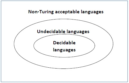
Fig 2: undecidable language
Example
● The halting problem of Turing machine
● The mortality problem
● The mortal matrix problem
● The Post correspondence problem, etc.
- Halting problem of turing machine
Input : A machine with Turing and an input string w.
Problem : Does the Turing machine complete the w-string computation in a finite number of steps? Either yes or no must be the answer.
Proof : We will first assume that there is such a Turing machine to solve this problem, and then we will demonstrate that it contradicts itself. This Turing machine would be called a Halting machine that produces in a finite amount of time a 'yes' or 'no'. The performance comes as 'yes' if the stopping machine finishes in a finite amount of time, otherwise as 'no'.
The Halting Computer block diagram is as follows.

Fig 3: block diagram of halting
We're now going to build an inverted stopping machine (HM)' as -
● If H returns YES, then loop forever.
● If H returns NO, then halt.
The following is a 'Inverted Stopping Unit' block diagram -
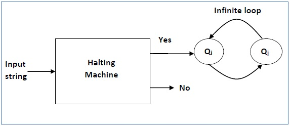
Fig 4: inverted stopping unit
In addition, as follows, a machine (HM)2 whose input itself is constructed
● If (HM)2 halts on input, loop forever.
● Else, halt.
We have a contradiction here. The stopping question is therefore undecidable
Key takeaway:
- If there is no Turing machine, a problem is undecidable, which will always stop in a finite amount of time to respond as 'yes' or 'no'.
- There is no algorithm for an undecidable problem to evaluate the answer to a given input.
References:
- John E. Hopcroft, Rajeev Motwani and Jeffrey D. Ullman, Introduction to Automata Theory, Languages, and Computation, Pearson Education
Asia.
2. Harry R. Lewis and Christos H. Papadimitriou, Elements of the Theory
Of Computation, Pearson EducationAsia.
3. John Martin, Introduction to Languages and the Theory of Computation, Tata McGraw Hill.