Unit - 1
Measurement and Error
1.1.1 Definition
Measurement error is defined as the difference between true or actual value and measured value. The true value represents the average of infinite number of measurements and the measured value is the precise value.
1.1.2 Accuracy and Precision
Accuracy: It is the closeness with which the instrument reading approaches the true value of the quantity being measured. Thus, accuracy of measurement means conformity to truth.
Precision: It is a measure of reproducibility of the measurements that is given a fixed value of quantity precision is a measure of degree of agreement within a group of measurements. The term precise means clearly or sharply defined.
1.1.3 Significant figures
Significant figures convey actual information regarding the magnitude and the measurement precision of quantity. The more the significant figures the greater the precision of measurement.
For example, if a voltage is specified as 256 V its value should be taken as closer to 256V than to either 257 or 255V. If the value of the voltage is described as 256.0V it means that the voltage is closer to 256.0V than it is to 256.1 V or 255.9V. In 256 there are three significant figures while in 256.0 there are four.
Problem:
State the number of significant figures in each of the following numbers.
(a) 302 A (b) 302.10V (c) 0.00030 Ω (d) 0.0000300kΩ (e) 5.01 x 10 4 (f) 50100
Solution:
(a) The number is 302. This means that that it is more lose to 302 that to either 301 or 303. Thus, this number has 3 significant figures.
(b) The number involved is 302.10. Therefore, it is closer to 302.10 than either to 301.09 or to 302.11. Thus, it has 5 significant figures.
(c) The number is 0.00030. This means that it is closer to 0.0030 than either to 0.00029 or 0.00031. Thus, it has 5 significant figures.
(d) The resistance is 0.00003 MΩ. This can be written as 30Ω. Thus, it is closer to 30 than either 29 or 31. Therefore it has 2 significant figures. The zeros to the left of 3 are due to large size of unit.
(e) The number under considerations is 5.01 x 10 4. Hence it is closer to 5.01 x 10 4 than to either 5.00 x 10 4 or 5.02 x 10 4. Thus, it has 3 significant figures.
(f) The number is 50100. This is a large number, and a situation may arise that causes uncertainty.
1.1.4 Types of Errors
Errors may rise from different sources and are classified as:
- Gross Errors
- Systematic errors
- Random Errors
Gross Errors: This class of errors covers human mistakes in reading instruments and recording and calculating measurement results. The responsibility of the mistake normally lies with the experimenter. The experimenter may grossly misread the scale.
Example
Due to some reasons, he might have read the temperature as 31.5 while the actual reading may be 21.5. He may transpose the reading while recording. For example, he may read 25.8 as 25.8. If human beings are involved gross errors will be committed.
Systematic Errors
These types of errors are divided into three categories:
- Instrument errors
- Environmental errors
- Observational errors
Instrumental Errors
These errors arise due to three main reasons:
(i) Due to inherent shortcomings in the instrument
(ii) Due to misuse of the instrument
(iii) Due to loading effects of instruments.
(1) Inherent short comings of instrument because of their mechanical structure. They may be due to construction, calibration or operation of the instruments or measuring device.
While making precision measurements we recognize the possibility of such errors as it is often possible to eliminate them by using the following methods:
(1) The procedure of measurement must be carefully planned. Substitution methods or calibration against standards may be used for the purpose.
(2) Correct factors should be applied after determining the instrumental errors.
(3) The instruments may be re-calibrated carefully.
(2) Misuse of instrument:
A good instrument used in an unintelligent way may give erroneous results.
Examples which may be cited for this misuse of instrument may be failure to adjust the zero of instruments, poor initial adjustments using leads too high a resistance and so on.
(3) Loading effects: One of the most common errors committed by beginners is the improper use of an instrument for measurement work. For example, a well calibrated voltmeter may give a misleading voltage reading when connected across high resistance circuit. However, when the same voltmeter is connected in low resistance circuit it may give dependable reading. These examples illustrate that the voltmeter has loading effect on the circuit.
Problem:
A voltmeter having a sensitivity of 1000Ω/V reads 100V on its 150V scale when connected across an unknown resistor in series with a milliammeter.
When the milli-ammeter reads 5mA calculate
(a) Apparent resistance of the unknown resistor
(b) Actual resistance of the unknown resistor
(c) Error due to the loading effect of voltmeter.
Total circuit resistance
RT = ET/IT = 100 / 5 x 10 -3 = 20 x 10 3 Ω
Neglecting the resistance of milli-ammeter the value of unknown resistor is
Rs = 20kΩ
(b) Resistance of voltmeter = Rs = 1000 x 150 x 10 3 = 150 k Ω
As the voltmeter is in parallel with unknown resistance, we have.
RT = Rx Rv / Rx + Rv
Or unknown resistance Rx = RT RV / RV – RT = 20 x 150 / 150 – 20 = 23.077 kΩ
(c ) Percentage error = erroneous quantity – true quantity / true quantity x 100
= 20 -23.077/23.077 x 100 = 13.33 %
Key Take Away:
Measurement Error also called Observational Error is the difference between a measured quantity and its true value. It includes random error naturally occurring errors that are to be expected with any experiment and systematic error caused by a mis-calibrated instrument that affects all measurements.
Standards of Measurement are classified into the following categories:
(i) International Standards (ii) Primary Standards
(iii)Secondary Standards (iv) Working standards
Classification of Standards
The international standards are defined on the basis of international agreement. They represent the units of measurements which are closest to the possible accuracy attainable with present day technological and scientific methods .
International standards are checked and evaluated regularly against absolute measurements in terms of fundamental units.
The international standards are maintained at the International Bureau of Wieghts and Measures and are not available to ordinary user of measuring instruments for purpose of calibration or comparison.
Primary standards:
Primary standards are absolute standards of such high accuracy that can be used as the ultimate reference standards. These standards are maintained by national standards laboratories in different parts of the world. One of the main functions of primary standards is the verification and calibration of secondary standards.
The following points must be taken into consideration when a primary standard is built :
(i) The material should have long time stability
(ii) The temperature co-efficient of the material should be as small as possible.
(iii) The deterioration of materials caused by moisture and other environmental conditions should be eliminated as far as possible.
(iv) The machining of parts should be accurate
(v) The measurement of physical dimension on which the accuracy of the standard depends predominantly should be done with most sosphisticated techniques available.
(vi) The rigidity of the construction should be insured.
Secondary Standard:
The secondary standard are the basic reference standard used in industrial measurement laboratories. The responsibilty of maintainence and calibration of these standards lies with the particular industry involved. These standards are checked locally against reference standards available in the area.
Secondary standards are normally sent periodically to the national standards laboraties for calibration and comparison against primary standards. The secondary standards are sent back to the industry by national laboratories with ceritification as regards their measured vallues in terms of primary standards.
Working Standards :
The working standards are the major tools of measurement laboratory. These standards are used to check and calibrate general laboratory instruments for their accuracy and performance.
For example a manufacturer of precision resistances may use a Standard Resistance in quality control department for checking the values of resistors that are being manufactured.
Electrical Standards
In order to assign values to electrical standards it is necessary to determine only two standards in terms of defining units. From electrical it is possible to assign values to remaining standards. Therefore national laboratories usually maintain standards of emf and resistance and base values of other standards on these two.
All electrical measurements are based upon three fundamental quantities current, resistance and voltage. A system of measurements depends upon definitions of units of these quantities . These three electrical units are not independent but are related by Ohms law: E = IR.
IEEE Standards
The IEEE is a professional association that develops, defines, and reviews electronics and computer science standards. The main mission is to foster technological innovation and excellence for the benefit of humanity."
The history of the IEEE spans back to the 1800s, when electricity started to influence society. In 1884, the AIEE (American Institute of Electrical Engineers) was formed to support electrical innovation. In 1912, the IRE (Institute of Radio Engineers) was created to develop wireless telegraphy standards. In 1963, the two organizations merged to become a single entity – the IEEE. Since then, the organization has established thousands of standards for consumer electronics, computers, and telecommunications.
Key Takeaways:
A measurement standard may also be said to store, embody, or otherwise provide a physical quantity that serves as the basis for the measurement of the quantity.
Ammeter:
An ammeter is an electrical measurement instrument which is used to measure current through a point or wire in a circuit. It is connected in series with the circuit whose current is to be measured.
Hence it should have low electrical resistance. This is essential because they cause small voltage drop and consequently absorb small power.
Ammeter can also be made from a galvanometer by placing a shunt resistance in parallel with the galvanometer.
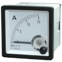
Figure 1. Ammeter
Voltmeter
- A voltmeter is an electrical measurement instrument that is used to measure voltage across two given points in a circuit. It is connected in parallel with the circuit or the part of the circuit whose voltage is to be measured.
- Should have high electrical resistance so that the current drawn by them is small and ultimately the power absorbed is small.
- Voltmeter can also be made from a galvanometer by placing a high resistance in series with the galvanometer.
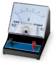
Figure 2. Voltmeter
The permanent magnet moving coil instrument is the most accurate type for dc measurements. The working principle is same as that of d’Arsonval type of galvanometer the difference is that direct reading instrument is provided with pointer and scale.
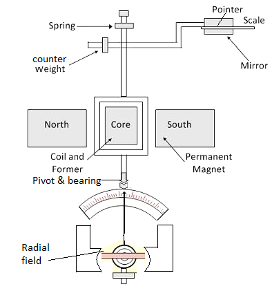
Figure 3. PMMC
The three important torque involved in this instrument are:
Deflecting torque: The force F which will be perpendicular to both the direction of the current flow and the direction of the magnetic field as per Fleming’s left hand rule can be written as
F = NBIL
Where N: turns of wire on the coil
B: flux density in the air gap
I: current in the movable coil
L: vertical length of the coil
Theoretically, the torque that is electro-magnetically torque is equal to the multiplication of force with distance to the point of suspension.
Hence Torque on the left side of the cylinder TL = NBIL x W/2 and torque on right side of the cylinder TR = NBIL x W/2
Therefore, the total torque will be = TL + TR
T = NBILW or NBIA where A is an effective area (A= LxW).
Controlling Torque
This torque is produced by the spring action and opposes the deflection torque so as the pointer can come to rest at the point where these two torques are equal that is Electromagnetic torque = control spring torque. The value of control torque depends on the mechanical design of spiral springs and strip suspensions.
The controlling torque is directly proportional to the angle of deflection of the coil.
Control torque Ct =Cθ where,
θ = deflection angle in radians and C = spring constant Nm /rad
Damping torque
This torque ensures the pointer comes to an equilibrium position that is rest in the scale without oscillating to give an accurate reading. In PMMC as the coil moves in the magnetic field, eddy current sets up in a metal former or core on which the coil is wound or in the circuit of the coil itself which opposes the motion of the coil resulting in the slow swing of a pointer and then come to rest quickly with little oscillation.
Problem:
A permanent magnet moving coil instrument has a coil of dimensions 15mm x 12mm. The flux density in the air gap is 1.8 x 10 -3 Wb/m2 and the spring constant is 0.14 x 10 -6 Nm/rad. Determine the number of turns required to produce an angular deflection of 90 degrees when a current of 5mA is flowing through the coil.
Solution:
Deflection  = 90 o = π/2 rad.
At equilibrium Td=Tc, NBl dl = K 
Number of turns = k / Bl dI = 0.14 x 10 -6 x π/2 / 1.8 x 10 -3 x 15 x 10 -3 x 12 x 10 -3 x 5 x 10 -3 = 136.
Moving Iron (attraction and repulsion type )
General Torque Equation:
An expression for the torque of moving iron instrument may be derived by considering the energy relations when there is small increment in current supplied to the instrument. When this happens there will be small deflection d and some mechanical work.
Let Td = deflecting torque
Mechanical work done = Td . d
Along side there will be change in the energy stored owing to inductance.
Suppose initial current is I, the instrument inductance L and deflection  If the current increases by dI then the deflection changes by d
 and inductance by dL. To increment dl in the current there must be an increase in the applied voltage given by
e = d/dt(LI) = I dL/dt + L dI/dt
The electrical energy supplied eIdt = I2 dL + IL dI
The stored energy changes from ½ I2 L to ½ (I +dI) 2 (L +dL)
Hence the change in stored energy = ½ ( I2 + 2IdI + dI2) (L+dL) – ½ I2 dL
From the principle of conservation of energy
Electrical energy supplied = increased in stored energy + mechanical work done.
I2 dL + IL dI = IL dI = ½ I2 dL + Td d
Td d = ½ I2 dL
Or Deflecting torque Td = ½ I2 dL/d
T is in newton metre I in ampere L is in henry and  in radian .
The moving system is provided with control springs and it turns the deflecting torque Td is balanced by controlling torque Tc.
Controlling torque Tc = K where K = control spring constant Nm/rad
 = deflection
At equilibrium or final steady position Tc = Td
Or k = ½ I 2 dL/d
 or deflection
  = ½ I2 /K dL/d
Hence deflection is proportional to the square of the rms value of the operating current.
Attraction type:
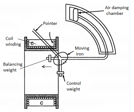
Figure 4. Attraction type
The coil is flat and has narrow slot like opening. The moving iron is flat disc or sector eccentrically mounted. When the current flows through the coil magnetic field is produced and the moving iron moved from the weaker filed outside the coil to stronger field inside it or moving iron is attracted in. The controlling torque is provided by springs, but gravity control can be used for panel type instruments which are vertically mounted. Damping is provided by air friction usually by vane moving in a sector shaped chamber.
Repulsion type:
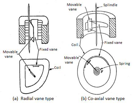
Figure 5. Repulsion type
In repulsion type there are two vanes inside the coil one fixed and the other movable. These are similarly magnetized when the current flows through the coil and there is force of repulsion between the two vanes resulting in the movement of the moving vane.
Key take aways:
The deflecting torque is produced by the electromagnetic action of the current in the coil and the magnetic field. When the torques are balanced the moving coil will stop and its angular deflection represents the amount of electrical current to be measured against a fixed reference, called a scale.
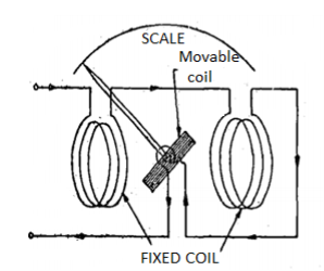
Figure 6. Electrodynamometer
Construction: A fixed coil is divided in to two equal- half. The moving coil is placed between the two- half of the fixed coil. Both the fixed and moving coils are air cored. So that the hysteresis effect will be zero. The pointer is attached with the spindle. In a non- metallic former the moving coil is wounded.
Control: Spring control is used.
Damping: Air friction damping is used.
Principle of operation: When the current flows through the fixed coil, it produced a magnetic field, whose flux density is proportional to the current through the fixed coil. The moving coil is kept in between the fixed coil. When the current passes through the moving coil, a magnetic field is produced by this coil. The magnetic poles are produced in such a way that the torque produced on the moving coil deflects the pointer over the calibrated scale. This instrument works on AC and DC. When AC voltage is applied, alternating current flows through the fixed coil and moving coil. When the current in the fixed coil reverses, the current in the moving coil also reverses. Torque remains in the same direction. Since the current i1 and i2 reverse simultaneously. This is because the fixed and moving coils are either connected in series or parallel.
Torque Equation:
Let i1 = instantaneous value of current in the fixed coils.
i2 = instantaneous value of current in moving coils.
L1 = self-inductance of fixed coils
L2 = self -inductance of moving coils.
M = mutual inductance between fixed and moving coils.
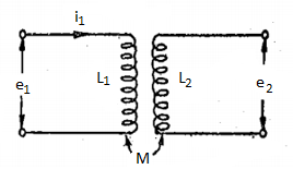
Figure 7. Inductance
Flux linkages of coil 1, λ1= L1i1+ Mi2
Flux linkages of coil 2, λ2 = L2i2+ Mi1
Electrical input energy
e1i1dt + e2i2dt= i1dλ1+i2dλ2
As e1= dλ1/dt and e2=dλ2/dt
= i1d(L1i1+Mi2) +i2d(L2i2+Mi2)
= i1L1di1+i1i2dM+ i12dL1+i1Mdi2+i2L2id2+i2 2 dL2 + i1i2dM+i2Mdi1-----(1)
Energy stored in the magnetic field is = ½ i12 L1 + ½ i2 2 L2 + i1 i2 M
Change in energy stored = d(1/2 i1 2 L1 + ½ i 2 2 L2 + i1 i2 M)
= i1L1di1+(i12/2 ) dL1 + i2L2dI2 + i2 2 /2 dL2 + i1MdI2 + i2 Mdi1 + i1i2dM ---(2)
From principle of conservation of energy,
Total electrical input energy = change in energy stored + mechanical energy
The mechanical energy can be obtained by subtracting (ii) from (1)
Mechanical energy = ½ i12 dL1 + ½ i2 dL2 + i1i2dM
Now the self- inductances L1 and L2 are constants and therefore dL1 are dL2 are both equal to zero.
Hence mechanical energy = i1i2dm
Suppose T1 is the instantaneous deflecting torque and d is the change in deflection then
Work done = Ti d
Thus, we have
Ti d = i1i2dM or Ti= i1i2dM/d
Ammeter
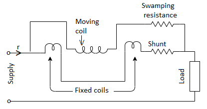
Figure 8. Electrodynamometer
For ammeters of higher capacity the arrangement is shown in figure. The moving coil is connected in series with its swamping resistance across shunt together with fixed coils. Thus there are two separate parallel branches for fixed and moving coils. To indicate correctly at all frequencies the currents in the fixed and moving coils must be in phase. This requires time constant L/R of two branches to be equal otherwise the current in the two branches will not be independent of frequency. This arrangement make L/R ratio equal for both branches.
Voltmeter
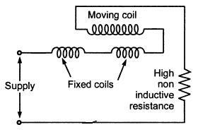
Figure 9. Electrodynamometer voltmeter.
The electrodynamometer movement is used as voltmeter by connecting the fixed and moving coils in series with high non-inductive resistance. The arrangement is shown in figure.
Deflecting torque Td = I1 I2 cos ɸ dM/d
In this case I1 =I2= V/Z and ɸ=0. Td = V/Z .V/Z dM/d
= V 2 / Z 2 dM/d ------------------------(1)
Where V = voltage across the instrument
Z = impedance of the instrument circuit.
Deflection  = V 2 / K Z 2 . DM/d
 .
.
Electrodynamometer type voltmeter is the most accurate type ac voltmeter.
Key Take Aways:
They are used because they have the same calibration for both AC and DC i.e. if it is calibrated with DC, then also without calibrating we can measure AC.
1.6.1 Energy meter Construction
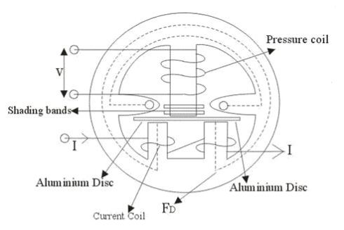
Figure10. Single Phase Energy Meter
There are four main parts of the operating mechanism.
(i) Driving system (ii) Moving system
(ii) Braking system (iv) Registering system
Driving System:
The driving system of the meter consists of two electromagnets. The electromagnets are made up of silicon steel laminations. The coil of the electromagnet is excited by load current. This coil is current coil. The coil of the second electromagnet is connected across the supply and therefore carries current proportional to supply volts. This coil is called pressure coil. These two electromagnets are known as series and shunt magnets respectively.
Copper shading bands are provided on the central limb. The function of these bands to bring the flux produced by the shunt magnet exactly in quadrature with the applied voltage.
Moving System:
It consists of aluminium disc mounted on light alloy shaft. The disc is positioned in the air gap between series and shunt magnets. The moving system floats without touching either bearing surface and the only contact with the movement is that of the gear connecting to the shaft with gear of the train thus the friction is drastically reduced.
Braking System:
A permanent magnet positioned near the edge of the aluminium disc forms the braking system. The aluminium disc moves in the field of this magnet and thus provides a braking torque. The position of permanent magnet is adjustable and therefore braking torque can be adjusted by shifting the permanent magnet to different radial positions.
Registering Mechanism:
The function of registering or counting mechanism is to record continuously a number which is proportional to the revolution made by the moving system.
1.6.2 Wattmeter
Construction
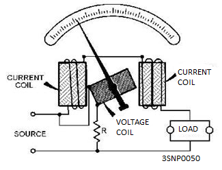
Figure 11. Wattmeter
The internal construction of a wattmeter consists of two cols. One of the coil is in series and the other is connected in parallel. The coil that is connected in series with the circuit is known as the current coil and the one that is connected in parallel with the circuit is known as the voltage coil.
The current of the circuit passes through the current coil and the voltage is dropped across the potential coil as the voltage coil.
The needle that is supposed to move on the marked scale to indicate the amount of power is also attached to the potential coil. The reason for this is that the potential coil can move whereas the current coil is kept fixed.
1.6.3 Theory and Principle of Operation of Electro-Dynamometer
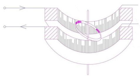
Figure 12. Electrodynamometer Wattmeter
The instantaneous torque of electrodynamometer instruments is given by
Ti = i1 i2 dM/d where i1 and i2 are instantaneous values of currents in two coils. Let V and I be the rms voltage and current being measured.
Instantaneous value of the voltage across the pressure coil circuit
v = √2 V sin wt
If the pressure coil circuit has very high resistance it can be treated as purely resistive. Therefore, current ip in the pressure coil is in phase with the voltage and its instantaneous value is
Ip = v/Rp = √2 V/Rp sin wt = √2 Ip sin wt
Here Ip = Vp/Rp = rms value of current in pressure coil circuit and Rs = resistance of pressure coil circuit.
If the current in the current coil lags the voltage in phase by an angle ɸ the instantaneous value of current through current coil is:
Ie = √2 I sin(wt -ɸ)
Instantaneous torque Ti = √2 Ip sin wt x √ 2 I sin (wt -ɸ) dM/d
= 2Ip I sin wt sin(wt -ɸ) dM/d = Ip I[ cos ɸ - cos(2wt-ɸ)] dM/d
 -----(1)
There is a component of power which varies as twice the frequency of the current and voltage
Td = 1/T  d(wt) = 1/T
  I[ cos ɸ - cos(2wt-ɸ) ] dM/d
 . d(wt)
= Ip I cos ɸ dM/d ----------------------------------(2)
= VI/Rp cos ɸ dM/d ------------------------------------------(3)
Controlling torque exerted by springs Ts = K
K=spring constant  = final steady deflection
Since the moving system of the instrument cannot follow the rapid variations in torque it will take up a position at which the average deflection torque is equal to the restoring torque of the springs.
At balance position K = Ip I cos ɸ dM/d
 ---------------------(4)
Or deflection  = Ip/K I cos ɸ.dM/d
 …………………………..(5)
= VI cos ɸ/ Rp K . DM /d -------------------------------------------(6)
= K1VI cos ɸ. DM /d ----------------------------------------------------(7)
= (K1 dM/d ) P --------------------------------------------------(8)
P=power being measured = VI cos ɸ
And K1 = 1/Rp K ---------------------------------------------(9)
1.6.4 Theory and Principle of Operation of Induction type Wattmeter
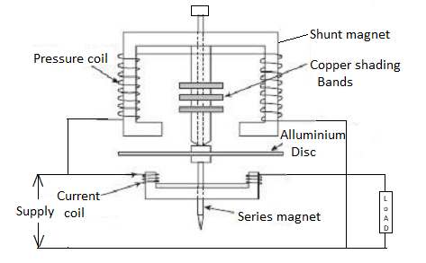
Figure 13. Induction type Wattmeter
Principle of Operation:
The shunt and series magnets produce alternating fluxes. These fluxes produce eddy emfs in disc and in turn cause eddy currents to flow. These eddy currents interact with the fluxes to produce deflecting torque.
Theory:
The theory and operation of induction type wattmeter is similar to that of an induction type wattmeter. The only difference is that in induction wattmeter a control spring restricts the motion of the disc by exerting a controlling torque while an induction watthour energy meter the disc is allowed to rotate continuously.
Deflecting torque Td = K1VI cos ɸ = K1 P
Where P=VI cos ɸ = power in the circuit
Controlling torque Tc = K 
Deflection  = K1/K P = K’ VI cos ɸ where K1 and K’ are constants.
A 240 volt, 5 ampere, single phase energy meter has a constant of 1200 revolutions per kilo watt hour (KWh). When tested by applying 240 volts, the meter took 99.8 seconds to complete 40 revolutions. Find the percentage error. Is it running fast or slow ?
Solution: The total energy consumed = V I t (cos ϕ) Wh i.e., TREnergy = [ (240) (5) (99.8 / 3600) (1.0) ] = 33.2667 Wh. The indicated reading, IREnergy = revolutions made / kE in rev./ KWh = ( 40 / 1200 ) 103 = 33.3333 Wh.
Thus, energy error = TREnergy – IREnergy = 33.2667 – 33.3333
Percentage error = (- 0.0666 / 33.2667 ) 100 % = - 0.2 % .
Since the energy recorded is more, the energy meter is running fast under the given operating conditions.
Key Take Aways:
The instrument whose working depends on the reaction between the magnetic field of moving and fixed coils is known as the Electrodynamo-meter Wattmeter.
1.6.5 Compensation, creep, error testing
In some energy meters, when the pressure coil is energized, a slow, but continuous rotation of the disc is observed even when there is no current in the current coil. This is called creeping.
Compensation is a technique used to compensate for error added during measurement.
Error testing:
Earth currents can be prevented or reduced by interrupting the ground loop. This is possible by using equipment like power supplies, signal generators, etc. whose inputs and/or outputs are isolated from the earth connection.
Key Take Aways:
Different observations in energy meter.
Single phase Induction type watt-hour meter
Single phase induction type energy meter consists of four important systems which are written as follows:
Driving System:
Driving system consists of two electromagnets on which pressure coil and current coils are wounded, as shown in the diagram.
The coil which consisted of load current is called current coil while coil which is in parallel with the supply voltage is called pressure coil. Shading bands are wounded on as shown above in the diagram to make angle between flux and applied voltage equal to 90 degrees.
Moving System:
To reduce friction to greater extent floating shaft energy meter is used, the friction is reduced to greater extinct because the rotating disc which is made up of light material like aluminium is not in contact with any of the surface. It floats in the air.
Braking System:
A permanent magnet is used to produce breaking torque in single phase induction energy meters which are positioned near the corner of the aluminium disc.
Counting System:
Numbers marked on the meter are proportion to the revolutions made by the aluminium disc, the main function of this system is to record the number of revolutions made by the aluminium disc.
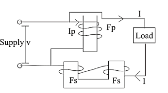
Figure 14. Single Phase Induction Meter
The pressure coil is highly inductive in nature and consists of large number of turns. The current flowing in the pressure coil is Ip which lags voltage by an angle of 90 degrees. This current produce flux F. F is divided into two parts Fg and Fp.
Polyphase Induction type watt-hour
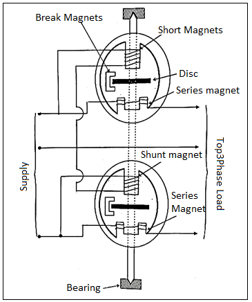
Figure 15. Polyphase Induction Energy Meter
A two-element energy meter used for measurement of energy in 3-phase, 3- wire circuit.
It consists of two discs mounted on common spindle. The moving system drives a single gear train. Each unit is provided with its own shading ring, shading bands and break magnet for adjustments.
It is essential that the driving torque of two elements be the same for the same power passing through them. This condition is checked by energizing the coils from a single circuit, the two pressure coils being connected in parallel and the circuit coils in series, with one reversed to oppose the other. This arrangement causes the two torques to be in opposition and if the two torques are equal, the disc will not rotate.
Key Take Aways:
The meter which is used for measuring the energy utilises by the electric load is known as the energy meter. The energy is the total power consumed and utilised by the load at a particular interval of time.
1.8.1 Vibrating reed type
Construction:
This meter consists of several thin steels called reeds. These reeds are placed in arow alongside and close to an electromagnet as shown in figure. The electromagnet has a laminated iron core, and its coil is connected in series with the resistance across the supply whose frequency is to be measured.
The natural frequency of the reeds depends on the weights and dimensions. Since the reeds have different weight and size their natural frequency of vibration are different.
Operation:
When the frequency meter is connected across the supply whose frequency is to be measured the coil of electromagnet carries I which alternates at the supply frequency. The force of attraction between the reeds and the electromagnet is proportional to i2 and therefore this force varies twice the supply frequency.
Thus, the force is exerted on the reeds every half cycle. All the reeds will tend to vibrate but the reed whose natural frequency is equal to twice the frequency of supply will be in resonance and vibrate the most. The tuning in these meters is so sharp that as the excitation frequency departs from the resonant frequency the amplitude of vibration decreases rapidly becoming negligible.
When the 50Hz reed is vibrating with maximum amplitude some vibrations of 49.5 Hz and 50.5 Hz reeds in fig(b). For frequency midway between the reeds will vibrate with amplitudes which are equal in magnitude. Fig(c) shows the condition of vibrating reeds when the frequency is exactly midway between 49.5Hz and 50Hz.
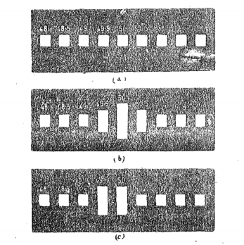
Figure 16. Indication of vibrating reeds.
1.8.2 Electrical resonance type
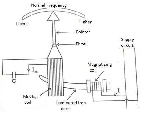
Figure 17. Electrical resonance type
It consists of fixed coil which is connected across the supply whose frequency is to be measured. This coil is called magnetizing coil. The magnetizing coil is mounted on laminated iron core. The iron core has cross-section which varies gradually over length being maximum near the end where the magnetizing coil is mounted and minimum at the other end. A moving coil is pivoted over this iron core. A pointer is attached to the moving coil. The terminals of the moving coil are connected to suitable capacitor C. There is no controlling force.
The operation of the instrument can be understood from three phasor diagrams (a),(b),(c). The magnetizing coil carries current I and this current produces flux ɸ. Flux ɸ being alternating in nature induces emf e in the moving coil. This emf lags behind the flux by 90. The emf induced circulates current I in the moving coil. The phase of this current I depends on L and capacitance.

Figure 18. Phasor diagram for electrical resonance
In fig(a) the circuit of the moving coil is assumed to be inductive and therefore current I lags behind emf e by angle α. The torque acting on the moving coil is
Td α Ii cos(90+α)
In fig(b) the moving coil is assumed to be capacitive and therefore current I leads emf by angle β and the deflecting torque is
Td α Ii cos(90-β)
In fig (c ) the inductive reactance is supposed to be equal to capacitive reactance therefore the circuit is in resonance. Thus the moving coil circuit is purely resistive and so the current I is phase with emf e. This is because inductive reactance XL = 2 πfL =Xc= 1/2πfC . Therefore the net reactance of the circuit is zero.
The deflecting torque is therefore
Td α Ii cos 90 =0
Hence the deflecting torque on the moving coil is zero when the inductive reactance equals capacitive reactance.
Power factor meters
The power factor meter measures the power factor of a transmission system. The power factor is the cosine of the angle between the voltage and current.
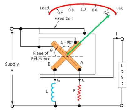
Figure 19. Single phase Electrodynamometer Power meter
The construction of the single -phase electrodynamometer is shown in the figure below. The meter has fixed coil which acts as a current coil. This coil is split into two parts and carry the current under test. The magnetic field of the coil is directly proportional to the current flow through the coil.
The meter has two identical pressure coils A and B. Both the coils are pivoted on the spindle. The pressure coil A has no inductive resistance connected in series with the circuit, and the coil B has highly inductive coil connected in series with the circuit.
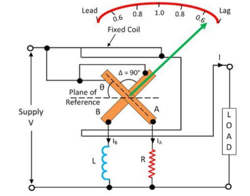
Figure 20. Pressure Coils
The current in the coil A is in phase with the circuit while the current in the coil B lag by the voltage nearly equal to 90º. The connection of the moving coil is made through silver or gold ligaments which minimize the controlling torque of the moving system.
The meter has two deflecting torque one acting on the coil A, and the other is on coil B. The windings are so arranged that they are opposite in directions. The pointer is in equilibrium when the torques are equal.
Deflecting torque acting on the coil A is given as
TA = KVIM cosɸ sin 
θ – angular deflection from the plane of reference.
Mmax – maximum value of mutual inductance between the coils.
The deflecting torque acting on coil B is expressed as
IB = KVIMmax cos(90-ɸ) sin (90+ɸ)
IB = KVIMmax cos ɸ sin 
The deflecting torque is acting on the clockwise direction.
The value of maximum mutual inductance is same between both the deflecting equations.
TA = TB
KVIM cosɸ sin  = KVIMmax cos ɸ sin
This torque acts on anti-clockwise direction. The above equation shows that the deflecting torque is equal to the phase angle of the circuit.
Key Take Aways:
A frequency meter is an instrument that displays the frequency of a periodic electrical signal.
References:
- Elements of Electronic Instrumentation and Measurement – by Carr
- Basic Electrical, Electronics and Measurement Engineering Paperback – 1 January 2019 by U.A Bakshi and A.P Godse.
- Electrical and Electronic Measurement and Instrument Paperback R.K Rajput
- Electrical & Electronic Measurements B. P. Patil, Pooja Mogre (Bisen)
- Electronic Measurements and Instrumentation By A.K. Sawhney