Unit - 3
Transmission systems
It is the mechanism which transmits the power to the driving wheels which is developed by the engine of an automobile. It is also called Power Train. It constitutes:
• Tyres
• Propeller shaft
• The gear box
• Wheel
• Rear axle
• Universal joints
• Clutch
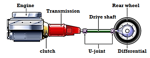
Fig 1 Components of Transmission system.
Requirements: -
• It can sustain the consequence of torque forces, driving thrust and braking force efficiently.
• It provides means to drive the driving wheels at dissimilar velocities when necessary.
• It enables flow of power at 90 (right) angles.
• It must enable transmission of power at different angles and lengths.
• It enables speed reduction between engine and the drive wheels in the ratio of 5:1.
• It offers ways to transmit power in opposed direction.
• It provides a varied leverage between the engine and the drive wheels
• It offers linking and de-linking of engine with other members of power train effortlessly and devoid of shock.
The main units of the transmission system according to the above requirements are as follow:
• Clutch
• Propeller Shaft and Universal Joints.
• Gear Box
• Transfer Case
• Final Drive
• Differential
• Torque Tube
• Road Wheel
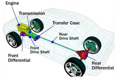
Fig 2 Main units of Transmission System.
Key Takeaways:
• It is the mechanism which transmits the power to the driving wheels which is developed by the engine of an automobile.
• It enables flow of power at 90 (right) angles.
• It offers linking and de-linking of engine with other members of power train effortlessly and devoid of shock.
- In phrases of mechanical engineering, a grab is that sort of tool which utilized by engineers to interact in addition to disengage transmission of electricity from a using shaft to a pushed shaft.
- In the mechanism of a grab, the using shaft is without delay linked to an engine while the alternative one or the pushed shaft offers the electricity output this is used by the consumer for working.
- Often instances clutches are used to restriction the movement or quantity of electricity transmission among components.
- A not unusual place instance of a grab is that it's far utilized in cars for enticing in addition to disengaging gearbox and the engine of the automobile.
Types of Clutches:
In mechanical engineering distinct sorts of clutches are present. Numerous sorts of clutches are utilized in a couple of functions through engineers, despite the fact that each kind has it is.
The running precept of various sorts of clutches is likewise distinct in nature this is why on this segment of this assessment, distinct sorts of clutches are mentioned in brief to offer an in depth view.
- Friction Clutch
- Single Plate Clutch
- Multi Plate Clutch
- Cone Clutch
- Centrifugal Clutch
- Semi-centrifugal Clutch
- Diaphragm Clutch
- Dog and Spline Clutch
- Electromagnetic Clutch
- Vacuum Clutches
- Hydraulic clutch
- Freewheel Clutch
Cone Clutch is a type of frictional capture. It is used to engage and disengage engine shaft to the transmission discipline shaft even as changing equipment ratio. Cone capture makes use of conical surfaces to transmit torque with the useful resource of the use of friction.
Cone capture is much less complex to engage and disengage in comparison to a pleasant displacement capture which modified into used in advance than cone clutches have been invented. Higher torque can be transferred using the cone capture than same period of plate capture due to greater contact area. The driving shaft and the driven shaft want to be perfectly coaxial for inexperienced functioning of the capture. This capture can be used wherein immoderate torque transmission is wanted at low rotating speed. So, this type of capture is extensively is heavy vehicles.
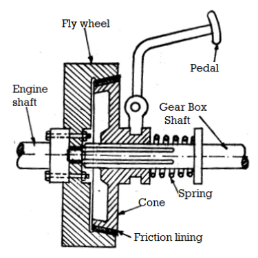
Fig 3. Cone Clutch
Parts of Cone Clutch:
1. Female Cone or Outer Cone:
It is the part of the cone grasp this is linked to the flywheel of the engine and additionally rotates with it. This component identity notification continually in rotating circumstance because the engine shaft rotates continuously. Female cone has internal slicing cone-fashioned groove which has friction lining over which the male cone interlocks and make frictional touch with it in an effort to have interaction the drive. This lady cone is installed over stable shaft.
2. Male Cone or Inner Cone:
This cone is hooked up to the transmission device or the gearbox. Inner cone has friction lining with inside the outer component which creates frictional touch with internal friction lining of the outer cone. By default, internal cone stays in touch with the outer cone with the assist of strain springs that is located at the back of the internal cone. When the grasp pedal is pressed in situations like converting gear, the spring is compressed and the internal cone actions far from the outer cone and disengages from the outer cone and consequently the engine is disengaged from the transmission box. This internal cone has internal splines and actions over slices of shaft for to and from motion.
3. Springs:
Springs are positioned in the back of the male cone which can be used to hold the internal cone engaged with outer cone. When the seize pedal is pressed, the spring compresses and the internal cone disengages with outer cone and consequently the driving shaft is disconnected from pushed shaft.
4. Sleeves:
Sleeves are the part of the seize that is connected to the male cone and installed at the splines and those sleeves are used for back and forth movement of male cone.
5. Pedal:
A seize pedal is used to function the seize.
Working:
By default, the male cone is engaged with the woman cone because of the strain of the spring that's gift at the back of the male cone. When the take hold of pedal is pressed so that it will extrude the tools or for a few different cause, the fulcrum that's connected to pedal rotates which in flip compresses the spring and additionally the male cone is pulled far from the woman cone. Thus the touch among the male cone and woman cone will break.
So, the engine shaft may be disengaged from transmission device and rotation of engine shaft or using shaft will now no longer be transferred to the transmission shaft or the pushed shaft. Now after the disengagement whilst the take hold of pedal is launched slowly with the aid of using the motive force after converting the gears, the fulcrum that's connected to the pedal rotates and the spring expands and the male cone begins off evolved transferring closer to the woman cone over splines.
After that, the male take hold of make touch with the woman take hold of and friction pressure act among the internal friction lining of outer cone and outer friction lining of internal cone. Now the cone take hold of is stated to be in have interaction role and the rotation of engine shaft or using shaft is transferred to the transmission shaft or pushed shaft and each the shaft begin rotating at equal speed. The stiffness with the aid of using the spring continues the male cone and woman cone of the cone take hold of in engaged role.
Advantages:
1) The ordinary pressure performing on touch floor is more than the axial pressure.
2) Higher torque may be transferred than the identical length of plate grab because of huge quantity of frictional pressure involved.
3) It creates much less noise than plate grab.
4) Less put on and tear compared to displacement grab.
Key Takeaways:
• Cone capture makes use of conical surfaces to transmit torque with the useful resource of the use of friction.
• It is the part of the cone grasp this is linked to the flywheel of the engine and additionally rotates with it.
• By default, the male cone is engaged with the woman cone because of the strain of the spring that's gift at the back of the male cone.
Single Plate Clutch (SPC)
- The diagram of SPC is given below in Fig. 4, with the friction plate placed between the flywheel and the pressure plate.
- Springs are provided tangentially offering axial force keeping the clutch in the engaged position.
- The second friction plate is attached on a hub (split from the inside) and thus the gear box is free to slide on the shaft. Friction is encountered from the friction plate on either side to provide two annular friction surfaces for the transmission of power.
- Clutch pedal is also there which pulls the pressure plate against the spring force every time detachment is required. It usually continues to be in engaged position (Figure 4).
- As the pedal is depressed, the pressure plate moves to the right opposite to spring force. This is achieved through a suitable linkage (not shown in Figure 4) and a thrust bearing. As such, the friction plate and clutch are released.
- In real sense, the clutch construction varies. The plate (pressure), springs, releasing lever and cover forms a cover assembly, that can be fixed straightly to the engine block, with the clutch plate placed between the flywheel and the pressure plate.
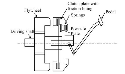
Fig 4 Single Plate Clutch.
Key Takeaways:
- Springs are provided tangentially offering axial force keeping the clutch in the engaged position.
- As the pedal is depressed, the pressure plate moves to the right opposite to spring force.
Multiplate Clutch (MPC)
- This type of clutch is a modified version of SPC where friction and number of metallic plates are increased.
- Due to growth of frictional surfaces, the ability of the clutch to transmit torque increases.
- The overall diameter of the clutch is reduced for torque transmission similar to a single plate clutch. Hence, MPC is applicable where high torque transmission is required like various heavy automobiles and racing cars.
- This is also used in scooters and motorcycles, due to space limitation.
- The framework is comparable to the SPC, exception being that, the friction plates are in 2 pairs, i.e., one pair of plates slips into the groove on the flywheel and the other a pressure plate slides onto the hub splines. Alternative plates belong to each set.
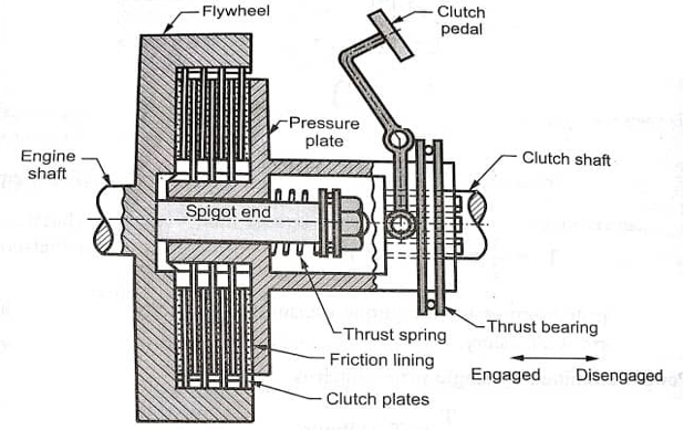
Fig 5 Multiplate Clutch
Working of MPC is divided into 2 steps as discussed below:
Engagement
- As the paddle is pressed, the engagement takes place in the engine and the movements of the thrust springs is enhanced.
- Thrust springs offers pressure to the pressure plates making the pressure plate to move in forward direction.
- Also, the linings which are placed on the inner side of the pressure plate make contact with the flywheel, start its action.
- Consequently, the clutch engages.
Disengagement
- For disengagement of engine and clutch, the clutch pedals as well as the fins of inner splined sleeves are pressed.
- Thrust spring moves in backward direction releasing pressure from the pressure plates and plate also moves backward.
- Consequently, due to released pressure from the flywheel, plate and springs the clutch disengages.
Key Takeaways:
- This type of clutch is a modified version of SPC where friction and number of metallic plates are increased.
- The overall diameter of the clutch is reduced for torque transmission similar to a single plate clutch.
- Thrust springs offers pressure to the pressure plates making the pressure plate to move in forward direction.
Diaphragm Spring:
Eaton gives an extensive kind of diaphragm spring clutches to match pretty much any business automobile application. Built to strict OEM best standards, they make sure first-rate overall performance and grab existence. Their strong and easy walking layout reduces idling noise and might notably lessen extreme vibrations, extending drivetrain thing existence and the sturdiness of transmission synchronizers.
Working:
Figure indicates the development information of the diaphragm take hold of. It includes a diaphragm spring that is supported on a fulcrum preserving ring i.e. pivot ring in order that any phase thru the spring may be appeared as a easy lever. In the engaged role, the spring pivots at the rear pivot jewellery as it's far held in a take hold of cowl in order that its outer rim contacts the stress plate.
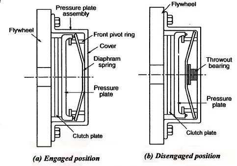
Fig 6. Diaphragm clutch
Therefore, enough stress is exerted with the aid of using the spring creating a company touch among stress plate and take hold of plate in addition to the flywheel in its herbal conical role. To disengage the take hold of, the pedal is depressed to purpose the linkage to transport throw-out bearing toward the flywheel. As the bearing contacts the internal role of the conical spring, it movements ahead which reasons the rim to transport backward because the spring pivots at the front pivot ring. It eliminates the stress at the stress plate and releases the take hold of disc from touch with each using members.
Features:
- Available in plenty of sizes from 280 millimeters to 430 millimeters
- Engineered and synthetic to unique gadget specifications
- Single or dual plate designs
- Soft-price dampers assist defend in opposition to dangerous torsional vibrations and growth the sturdiness of transmission synchronizers and driveline components
- Smooth engagement and much less pedal effort Available pre-dampers cast off rattle at idle
Centrifugal Clutch:
Centrifugal Clutch is a kind of grasp wherein centrifugal pressure is used to attach the engine pressure shaft with the shaft of the transmission. It is located in among the engine flywheel and the transmission system. Its important feature is to attach the engine shaft with the transmission shaft. It works extra successfully at better speeds.
Parts of centrifugal clutch:
- Shoes:
It includes friction lining on the stop and this friction lining makes touch with the drum for the duration of the engagement.
2. Spring:
Spring is used to disengage the snatch while the engine rotates at a slower speed.
3. Spider or publications:
The spiders are established at the driver (engine) shaft or motor shaft. The spiders are similarly spaced. Equally spaced means, if they may be 4 publications than every manual is separated from every different through ninety degree. The sliding footwear are saved in among those publications and every manual is maintaining a spring.
4. Friction lining:
The outer floor of sliding footwear has friction lining. It allows in creating a grip with the internal floor of the drum.
5. Drum:
The drum of the snatch act as housing which encloses all of the components of the snatch that consists of sliding footwear, publications, springs etc. It is attached to the pushed shaft of the transmission gadget or chains or belt.
Working:
- As the engine rotates, the interior meeting of the centrifugal snatch begins off evolved rotating however drum stays desk bound and no electricity is transmitted.
- At decrease pace, the centrifugal pressure produced isn't enough to triumph over the spring pressure. So the snatch stays disengaged. But as the velocity will increase, the centrifugal pressure additionally will increase and now the centrifugal pressure will become more than the spring pressure.
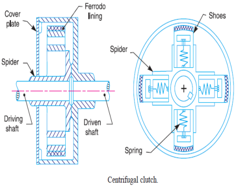
Fig 7. Centrifugal Clutch
- As the centrifugal pressure will become more than the spring pressure, this lets in the sliding footwear to transport outward in opposition to the spring and get engaged with the internal floor of the drum.
- The drum begins off evolved rotating and transfers the rotating electricity from the engine to the pushed shaft of the transmission. When the burden at the engine will increase, its pace decreases and disengages the snatch.
Key Takeaways:
- It eliminates the stress at the stress plate and releases the take hold of disc from touch with each using members.
- Available in plenty of sizes from 280 millimeters to 430 millimeters
- To disengage the take hold of, the pedal is depressed to purpose the linkage to transport throw-out bearing toward the flywheel.
- Spring is used to disengage the snatch while the engine rotates at a slower speed.
- It is attached to the pushed shaft of the transmission gadget or chains or belt.
- The working precept of the actuator of electromagnetic snatch is an electromagnetic effect, however torque transmission is mechanical.
- The distinction among electromagnetic snatch and the everyday snatch is in how they manipulate the motion of strain plates.
- In the ordinary snatch, a spring used to interact the snatch while in EM snatch an electromagnetic area is used for engagement.
- The electromagnetic snatch comes numerous forms, such as magnetic particle snatch and multi-disc snatch.
- There are even no-touch clutches which include hysteresis snatch and eddy cutting-edge snatch. However, maximum broadly used shape is unmarried face friction snatch.
Construction:
Rotor:
Rotor is a primary a part of this snatch witch is hooked up at once to the riding shaft or engine shaft. It constantly rotate alongside the riding shaft.
Winding or Coil:
Winding coil is located at the back of the rotor and stays in desk bound function for the duration of snatch working. It is proven in figure. A excessive voltage DC deliver is hooked up with this winding which switch a excessive voltage present day into this winding and convert it into electromagnet.
Armature:
Armature is located at the front of the rotor. It is hooked up to the hub or stress plated with the assist or rivet or bolted joint.
Hub:
Hub or stress plate is bolted with the tools shaft or pushed shaft and rotates with it. It is located after the armature.
Friction Plate:
Friction plate is inserted among armature and rotor in keeping with the requirement.
Supply unit:
Supply unit consist snatch switch, battery, cord etc.
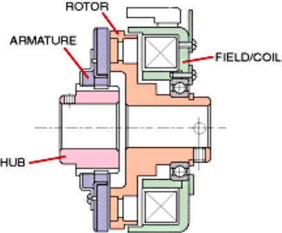
Fig 8: Electromagnetic Clutch
Working of electromagnetic clutch
- The predominant additives of EM take hold of are a coil shell, an armature, rotor, and hub.
- The armature plate is covered with friction coating. The coil is positioned at the back of the rotor.
- When the take hold of activated the electrical circuit energizes the coil, it generates a magnetic area. The rotor part of take hold of receives magnetized.
- When the magnetic area exceeds the air hole among rotor and armature after which it pulls the armature towards the rotor. The frictional pressure generated on the touch floor switch the torque.
- Engagement time relies upon at the electricity of magnetic fields, inertia, and air hole. When voltage is eliminated from the coil, the touch is gone.
Key Takeaways:
- The electromagnetic snatch comes numerous forms, such as magnetic particle snatch and multi-disc snatch.
- Friction plate is inserted among armature and rotor in keeping with the requirement.
- The frictional pressure generated on the touch floor switch the torque.
The factor is this mechanism is designed to extrude the wheel revolution quantity on the equal engine rotation rate. All internal-combustion engines have a quick operating frequency variety and their strength is pretty low. For instance, a widespread engine version offers round 800-5000 revolutions consistent with minute. During the motion of cars, this variety narrows from 1500 to 4000 revolutions consistent with minute. If you preserve the low quantity of revolutions (much less than 1500), then the device will speedy devour all lubricating oils and could surely wreck down. But, in case you power at excessive revolutions, then there may be a danger of the speedy element wear, and with inside the end, you ought to lay your vehicle up for maintenance or update its engine. This trouble is removed with the aid of using the principle characteristic of equipment box.
Manual Gear Shift Mechanism:
A guide transmission offers you a opportunity to shift gears manually. It consists of moving mechanism, synchronizers, intermediate, enter and output shafts, auxiliary shaft, casing and opposite equipment. The majority of gearboxes of this kind have 4 or 5 gears and one opposite.
As for the relaxation of advantages, right here they are: This kind stands proud for its enviable existence cycle. A guide transmission may even out survive the existence of the automobile’s engine.
- Excellent fuelling mileage.
- When in comparison with an automated transmission, the automobile with the guide one consumes 15% much less gasoline and has better acceleration dynamics.
- High efficiency – a guide transmission makes it viable to apply all to be had torque-wearing capacity.
- Good vehicle behaviour – you could adjust the equipment moving system with the aid of using your own, deciding on the maximum snug using style. Low weight (decrease than that of an automated transmission).
- Possibility to begin up the engine regardless of the discharged battery and low-appearing ignition.
Possibility to tow a vehicle each via inflexible and bendy towline. Speaking approximately its disadvantages, it ought to be cited that the exploitation of forms of guide transmission may be pretty tough for beginners. A driving force will must use it in tandem with the clutch, so there may be a massive risk to disrupt it with the aid of using creating a rookie mistake. On pinnacle of that, in case you forgot to shift equipment, it is able to motive a few engine lug. Another component is that town using will make you shift gears manually all of the time.
Automatic Gear Shift Mechanism:
The production of all automated equipment bins is a long way extra complicated than that of guide ones. It includes extra gadgets and parts, so its purchase, installation, exploitation and restore don’t come cheap.
But this transmission is higher suitable for metropolis driving. It is exceedingly desired with the aid of using beginners, on the grounds that this form of gearbox in vehicle eliminates the need to tug the lever and use the seize all of the time.
The equipment pump is located among the planetary gear set and torque converter, wherein it pulls and pressurizer’s transmission fluid from a sump.
The pump enter leads at once to the housing of the torque converter connected to the flex plate of the engine. When the engine isn't always running, the transmission does now no longer have the oil strain had to function and as a result the car cannot be push-started.
The planetary equipment educate is a mechanical device wherein the gears are related with a hard and fast of bands and clutches.
When the driving force modifications gears, the bands maintain one equipment nonetheless at the same time as rotating some other to transmit torque from the engine and boom or lower gears.
Key Takeaways:
- For instance, a widespread engine version offers round 800-5000 revolutions consistent with minute.
- Possibility to tow a vehicle each via inflexible and bendy towline.
- The production of all automated equipment bins is a long way extra complicated than that of guide ones.
- The pump enter leads at once to the housing of the torque converter connected to the flex plate of the engine.
The tool this is used to boom the velocity of the wheel more than the engine velocity that's located in among the Transmission gadget and the Propeller shaft known as Overdrive in Automobile.
As Overdrive is a gadget that may be located after the Gearbox, we want to understand a chunk approximately the few additives of the Transmission System which had been indexed below.
Working Principle of Overdrive in Automobile:
- The overdrive is to be positioned in among the Gearbox and the Propeller shaft. The characteristic of overdrive is to growth extra quantity of energy than the energy added from the gearbox. On the enter shaft, the Sun equipment is hooked up via Spline.
- The freewheel has an inner spline and the Input shaft has an outside Spline and those will mesh together. Whenever there may be a spline joint, the Freewheel does now no longer go through any rotary relative movement however it has handiest horizontal relative movement.
- In the sense, the Freewheel can circulate handiest with inside the horizontal route however cannot rotate on the middle of the enter shaft. Whereas the solar equipment is freely established at the enter shaft.
- It method that, every time the shaft is rotating, the Sun Gear can also additionally or might not rotate however the Freewheel has to transport w.r.t. The enter shaft handiest. The Sun Gear meshes with the planet gears and this planet gears are in touch with the Planet Carrier.
- The Planet Gear is likewise in touch with the hoop equipment and from the hoop equipment, the energy is despatched to the output shaft.
Advantages of Overdrive in Automobile:
- At cruising speed, it may efficiently transfer the engine's power to the road wheels.
Disadvantages of Overdrive in Automobile:
- If you want to overtake a vehicle, then the usage of overdrive is a horrible idea.
- If you are going off-avenue or mountain climbing a hill then you definitely want to now not use Overdrive.
Applications of Overdrive in Automobile:
- It is basically applied in Racing Cars
Key Takeaways:
- The Transmission gadget and the Propeller shaft known as Overdrive in Automobile.
- The overdrive is to be positioned in among the Gearbox and the Propeller shaft.
- In the sense, the Freewheel can circulate handiest with inside the horizontal route however cannot rotate on the middle of the enter shaft.
Transfer container is part of a 4-wheel-power device utilized in 4-wheel-power or all-wheel power vehicles. It is likewise referred to as “switch equipment case”, “switch gearbox”, “switch container”, ‘jockey container” or “T-case”. The feature of switch container is to distribute the torque generated in engine to all 4 wheels of the automobile.
The switch container is hooked up to the engine, the front axles and rear axles thru power shafts. The switch equipment container is managed via way of means of the driver. The manipulate is placed with inside the automobile compartment. It is both with inside the shape of a switch lever or a button.
Construction of Transfer Box:
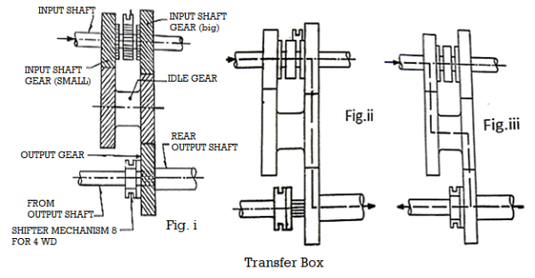
- The enter shaft is attached to the tools container and consists of on it a member having axial tooth.
- Two enter shaft gears are unfastened to rotate at the shaft. Each of those gears have bosses at the fact that have axial tooth of the identical pitch because the imperative member at the enter shaft.
- Depending upon the motion of the switch container tools lever, the imperative member and thereby the enter shaft can be linked both to the small tools and to the large tools.
- There are output shafts, one going to the front axle and the second one going to the rear axle.
- The front output shaft has geared up on it a shifter mechanism and additionally has splines over a small duration of it, which while have interaction with the corresponding inner splines at the rear output shaft, join the 2 shafts rotationally with every other.
Working Of Transfer Box:
When the shifter mechanism A is with inside the centre in order that no tools is attached to the enter shaft, the power is in impartial as proven in Fig.i. Fig. Ii suggests whilst the shifter mechanism A connects the enter shaft with the large enter tools, however the shifter mechanism B disconnects the front output of shaft from the rear output shaft.
In this position, two-wheel power with the excessive tools is obtained. In the identical manner Fig. Iii depicts the state of affairs with 4 wheel power in low.
Key Takeaways:
- The feature of switch container is to distribute the torque generated in engine to all 4 wheels of the automobile.
- There are output shafts, one going to the front axle and the second one going to the rear axle.
- The switch container is hooked up to the engine, the front axles and rear axles thru power shafts.
- The transaxle may be orientated both transversely and longitudinally. The transverse axles are utilized in live performance with the transverse engines in lots of cutting-edge the front-wheel pressure cars.
- This is a configuration that locations the whole pressure teach in addition to the pressure wheels on the front quit of the car. On the alternative hand, a whole lot of the rear-wheel-pressure cars additionally use the longitudinal engine geared up with a traditional transmission in addition to a drivetrain. However, on this sort of set-up, they both have a mid or rear-engine set-up.
- When the engine is installation on the rear, the whole configuration is pretty much like the only on an FWD vehicle.
- Also, there are numerous approaches to strengthen the power of transmission rather than the usage of a transaxle. While in principle there exists transaxles designs that would take care of ultra-effective engine designs, their compact nature poses a few extreme engineering challenges.
- Transmissions, on the alternative hand, have greater room for cautious design. Moreover, the separate rear differential way that you can effortlessly switch it out for an upgraded one. There additionally exists rear-wheel drive (RWD) cars that include transaxles too. Instead of becoming beside the engine, the transaxle is located with inside the rear wherein the rear differential desires to be.
- It isn’t normal, however it enables in higher weight distribution disposing of the want for a rear differential as well. Generally, transaxles will now no longer include guide transmission because of the manner they may be packaged, and could nearly continually be automatic.
Key Takeaways:
- The transaxle may be orientated both transversely and longitudinally.
- This is a configuration that locations the whole pressure teach in addition to the pressure wheels on the front quit of the car.
- There additionally exists rear-wheel drive (RWD) cars that include transaxles too.
A flywheel is a mechanical tool which makes use of the conservation of angular momentum to keep rotational electricity; a shape of kinetic electricity proportional to the made of its second of inertia and the rectangular of its rotational speed.
In particular, if we expect the flywheel's second of inertia to be constant (i.e., a flywheel with constant mass and 2nd second of place revolving approximately a few constant axis) then the saved (rotational) electricity is immediately related to the rectangular of its rotational speed.
Since a flywheel serves to keep mechanical electricity for later use, it's miles herbal to recollect it as a kinetic electricity analogue of an electrical inductor. Once certainly abstracted, this shared precept of electricity garage is defined with inside the generalized idea of an accumulator.
As with different kinds of accumulators, a flywheel inherently smoothest small enough deviations with inside the electricity output of a system, thereby correctly gambling the function of a low-by skip clear out with admire to the mechanical velocity (angular, or otherwise) of the system.
More precisely, a flywheel's saved electricity will donate a surge in electricity output upon a drop in electricity enter and could conversely soak up any extra electricity enter (system-generated electricity) with inside the shape of rotational electricity.
Common uses of a flywheel include:
- Smoothing the energy output of an energy source.
- For example, flywheels are applied in reciprocating engines because of the truth the active torque from the man or woman pistons is intermittent.
- This is finished thru manner of method of amassing energy in a flywheel over time and then releasing it quickly, at expenses that exceed the abilities of the energy source.
- Controlling the orientation of a mechanical system, gyroscope and reaction wheel
Key Takeaways:
- Since a flywheel serves to keep mechanical electricity for later use, it's miles herbal to recollect it as a kinetic electricity analogue of an electrical inductor.
- Smoothing the energy output of an energy source.
• This is a hydraulic transmission drive which is used to increase the torque of the automobile and henceforth reducing its speed.
• Torque converter provides constant deviation in the ratio of low to high.
• The important feature of this device is its capability to double (multiply) torque when there is a noticeable difference b/w the I/P and O/P rotational speeds comparable to a reduction gear.
• Cars working on automatic transmission have no clutch for disconnecting the transmission from the engine. As such they use this device.
Working
- As the engine switches on, rotation of the impeller starts. High centrifugal forces are generated inside the impellor which forces the oil (hydraulic fluid) into the turbine, turbine is still motionless.
- The hydraulic fluid thus gains high kinetic energy from the engine and knocks the external edges of the turbine. The force of high KE fluid (oil) causes the turbine to rotate. This force gets increased as the engine speed increase.
- When this force become very high, the turbine starts rotating in fruitful manner and the automobile starts moving.
- The turbine blade angle is such that it changes the direction of oil flow so that when it comes out of the turbine at the center, its direction is effectively backwards.
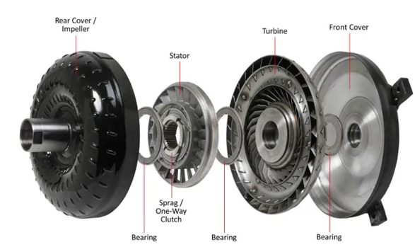
Fig 9. Parts of Torque Convertor
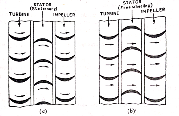
Fig. Flow of fluid in torque converter (a) under low-speed condition the stator deflects the fluid flow back to the impeller, (b) under high-speed condition the stator free wheels and fluid flow is not deflected.
Key Takeaways:
• Torque converter provides constant deviation in the ratio of low to high.
• When this force become very high, the turbine starts rotating in fruitful manner and the automobile starts moving.
- As torque is carried via way of means of the driveshaft, it's far subjected to torsion or shear pressure.
- So they need to be robust sufficient to undergo the pressure at the same time as averting an excessive amount of greater weight as this may growth their inertia.
- Driveshafts are used in a different way in one of a kind cars, with one of a kind configurations for front-wheel pressure, four-wheel pressure, and front-engine rear-wheel pressure in cars.
- The drive shafts also are utilized in cars like motorcycles, locomotives, and marine ships.
Functions of the Propeller
- Shaft In automobiles, the engine is on the front then the front wheels of the automobile are being driven.
- In addition, while the rear wheels meet unevenness with inside the road, the rear axle actions up and down, compressing and increasing with inside the suspension springs.
- Also, the period occupied with the aid of using the propeller shaft changes.
Types of Propeller Shaft
Following are the types of the propeller shaft:
- Single piece type
- Two or three piece type
- Single Piece type
This shaft is utilized in automobiles with a small distance among the engine and axle and in four-wheel-pressure automobiles. Friction welding is implemented with a view to will increase the strength, quality, and sturdiness of the shaft.
2. Two or Three Piece type
Two or 3-piece shafts are used as a part of automobiles with an extended distance among engine and axle, and four-wheel-pressure automobiles. Splitting the propeller shaft into or 3 elements reduces the range of revolutions.
Key Takeaways:
- As torque is carried via way of means of the driveshaft, it's far subjected to torsion or shear pressure.
- The drive shafts also are utilized in cars like motorcycles, locomotives, and marine ships.
- Also, the period occupied with the aid of using the propeller shaft changes.
- . Splitting the propeller shaft into or 3 elements reduces the range of revolutions.
- A slip joint is a mechanical connection among factors that permits for movement however now no longer disconnection among the additives.
- This is executed to maintain the additives from turning into separated, despite the fact that they hold their personal separate functions.
- Even the swing palms in systems as massive as retractable stadium roofs use slip joints.
- Another feature that a slip joint is used for is to permit for a issue connected to every other with the aid of using a slip joint to be adjusted from one role in which it stays constant to a unique constant role.
- Such joints additionally permit for the automatic adjustment being made among pieces.
- These easier styles of slip joints are usually used to make a mechanical tool less difficult to move with the aid of using maintaining the factors of the tool from turning into separated at the same time as permitting them to lower in average size.
- Devices inclusive of tripod legs or objects inclusive of telescopes appoint the usage of those easy slip joints.
• A U-joint (universal coupling) is basically a coupling used to connect two rigid rods having axes inclined with each other, and is applicable in shafts which transmits rotary motion.
• RWD automobiles have U-joints at each end of the drive shaft. U-joints linked to the yoke permits the drive shaft to move backward and forward as automobile passes any obstacles or sink in the road, effectively shortening or lengthening the shaft.
• FWD also use 2 joints i.e., constant velocity (or CV) joints which also compensate for steering changes.
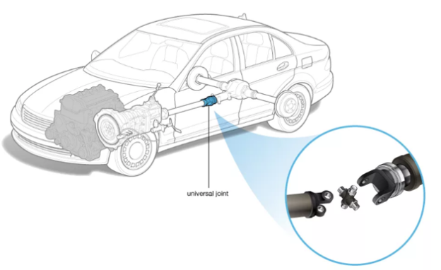
Fig 10. Universal Joint
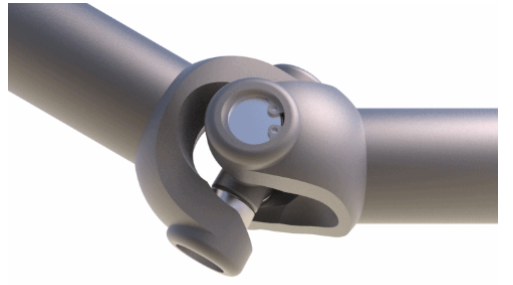
Fig 11 Universal Joint.
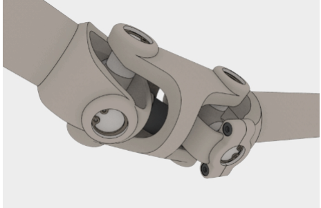
Fig 12 Constant Velocity Universal Joint
The most common type of U- joint is the hook joint (Figure 13) which is highly used as it is very simple and compact in construction and is equitably effective at small angles of propeller shaft movement up and down 18°.
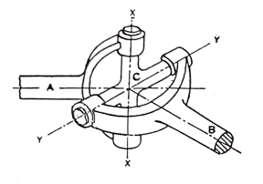
Fig 13 Hooke’s Joint
- The two opposite sides of the cross are supported on the shaft A's yoke, while the other two arms support the cross in the shaft B's yoke.
- The axes of shafts A and B intersect. Each of these shafts has a yoke. Cross four sides.
- Thus, shaft A can have axis XX and shaft B, angular rotation about axis YY. It is thus seen that with the addition of the hook it would be possible to have positive drive allowing angular momentum between shafts A and B.
Key Takeaways (Joints):
- Even the swing palms in systems as massive as retractable stadium roofs use slip joints.
- Such joints additionally permit for the automatic adjustment being made among pieces.
- FWD also use 2 joints i.e., constant velocity (or CV) joints which also compensate for steering changes.
The idea of the differential – that is, to permit wheels set up at the identical axle to rotate independently of every different – is an historic design, with the primary acknowledged example of its use recorded in China at some stage in the first millennium BC.
Although this turned into lengthy earlier than the discovery of the automobile, carts, wagons and chariots nonetheless suffered from the identical trouble of 1 wheel slipping or dragging whilst cornering, growing put on and detrimental roads.
The creation of engines powering the front or rear wheels to propel a car in place of simply dragging them thru horse brought a brand new trouble to triumph over – the way to permit impartial rotation even as nonetheless being capable of electricity each wheels.
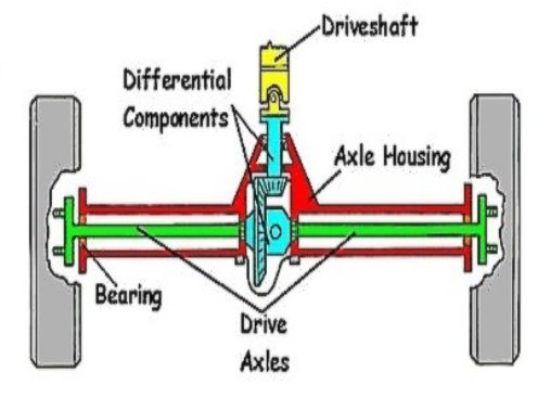
Fig 14: Differential Axle
The earliest cars didn’t hassle trying, they truly powered handiest one wheel on an independent axle. But this turned into some distance from perfect because it supposed they have been underpowered and encountered common troubles with traction on something apart from firm, degree ground.
Eventually this brought about the improvement of the Open Differential earlier than different extra complex sorts have been evolved to triumph over extra complicated using conditions.
Open differential:
A differential in its maximum fundamental shape contains halves of an axle with a equipment on every end, related collectively with the aid of using a 3rd equipment making up 3 facets of a square.
This is generally supplemented with the aid of using a fourth equipment for brought strength, finishing the square.
This fundamental unit is then in addition augmented with the aid of using a hoop equipment being brought to the differential case that holds the fundamental middle gears – and this ring equipment permits the wheels to be powered with the aid of using connecting to the pressure shaft.
Locked differential:
The locked or locking differential is a variation located on a few vehicles, by and large people who burst off road.
It is basically an open differential with the cap potential to be locked in area to create a set axle as opposed to an unbiased one.
The gain of a locked differential is it could benefit a substantially more quantity of traction than an open differential.
Because the torque isn't similarly cut up 50/50 it may channel greater torque to the wheel that has the higher traction - and isn't restricted with the aid of using the decrease traction of the alternative wheel at any given moment.
Because you're not likely to be journeying at pace and are generally journeying over choppy ground, the problem of tyre drag and put on round corners on a set axle is much less of a problem.
Fig 33 shows a simplified view of the live rear axle of a front engine, rear driven automobile. The drive from the propeller shaft comes to the pinion shaft which is supported in bearings in the axle casing.
The crown wheel is in mesh with the pinion and is mounted on shaft on the ends of which are fixed the caps which serve to restrict the wheels in axial direction. The wheels are mounted on bearings on the ends of the axle shaft. In practice, however, there are two half shafts instead of single one shown here.
The weight of the body and load due to occupants is transmitted through springs to the axle casing. The casing itself is supported by road wheels.
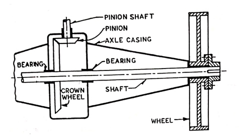
Fig. 15 Rear Axle
Live axle is very big and heavy. It consists of the differential, drive shafts, leaf spring and a tube enfolding all things. Since the whole axle is rigidly fixed to the wheels the Unsprung weight is very high. Without the driving mechanism incorporated, dead axle has much less unsprung weight, so its ride quality is better than a Live Axle.
Unsprung weight is the part of the vehicle that is not riding on top of the suspension, likes the wheels, tyres etc. Unsprung weight is a highly undesirable attribute in suspension design, because with less amount of unsprung load the suspension is able to react faster to humps rather than simply transmitting the shock to the cabin.
The ratio of sprung to unsprung weight is a decisive factor in deciding how smoothly a car ride. A heavier car rides better than a lighter car? It is because the heavier car most likely has a higher sprung to unsprung weight ratio than the lighter car. This also means that lighter cars can be made to ride better than heavier cars if they manage to keep their unsprung weight down. And it also explains why these heavy off roaders still ride so roughly while handling so poorly compared to cars much lighter than them.
Compared to the latest independent suspension, a live axle system has the entire differential assembly, tubing and final driveshaft’s as unsprung masses although the main driveshaft is partly sprung. All current independent suspension has the final driveshafts partially unsprung and main driveshaft(s) and differential assemblies are sprung masses attached to the body. Thus, one can see how much of an unsprung weight penalty there is by using a live axle.
In an RWD car, the rear axle is a live axle and front axle is a dead axle. While in an FWD car it is inverse that is front axle is a live axle and rear axle is the dead axle.
Key Takeaways:
- The earliest cars didn’t hassle trying, they truly powered handiest one wheel on an independent axle.
- It is basically an open differential with the cap potential to be locked in area to create a set axle as opposed to an unbiased one.
- In practice, however, there are two half shafts instead of single one shown here.
- The ratio of sprung to unsprung weight is a decisive factor in deciding how smoothly a car ride.
- In all drives employed for the rear axle, the spring takes the weight of the body. Several drives are used, two of the most important of which are the Hotchkiss drive and the torque-tube drive.
- Hotchkiss drive is the simplest and most widely used type of rear axle drive. In this case, the spring takes the torque response in addition to taking the weight of the body, driving thrust and side thrust.
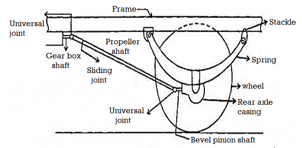
- The propeller shaft is provided with two universal joints and one sliding joint. The spring is rigidly fixed in the middle, to the rear axle.
- The front end of the spring rests firmly on the frame, while the rear end rests in a shackle. Driving thrust is transmitted to the frame by the front half of the springs.
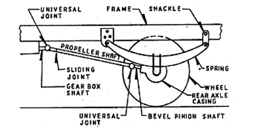
Fig 16. Hotchkiss Drive
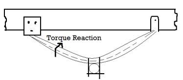
Fig 17. Bending of spring under torque reaction.
- The spring is deflected due to the moment reaction as shown in Fig. 35. Thus, the torque response is taken by the springs.
- Similarly, the springs will deflect in the opposite direction to raise the braking torque. When the springs are deflected in the manner shown, the bevel pinion shaft also changes its position. So, if there is only one universal joint on the front end of the propeller shaft, it will bend in this position.
- To avoid this, another universal joint is used at the rear end of the propeller shaft, when the rear axle moves up and down, it has to rotate in a circle with the front spring support on the frame as the center Is.
- But for propeller shaft motion, the center is in front of the universal joint. This means that during this movement of the rear axle, the length of the propeller shaft must be much greater. This is provided by means of a sliding joint in the propeller shaft.
Key Takeaways:
- Several drives are used, two of the most important of which are the Hotchkiss drive and the torque-tube drive.
- The spring is rigidly fixed in the middle, to the rear axle.
- When the springs are deflected in the manner shown, the bevel pinion shaft also changes its position.
- Driving thrust is transmitted to the frame by the front half of the springs.
- In torque tube drives, the spring supports only the thrust in addition to supporting the weight of the body.
- Torque reactance, braking torque and driving thrust are taken by another member called torque tube.
- One end of the torque is attached to the axle casing, while the other end, which is circular in shape, fits into the cup attached to the frame.
- The torque tube surrounds the propeller shaft. The torque tube takes the torque reaction.
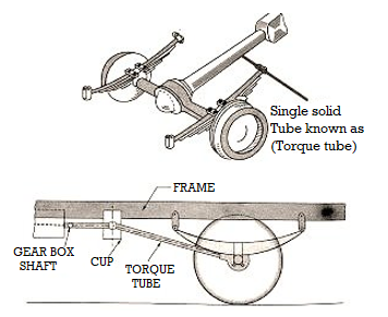
Fig 18. Torque – tube Drive.
- The centerline of the bevel pinion shaft will not shift and will always pass through the center of the spherical cup if the propeller shaft is connected to the gear box shaft via a universal joint located in the center of the spherical cup
- In this case, no universal joint is required at the rear and on the propeller shaft. Also, no sliding joints have been added because in this case both the pinion shaft and the propeller shaft will rotate about the same centre, i.e., about the center of the circular cup. Obviously torque response and driving thrust torque is taken by the tube.
- Important note- In both types of drives the side thrust is taken by leaf spring. If, however, coil springs are used, they are not able to take the side load and, therefore, a separate member is employed in that case. Such a member is usually in the form of a rod of a transverse radius almost parallel to the wheel axis. One end is mounted to the axle casing and the other to the chassis frame. Such rods are commonly called Panhard rods.
Key Takeaways:
- Torque reactance, braking torque and driving thrust are taken by another member called torque tube.
- In this case, no universal joint is required at the rear and on the propeller shaft.
- The torque tube surrounds the propeller shaft. The torque tube takes the torque reaction.
References:
- Automotive Engineering- Hietner.
- Automobile Engineering - Narang.
- Automobile Engineering – Dr. Kirpal Singh
- Automotive Mechanics- Crouse.