Unit - 5
Caster
- Caster angle, is the top to bottom angle of the steering axis and suspension components as they meet the wheel.
- A zero/neutral caster setting would result in a perfectly vertical spring/shock with the center of the wheel positioned directly “south” of the strut mount or upper ball joint (depending upon the vehicle suspension type).
- Caster angle is an alignment adjustment that occurs on the turning wheels only, i.e., the front wheels of a vehicle.
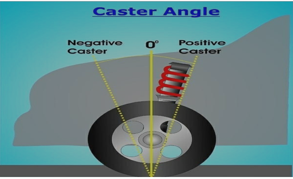
Fig 1. Castor Angle.
- Positive caster positions the lower ball joint in front of the upper ball joint or strut mount. This results in the tire contact patch hitting ground in front of the steering system and suspension components.
- Negative caster positions the lower ball joint behind (rearward of) the upper ball joint or strut mount. Unlike in a positive caster arrangement, the wheel and tire contact patch hit the ground behind the steering system and suspension components.
- Negative caster angle isn’t a setting used by modern road cars. The self-aligning torque and straight-line stability that is characteristic of positive caster, are absent in a negative caster setting. In fact, a “loose” steering wheel and immense front wheel instability would result from a negative caster setup.
Key Takeaways:
- Caster angle is an alignment adjustment that occurs on the turning wheels only, i.e., the front wheels of a vehicle.
- Positive caster positions the lower ball joint in front of the upper ball joint or strut mount.
• Camber is the angle at which the wheel and tire stand relative to the road – assuming it is perfectly flat.
• The easiest way to envision what camber looks like is to view the wheel and tire head on.
• When stationary, the tire maintains a static camber angle, whereas when the car is cornering, due to body roll, the contact patch is reduced. In order to counteract this effect and have the greatest amount of tire on the road while cornering, camber settings must be taken into consideration and adjusted accordingly.
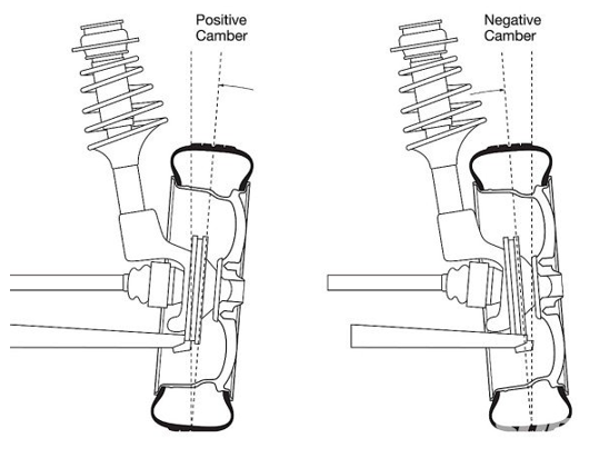
Fig 2. Camber Angle.
Positive camber
Positive camber means that the top of the wheel is pointed outwards rather than the inside. In other words, the wheels are pointing away from the vehicle’s chassis. Before discussing the negative chamber, let us consider how positive camber can affect the car tires.
Effects
One of the most visible impacts of positive camber is that it provides stability. Therefore, it can steer in any direction without much effort. Positive camber can be found mostly on recreational vehicles and agricultural vehicles such as tractors. Moreover, if you are driving on an uneven surface, positive camber will provide the much-desired stability.
Most of the front-wheel-drive vehicles have a non-adjustable camber. However, it does not affect the everyday driver as their only concern is a smooth and comfortable ride. In case of an accident or other damage, the wheel components must be replaced. For optimal performance, the original positive camber must be recreated.
However, it is easier said than done. Recreating an original positive camber for the wheels can be quite tricky and, in some cases, nearly impossible.
Negative camber
Negative camber is when the wheels are inclined towards the chassis of the car. If you are someone who opts for high-speed cornering, then the negative camber is the ideal camber type for you. The angle allows making high speed cornering a breeze. It is made possible as the bottom part of the tires do not come into contact with the surface as much.
The reduced contact with the road surface drastically reduces the pressure on the tires. Hence, it makes high-speed cornering feel like a breeze. Negative camber can be found in F1 racing and other motorsport events. Owners of high-performance cars also prefer to have negative camber.
Effects
As discussed above, negative camber drastically improves the handling of the vehicle. Apart from this, it drastically reduces the vibrations in the wheel. However, there are drawbacks to negative camber as well. One of the drawbacks is that straight-line acceleration will be drastically reduced. The reason is that the angled wheels will need to work harder to reach higher speeds.
Another drawback is that the braking distance will increase, meaning that you will require a greater length of road to bring a vehicle to a stop. You are also more likely to wear out the tires quicker because of the way the wheels are angled. Another drawback is that a negative camber reduces traction on wet surfaces.
Key Takeaways:
• The easiest way to envision what camber looks like is to view the wheel and tire head on.
• Apart from this, it drastically reduces the vibrations in the wheel.
• Positive camber and there effect
• Negative camber and there effect
On modern-day suspension systems, the kingpin is ready at an attitude to the vertical aircraft while considered from the front or rear of the automobile. This attitude is referred to as the king pin inclination. The motive of the KPI is to provide vertical displacement of the automobile in throughout steerage in an upward direction.
- The large the KPI, the bigger the impact.
- This lifting impact produces a self-cantering torque just like that of caster. The KPI additionally generates scrub radius.
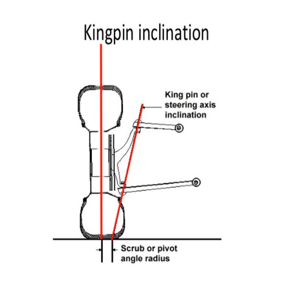
Fig 3: King Pin Inclination
Caster angle, just like KPI, reasons the wheel to upward thrust and fall as well. However, assorted to KPI, the impact is contrary from aspect to aspect. Therefore, with symmetric geometry, the impact of proper steer will roll the auto to the left inflicting a diagonal weight shift. Positive lifting of the auto has a tendency to growth the self-aligning torque while poor lifting of the auto will lessen the self-aligning torque. This offers an surprising sense to the steerage as is the purpose that it's far utilized in concord with KPI.
- Kingpin mindset is a degree of the mindset of the suspension steer axis relative to vertical with inside the front view.
- The steer axis (or kingpin axis) on a traditional double wishbone suspension passes thru the top manage arm and decrease manage arm ball joints.
- On a MacPherson strut, the kingpin axis is described through a line passing thru the strut pinnacle bearing and the decrease ball joint.
Scrub radius is the gap from the steer axis to the centre of the tyre touch patch at floor degree and wheel centre offset is the gap from the kingpin axis to the wheel centre.
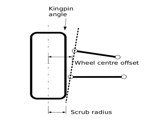
Therefore to persuade far from the directly in advance position, paintings should be performed with the aid of using the driver, this contributes to guidance wheel return ability as this paintings is recovered whilst the guidance wheel is released. Returnability is the tendency of the guidance wheel to self-centre whilst a automobile is riding and is essential for automobile balance. Returnability will increase with expanded kingpin angle. The truth that guidance increases and lowers the automobile additionally manner that expanded kingpin inclination contributes to expanded guidance efforts, even though it isn't always a chief contributor to the general guidance efforts. Kingpin angle (like castor angle) contributes to wheel camber extrude with guidance input. With a wonderful kingpin angle, the out of doors wheel in a nook will benefit wonderful camber and the interior wheel will unfastened wonderful camber.
In popular kingpin angles among 6-14 Dig are visible on manufacturing vehicles. MacPherson strut suspensions might be closer to the higher give up of this variety with values in the direction of the decrease give up completed on double wishbone suspensions. In a brake in bend scenario, this offers an understeer tendency that's suited from a balance factor of view. On the opposite hand, a terrible scrub radius (kingpin axis intersect the floor outboard of the wheel centre line) has balance blessings for cut up mu braking. In the intense scenario, with simplest one wheel braking, the automobile will generally tend to persuade closer to the braking wheel.
The toe-in which ends up from the terrible scrub radius at the braking wheel will counteract this and enhance balance. In maximum manufacturing vehicles, scrub radius is saved to small values (both wonderful and terrible). A scrub radius much less than 10-15 mm might be best however isn't always continually achievable.
Key Takeaways:
- The motive of the KPI is to provide vertical displacement of the automobile in throughout steerage in an upward direction.
- Kingpin mindset is a degree of the mindset of the suspension steer axis relative to vertical with inside the front view.
Wheel toe-in is an angle formed by the centreline of the wheel and the vehicle's longitudinal axis, when viewed from above, the sum of the toe values for each wheel gives the total toe value.
When the extension of the wheel center lines meets in front of the vehicle's direction of travel, it is known as tow-in.
If the lines meet behind the vehicle's direction of travel, it is known as a tow-out.
When the extensions to the wheel center lines are parallel, this is referred to as the zero position, the toe value is rarely given by the manufacturer in degrees, and it is common to give the value expressed in mm which is the point of the circle. Measures the difference in mm between the wheels. Two measurements are taken at the front and rear of the wheel hub, half the distance from the ground to the top of the wheel.
Effect
In a rear-wheel drive vehicle, the rear axle pushes the front axle tyres as they roll along the road. Tyre rolling resistance produces some drag which results in rearward movement of the suspension arms against their bushings.
Due to this, most rear-wheel drive vehicles are provided with some toe-in to compensate for the movement so that the tyres run parallel to each other The case of the front-wheel drive vehicles is just the opposite, wherein the front axle pulls the vehicle through itself (front axle), resulting in forward movement of the suspension arms against their bushings to compensate which negative toe-in, i.e., toe-out is provided.
Toe amount also affects the handling characteristics. Increase in toe-in would result in decreased oversteer and increased directional stability at high speeds, whereas increase in toe-out would result in reduced understeer and greater ease in steering during cornering.
Amount Toe-in initially provided generally does not exceed 3 mm.
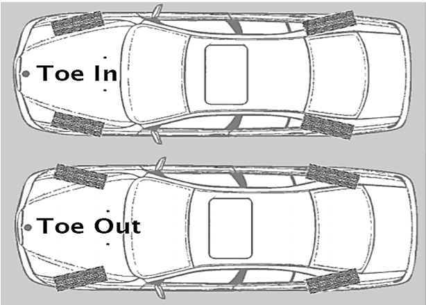
Fig 4. Toe – in And Toe – out
Key Takeaways:
- When the extension of the wheel center lines meets in front of the vehicle's direction of travel, it is known as tow-in.
- Tyre rolling resistance produces some drag which results in rearward movement of the suspension arms against their bushings.
A full-floating axle carries the vehicle's weight on the axle casing, not the half shafts; they serve only to transmit torque from the differential to the wheels. They "float" inside an assembly that carries the vehicle's weight.
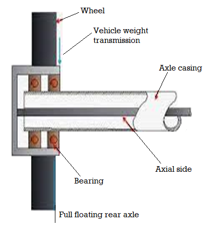
Fig 5. Full Floating Real Axles
Working Principle:
The outer of an axle is made flanged to which the wheel hub is bolted. The axle isn't supported with the aid of using bearing at both quit, and its role is maintained with the aid of using the manner that it's miles supported at each ends. Thus the axle is relieved of all pressure due to the load of the car at the quit thrust.
- A full-floating axle includes the car's weight at the axle casing, now no longer the halfshafts; they serve simplest to transmit torque from the differential to the wheels.
- They "float" interior an meeting that includes the car's weight. Thus the simplest strain it need to undergo is torque (now no longer lateral bending force).
- Full-floating axle shafts are retained via way of means of a flange bolted to the hub, even as the hub and bearings are retained at the spindle via way of means of a big nut.
- In contrast, a semi-floating layout includes the load of the car at the axle shaft itself; there may be a unmarried bearing on the stop of the axle housing that includes the burden from the axle and that the axle rotates through.
To be "semi-floating" the axle shafts need to have the ability to "float" with inside the housing, bearings and seals and now no longer challenge to axial "thrust" and/or bearing preload. Needle bearings and separate lip seals are utilized in semi-floating axles with axle retained with inside the housing at their internal ends commonly with "c-clips" that are 3/4-spherical hardened washers that slide into grooves machined on the internal stop of the shafts and retained in/via way of means of recesses with inside the differential provider facet gears that are themselves retained via way of means of the differential pinion equipment or "spider equipment".
A authentic semi-floating axle meeting locations no facet masses at the axle housing tubes or axle shafts. Axles that are pressed into ball or tapered curler bearings that are in flip retained in/at the axle housings with flanges, bolts and nuts do now no longer "float" and location axial masses at the bearings, housings and simplest a quick phase of the shaft itself that still includes all radial.
Key Takeaways:
- Thus the axle is relieved of all pressure due to the load of the car at the quit thrust.
- Working principle of full floating real axles
The 3 region floating axle has a bearing placed among the hub and the axle casing. Thus the load of the car is transferred to the axle casing, and handiest the aspect thrust and riding torque are taken with the aid of using the axle.
In this bearing is positioned among the axle casing & the hub in place of among the axle casing. At one time, this form of axle become famous for cars & mild business vehicles.
This kind is a compromise among the overall floating kind and the semi floating kind.
- In three-zone floating rear axle, bearings are at the axle casing and hub. In this situation, important a part of car weight is taken with the aid of using axle casing and now no longer with the aid of using axle.
- This is the primary gain of three-zone floating kind over 1/2 of floating kind.
- The axle shafts do now no longer ought to face up to any shearing or bending; it has to take most effective the cease hundreds and riding torque.
- Thus, axle breakdown is much less in this situation as compared to the Semi floating.
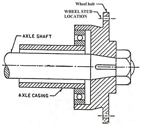
Fig. 6 Three Quarter Axles
Although the 3 zone floating axle is greater dependable however it isn't as easy because the semi-floating axle. The fractional floating axle became moreover used on a few in advance commercial vehicles. The bearing helping the outer end of the axle shaft is emotional from in the shaft housing to the skin. This approach of mounting the axles locations maximum of the weight of the car at the ends of the axle housing rather than the ends of the shaft shafts. The wheel is solidly keyed to a taper at the pinnacle of the axle shaft, as a result side-thrust stays taken through the axle shaft due to the fact the car turns or skids.
Key Takeaways:
- Thus the load of the car is transferred to the axle casing, and handiest the aspect thrust and riding torque are taken with the aid of using the axle.
- This is the primary gain of three-zone floating kind over 1/2 of floating kind.
- The fractional floating axle became moreover used on a few in advance commercial vehicles.
A semi-floating axle may be very not unusual place at the rear of maximum 4WDs. It includes an axle shaft on every facet this is splined at the internal quit in which it associates to the differential and has a wheel flange in which the wheel studs mount at the opposite quit. The wheel hub is hooked up in this spindle and rides on tapered curler bearings.
This layout employs one wheel aid bearing installed at the outer stop of the axle shaft and with inside the axle tube. All the wheel forces along with car weight, wheel facet skid, wheel traction, and torsional drive, are supported through the axle shaft. The outer stop of the axle shaft is supported with inside the axle tube and aid car weight.
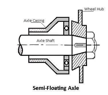
Fig 7: Semi Float Axle
Principle of Working:
By design, a semi floating axle uses a wheel hub that is without delay related to the axle shaft (the hub and axle shaft are normally a single part), it truly is supported with the resource of the usage of a bearing placed near the wheel surrender of the axle. They are the axle of choice in moderate responsibility vehicles, collectively with midsize and 1/2 of of ton pickup.
- The quick rear axle shaft internal cease is supported best be the differential aspect gear.
- The differential case includes the internal bearing among it and the axle shaft housing that helps it.
- The internal cease of the axle shaft is for that reason relieved of the project of helping the burden of the automobile.
- The weight of the automobile is supported through the axle housing.
Now the outer cease of the axle helps the burden of the automobile and takes up cease thrust. Hence, this creation is known as Semi floating rear axle. The internal cease of the axle shaft is splined to the differential aspect gear. The outer cease is flanged and the wheel is bolted at once to it. In a few designs, the hub of the wheel is keyed to the outer cease of the axle shaft. The axle housing helps the wheel bearing, that's positioned in the outer cease of the axle housing. The bearing is hung on the axle through a retainer.
With this association, the brake drum, the wheel, and the bearings retainer plate need to be eliminated which will withdraw the axle shaft. This association effects with inside the axle shaft supporting to guide the burden of the automobile similarly to transmitting rotation to the wheels. Semi-floating stay rear axles are discovered in cars, SUVs, and mid-length vehicles consisting of ½ tonne vehicles and light-obligation pickup vehicles.
Key Takeaways:
- They are the axle of choice in moderate responsibility vehicles, collectively with midsize and 1/2 of of ton pickup.
- The quick rear axle shaft internal cease is supported best be the differential aspect gear.
- The internal cease of the axle shaft is splined to the differential aspect gear.
References:
- Automotive Engineering- Hietner.
- Automobile Engineering - Narang.
- Automobile Engineering – Dr. Kirpal Singh
- Automotive Mechanics- Crouse.