Unit - 2
Actuators and Power Unit
Hydraulic systems are used to control and transmit power. A pump driven by a prime mover such as an electric motor creates a flow of fluid, in which the pressure, direction, and rate of flow are controlled by valves.
“An actuator is used to convert the energy of fluid back into mechanical power.”
The amount of output power developed depends upon the flow rate, the pressure drop across the actuator, and its overall efficiency. Thus, hydraulic actuators are devices used to convert the pressure energy of the fluid into mechanical energy.
Depending on the type of actuation, hydraulic actuators are classified as follows:
- Linear actuator: For linear actuation (hydraulic cylinders).
- Rotary actuator: For rotary actuation (hydraulic motor).
- Semi-rotary actuator: For the limited angle of actuation (semi-rotary actuator).
Hydraulic linear actuators, as their name implies, provide motion in a straight line. The total movement is a finite amount determined by the construction of the unit.
“The function of the hydraulic cylinder is to convert hydraulic power into linear mechanical force or motion.”
Hydraulic cylinders extend and retract a piston rod to provide a push or pull force to drive the external load along a straight-line path. Continuous angular movement is achieved by rotary actuators, more generally known as a hydraulic motor. Semi-rotary actuators are capable of limited angular movements that can be several complete revolutions but 360o or less is more usual.
Hydraulic cylinders are of the following types:
- Single-acting cylinders.
- Double-acting cylinders.
- Telescopic cylinders.
- Tandem cylinders.
2.2.1 Single Acting Cylinder:
- It consists of a piston inside a cylindrical housing called a barrel. On one end of the piston, there is a rod, which can reciprocate. At the opposite end, there is a port for the entrance and exit of oil.
- Single-acting cylinders produce force in one direction by hydraulic pressure acting on the piston. (Single-acting cylinders can exert a force in the extending direction only.)
- The return of the piston is not done hydraulically. In single-acting cylinders, retraction is done either by gravity or by a spring.
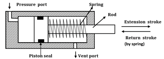
Fig. Single Acting Cylinder
According to the type of return, single-acting cylinders are classified as follows:
- Gravity-return single-acting cylinder.
- Spring-return single-acting cylinder.
Gravity return Single Acting Cylinder:
The figure shows gravity-return-type single-acting cylinders.
- In the push type [Fig(a)], the cylinder extends to lift a weight against the force of gravity by applying oil pressure at the blank end. To retract the cylinder, the pressure is simply removed from the piston by connecting the pressure port to the tank.
- In a pull-type gravity-return-type single-acting cylinder, the cylinder [Fig(b)] lifts the weight by retracting. The blank-end port is the pressure port and the blind-end port is now the vent port. This cylinder automatically extends whenever the pressure port is connected to the tank.

Fig. Gravity Return Single Acting Cylinder (a)push type (b)pull-type
Spring Return Single Acting Cylinder:
A spring-return single-acting cylinder is shown in Fig.
- In push-type [Fig(a)], the pressure is sent through the pressure port situated at the blank end of the cylinder. When the pressure is released, the spring automatically returns the cylinder to the fully retracted position. The vent port is open to the atmosphere so that air can flow freely in and out of the rod end of the cylinder.
- [Fig(b)] shows a pull-type spring-return single-acting cylinder. In this design, the cylinder retracts when the pressure port is connected to the pump flow and extends whenever the pressure port is connected to the tank. Here the pressure port is situated at the rod end of the cylinder.

Fig. Spring Return Single Acting Cylinder (a)Push type (b)Pull type
2.2.2 Double Acting Cylinder
There are two types of double-acting cylinders:
- Double-acting cylinder with a piston rod on one side.
- Double-acting cylinder with a piston rod on both sides.
Double Acting Cylinder with Piston Rod on one side
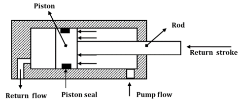
The figure shows the operation of a double-acting cylinder with a piston rod on one side.
- To extend the cylinder, the pump flow is sent to the blank-end port as in Fig. (a). The fluid from the rod-end port returns to the reservoir.
- To retract the cylinder, the pump flow is sent to the rod-end port and the fluid from the blank-end port returns to the tank as in Fig. (b).

(a)
(b)
Fig. Double Acting Cylinder with piston rod on one side
Double Acting Cylinder with piston rod on both sides (Through-rod cylinders)
A double-acting cylinder with a piston rod on both sides (Fig.) is a cylinder with a rod extending from both ends. This cylinder can be used in an application where work can be done by both ends of the cylinder, thereby making the cylinder more productive. Double-rod cylinders can withstand higher side loads because they have an extra bearing, one on each rod, to withstand the loading.
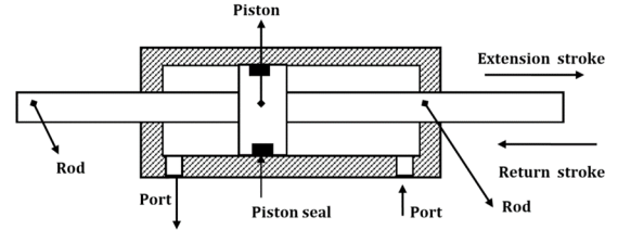
Fig. Double Acting Cylinder with piston rod on both sides
- The main applications of through-rod cylinders are as follows: the same speed is required in both the directions, both ends of the rod can be utilized to do work and the non-working end is used to indicate or signal the position of the load. In some applications, the rod is fixed at both ends and the cylinder body carrying the load moves on the rod.
- A major problem in the manufacture of through-rod cylinders is achieving the correct alignment and concentricity of the cylinder bore, piston, end caps, and rods. Any misalignment can result in excessive seal wear and premature cylinder failure.
2.2.3 Telescopic Cylinder
A telescopic cylinder (shown in Fig.) is used when a long stroke length and a short retracted length are required.
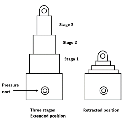
Fig. Telescopic Cylinder
The telescopic cylinder extends in stages, each stage consisting of a sleeve that fits inside the previous stage. One application for this type of cylinder is raising a dump truck bed. Telescopic cylinders are available in both single-acting and double-acting models.
- They generally consist of a nest of tubes and operate on the displacement principle.
- The tubes are supported by bearing rings, the innermost (rear) set of which have grooves or channels to allow fluid flow. The front bearing assembly on each section includes seals and wiper rings.
- Stop rings limit the movement of each section, thus preventing separation.
- When the cylinder extends, all the sections move together until the outer section is prevented from further extension by its stop ring.
- The remaining sections continue out-stroking until the second outermost section reaches the limit of its stroke;this process continues until all sections are extended, the innermost one being the last of all.
2.2.4Tandem Cylinder
- A tandem cylinder, shown in Fig., is used in applications where a large amount of force is required from a small-diameter cylinder.
- The pressure is applied to both pistons, resulting in increased force because of the larger area.
- The drawback is that these cylinders must be longer than a standard cylinder to achieve an equal speed because flow must go to both pistons.
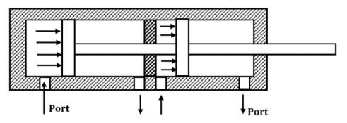
Fig. Tandem Cylinder
The output force (F) and piston velocity (v) of double-acting cylinders are not the same for extension and retraction strokes.

(a)

(b)
During the extension stroke shown in Fig(a), the fluid pressure acts on the entire circular piston area AP. During the retraction stroke, the fluid enters the rod-end side and the fluid pressure acts on the smaller annular area between the rod and cylinder bore (Ap−Ar) as shown by the shaded area in Fig(b) (Ar is the area of the piston rod). Due to the difference in the cross-sectional area, the velocity of the piston changes. Because Ap is greater than (Ap−Ar), the retraction velocity (vret) is greater than the extension velocity (vext) for the same flow rate.
During the extension stroke, the fluid pressure acts on the entire piston area (Ar), while during the retraction stroke, the fluid pressure acts on the annular area (Ap−Ar). This difference in the area accounts for the difference in output forces during extension and retraction strokes. Because Ar is greater than (Ap−Ar), the extension force is greater than the retraction force for the same operating pressure.
Force and velocity during extension stroke:
Velocity

Force

Force and velocity during the retraction stroke
Velocity

Force

Power Developed by hydraulic cylinder
Power = Force x Velocity
In metric units, the kW power developed for either extension or retraction stroke is

Also,
Power during extension stroke is

Power during retraction stroke is

Comparing both equations, we can conclude that the powers during extension and retraction strokes are the same.
Hydraulic motors are rotary actuators. However, the name rotary actuator is reserved for a particular type of unit that is limited in rotation to less than 360o.
“A hydraulic motor is a device which converts fluid power into rotary power or converts fluid pressure into torque.”
Hydraulic motors can be classified as follows:
1. Gear motors.
2. Vane motors.
3. Piston motors:
- Axial piston-type motors.
- Radial piston-type motors.
2.4.1 Gear motors:
- A gear motor develops torque due to hydraulic pressure acting against the area of one tooth. Two teeth are trying to move the rotor in the proper direction, while one net tooth at the center mesh tries to move it in the opposite direction.
- In the design of a gear motor, one of the gears is keyed to an output shaft, while the other is simply an idler gear.
- Pressurized oil is sent to the inlet port of the motor. The pressure is then applied to the gear teeth, causing the gears and output shaft to rotate. The pressure builds until enough torque is generated to rotate the output shaft against the load.
- Most of the gear motors are bidirectional. Reversing the direction of flow can reverse the direction of rotation.
- The gear motors are simple in construction and have good dirt tolerance, but their efficiencies are lower than those of vane or piston pumps and they leak more than the piston units.
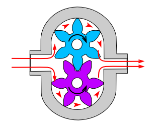
Fig. Hydraulic gear motor
2.4.2 Vane Motor
- An unbalanced Vane motor consists of a circular chamber in which there is an eccentric rotor carrying several spring or pressure-loaded vanes.
- Because the fluid flowing through the inlet port finds more area of vanes exposed in the upper half of the motor, it exerts more force on the upper vanes, and the rotor turns counterclockwise.
- Close tolerances are maintained between the vanes and ring to provide high efficiencies.
- The displacement of a vane hydraulic motor is a function of eccentricity.
- The radial load on the shaft bearing of an unbalanced vane motor is also large because all its inlet pressure is on one side of the rotor.
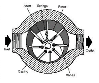
Fig. Unbalanced Hydraulic Vane Motor
The following figure shows the balanced vane motor.
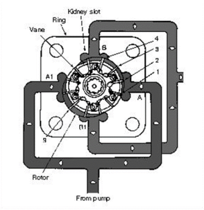
Fig. Balanced Hydraulic Vane Motor
- The radial bearing load problem is eliminated in this design by using a double-lobed ring with diametrically opposite ports.
- Side force on one side of the bearing is canceled by an equal and opposite force from the diametrically opposite pressure port.
- The like ports are generally connected internally so that only one inlet and one outlet port are brought outside.
- The balanced vane-type motor is a reliable open-loop control motor but has more internal leakage than piston-type and therefore generally not used as a servo motor.
2.4.3 Piston Type motor
Piston motors are classified into the following types:
- Axial piston motors.
- Inline Piston Motor
- Bent Axis Piston Motor
2. Radial piston motors.
- Axial Piston Motor
- In axial piston motors, the piston reciprocates parallel to the axis of the cylinder block.
- These motors are available with both fixed-and variable-displacement feature types.
- They generate torque by pressure acting on the ends of pistons reciprocating inside a cylinder block.
- Inline piston motor
The figure illustrates the inline design in which the motor, driveshaft, and cylinder block are centered on the same axis.

Fig. Swash-Plate Inline Piston Motor
- The pressure acting on the ends of the piston generates a force against an angled swashplate.
- This causes the cylinder block to rotate with a torque that is proportional to the area of the pistons.
- The torque is also a function of the swashplate angle.
- The inline piston motor is designed either as a fixed- or a variable-displacement unit.
- The swashplate determines the volumetric displacement.
b. Bent Axis Piston Motor
A bent-axis piston motor is shown in Fig.
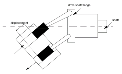
Fig. Bent-axis Piston Motor
- This type of motor develops torque due to pressure acting on the reciprocating piston.
- In this motor, the cylinder block and driveshaft mount at an angle to each other so that the force is exerted on the drive shaft flange.
- Speed and torque depend on the angle between the cylinder block and the drive shaft.
- The larger the angle, the greater the displacement and torque, and the smaller the speed.
- This angle varies from 7.5° (minimum) to 30° (maximum). This type of motor is available in two types, namely fixed-displacement type, and variable-displacement type.
B. Radial piston Motor
- In radial piston-type motors, the piston reciprocates radially or perpendicular to the axis of the output shaft.
- The basic principle of operation of the radial piston motors is shown in Fig.
- Radial piston motors are low-speed high-torque motors that can address a multifarious problem in diverse power transfer applications.

Fig. Radial Piston Motor
These are devices used to convert fluid energy into a torque which turns through an angle limited by the design of the actuator. With the majority of designs, the angle of rotation is limited to 360o although it is possible to considerably exceed this when using piston-operated actuators.
2.5.1 Vane-Type Semi-Rotary Actuator (Single Vane)
A single-vane rotary actuator is shown in Fig.
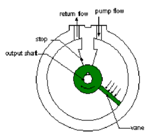
Fig. Vane Type Semi-Rotary Actuator
- A semi-rotary actuator allows only a partial revolution.
- A vane-type semi-rotary actuator consists of a vane connected to an output shaft.
- When hydraulic pressure is applied to one side of the vane, it rotates.
- A stop prevents the vane from rotating continuously.
- The rotation angle in the case of a single-vane semi-rotary actuator is 315°.
2.5.2 Two-Vane-Type Semi-Rotary Actuator
A two-vane rotary actuator is shown in Fig.

Fig. Two Vane Type Semi-Rotary Actuator
- The advantage of this design is that the torque output is increased because the area subjected to pressure is large.
- However, two-vane models cannot rotate as many degrees as can single-vane models.
- It is limited to 100°. Passageways are used to connect the different chambers of the rotary actuator.
The performance of hydraulic motors depends upon many factors such as the precision of their parts, tolerances between the mating parts, etc.Internal leakage between the inlet and outlet affects the volumetric efficiency. Friction between mating parts affects the mechanical efficiency of a hydraulic motor. Gear motors typically have an overall efficiency of 70–75% as compared to vane motors which have 75– 85% and piston motors having 85–95%.
Motor torque is divided into three separate groups:
1. Starting torque: The starting torque is the turning force the motor exerts from a dead stop.
2. Running torque: Running torque is exerted when the motor is running and changes whenever there is a change in fluid pressure.
3. Stalling torque: Stalling torque is the torque necessary to stop the motor.
In most hydraulic motors, the stalling and starting torques are equal. Usually, starting torque is 75–80% of the maximum design torque.
- Volumetric efficiency: The volumetric efficiency of a hydraulic motor is the ratio of theoretical flow rate to the actual flow rate required to achieve a particular speed. The motor uses more flow than the theoretical due to leakage:

2. Mechanical efficiency: The mechanical efficiency of a hydraulic motor is the ratio of actual work done to the theoretical work done per torque revolution. The output torque of a hydraulic motor is less than theoretical due to mechanical friction between the mating parts.

Here, theoretical torque and actual torque are given by


3. Overall efficiency: The overall efficiency of a motor is the ratio of output power to the input power of the motor. Output power is mechanical power output at the shaft and input power is fluid energy supplied to the inlet of the hydraulic motor.


The various kinds of mountings normally used in industries are as follows
- Foot mounting:
It should be designed to give a limited amount of movement on one foot only to allow for thermal or load expansion. That is, the cylinder should be positively located or dowelled at one end only.
2. Rod-end flange or front flange mounting:
During the extended stroke, pressure in the hydraulic fluid acts on the cylinder-end cap, the force set up being transmitted to the front mounting flange through the cylinder body.
3. Rear flange, back flange or head-end flange mounting:
No stress is present in the cylinder owing to load on the extend stroke; only hoop stress is present. The load acts through the fluid onto the rear flange.
4. Trunnion mounting:
It allows angular movement. It is designed to take a shear load only. Bearing should be as close to the cylinder body as possible.
5. Eye or clevis mounting:
There is a tendency for the cylinder to jackknife under load. Sideloading of the bearing must be carefully considered.
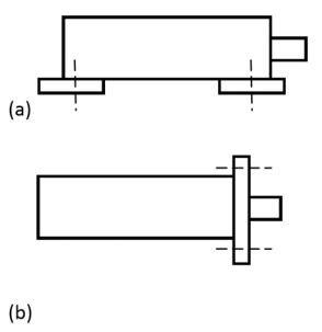

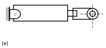
Fig. (a) Foot mounting; (b) rod-end flange or front flange mounting; (c) rear flange, back flange or head-end flange mounting; (d) trunnion mounting; (e) eye or clevis mounting.
- For the prevention of shock due to stopping loads at the end of the piston stroke, cushion devices are used.
- Cushions may be applied at either end or both ends.
- They operate on the principle that as the cylinder piston approaches the end of the stroke, an exhaust fluid is forced to go through an adjustable needle valve that is set to control the escaping fluid at a given rate.
- This allows the deceleration characteristics to be adjusted for different loads.
- When the cylinder piston is actuated, the fluid enters the cylinder port and flows through the little check valve so that the entire piston area can be utilized to produce force and motion.
A typical cushioning arrangement is shown in Fig.
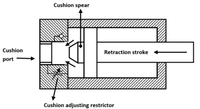
Fig. Hydraulic Cylinder with cushioning
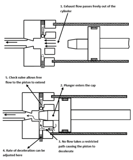
Fig. Operations of Cylinder Cushions
The hydraulic power unit is also termed as a hydraulic power pack.
The unit comprises of all those elements which are necessary to generate a pressurized fluid.
Mechanical energy is converted into hydraulic energy by using a pump that is driven by an electric motor.
Any power unit consists of the following components:
- Electric motor
- Hydraulic pump
- Oil Tank
- Valve Manifold
- Relief valve
- DCV
- Return Filter
- Filling plug with air breather
- Pressure gauge
- Pressure gauge shutoff valve
Types of power unit:
- Stationary Power unit:
These power units are fixed at one location where no movement of the power unit is done. They are placed on a solid foundation and bolted to it so that it produces minimum vibration.
2. Portable Power unit:
These power units are called portable because they can be moved from one location to another. They are compact in size and easy to handle.
A reservoir is constructed with steel plates. The inside surface is painted with a sealer to prevent rust due to condensed moisture. At the bottom, it contains a drain plug to allow the complete drainage of the tank when required.
A removable head can be provided for easy access during cleaning. A vented breather cap is also included that contains an air filtering screen. This allows the tank to breathe as the oil level changes due to system demand requirements.
The functions of a fluid reservoir in a power hydraulic system are as follows:
- To provide a chamber in which any change in the volume of fluid in a hydraulic circuit can be accommodated. When the cylinder extends, there is an increased volume of fluid in the circuit and consequently, there is a decrease in the reservoir level.
- To provide a filling point for the system.
- To serve as a storage space for the hydraulic fluid used in the system.
- It is used as the location where the fluid is conditioned.
- To provide a volume of fluid that is relatively stationary to allow entrained air to separate and heavy contaminants to settle. The reservoir is where sludge, water, and metal slips settle.
- It is a place where the entrained air picked up by the oil is allowed to escape.
- To accomplish the dissipation of heat by its proper design and to provide a radiating and convective surface to allow the fluid to cool.
2.10.1Construction
Schematic diagram of the hydraulic reservoir is shown in Fig
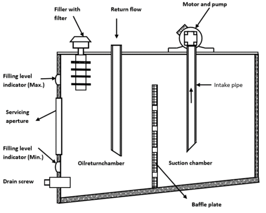
Fig. Hydraulic Reservoir
There are many components mounted on the reservoir and each one of them having specific features.
Following are the features of a hydraulic reservoir:
- Filler cap (breather cap):
It should be airtight when closed but may contain the air vent that filters air entering the reservoir to provide a gravity push for proper oil flow.
- Oil level gauge:
It shows the level of oil in the reservoir without having to open the reservoir.
- Baffle plate:
It is located lengthwise through the center of the tank and is two-third the height of the oil level. It is used to separate the outlet to the pump from the return line. This ensures a circuitous flow instead of the same fluid being recirculated. The baffle prevents local turbulence in the tank and allows foreign material to settle, get rid of entrapped air, and increase heat dissipation.
- Suction and return lines:
They are designed to enter the reservoir at points where air turbulence is the least. They can enter the reservoir at the top of the sides, but their ends should be near the bottom of the tank. If the return line is above the oil level, then returning oil can foam and draw in air.
- Intake filter:
It is usually a screen that is attached to the suction pipe to filter hydraulic oil.
- Drain plug:
It allows all oil to be drained from the reservoir. Some drain plugs are magnetic to help remove metal chips from the oil.
- Strainers and filters:
Strainers and filters are designed to remove foreign particles from the hydraulic fluid.
2.10.2 Types of Reservoirs:
Industrial reservoirs come in a variety of styles. Some of them are the following:
- Non-pressurized:
The reservoir may be vented to the atmosphere using an air filter or a separating diaphragm. The type most commonly used in industry, normally, has an air breather filter, although, in very dirty environments, diaphragms or airbags are used.
2. Pressurized:
A pressurized reservoir usually operates between 0.35 and 1.4 bar and has to be provided with some method of pressure control; this may be a small air compressor maintaining a set charge pressure. In motor circuits where there is a little change in fluid volume in the reservoir, a simple relief valve may be used to limit the air pressure that alters with changes in temperature. The advantages of a pressurized reservoir are that it provides boost pressure to the main pump and prevents the ingress of atmospheric dirt.
2.11.1Seals
“Seals are used in hydraulic systems to prevent excessive internal and external leakage and to keep out contamination.”
Various functions of seals include the following:
- They prevent leakage – both internal and external.
- They prevent dust and other particles from entering into the system.
- They maintain pressure.
- They enhance the service life and reliability of the hydraulic system.
Classification of hydraulic seals
1. According to the method of sealing:
- Positive sealing: A positive seal prevents even a minute amount of oil from getting past. A positive seal does not allow any leakage whatsoever (external or internal).
- Non-positive sealing:A non-positive seal allows a small number of internal leakages, such as the clearance of the piston to provide a lubrication film.
2. According to the relative motion existing between the seals and other parts:
- Static seals: These are used between mating parts that do not move relative toone another. Typical examples are flange gaskets and seals, o-rings, etc. These are relatively simple. They are essentially non-wearing and usually trouble-free if assembled properly.
- Dynamic seals: These are assembled between mating parts that move relative to each other. Hence, dynamic seals are subject to wear because one of the mating parts rubs against the seal.
3. According to geometrical cross-section:
- O-ring seal: O-ring is the most widely used seal for hydraulic systems. It is a molded synthetic rubber seal that has a round cross-section in its free state. O-ring can be used for the most static and dynamic conditions. It gives effective sealing through a wide range of pressures, temperatures, and movements
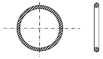
Fig. O-ring
- V-ring seal and U-ring seal: V- and U-ring seals are compression-type seals used in virtually all types of reciprocating motion applications. These include piston rods and piston seals in pneumatic and hydraulic cylinder, press rank, jacks, and seals on plungers and piston in reciprocating pumps. They are also readily suited to certain slow rotary applications such as valve stems. These packings (which can be molded into U-shapes as well as V-shapes) are frequently installed in multiple quantities for more effective sealing.

Fig. V-ring and U-ring Seal
- T-ring seal: T-ring seal isa dynamic seal that is extensively used to seal cylinder-pistons, piston rods, and other reciprocating parts. It is made of synthetic rubber molded in the shape of the cross-section T and reinforced by backup rings on either side. The sealing edge is rounded and seals very much like an O-ring.
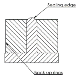
Fig. T-ring seal
- Piston rings: Piston rings are seals that are universally used for cylinder pistons. Metallic piston rings are made of cast iron or steel and are usually plated or given an outer coating of materials such as zinc phosphate or manganese phosphate to prevent rusting and corrosion. Piston rings offer substantially less opposition to motion than synthetic rubber (elastomer) seals.
4. According to the type of seal material used
- Leather: This material is rugged and inexpensive. However, it tends to squeeze when dry and cannot operate above 90oC which is inadequate for many hydraulic systems. Leather does not operate well at cold temperatures to about −50oC.
- Buna-N: This material is rugged and inexpensive and wears well. It has a rather wide operating temperature range (−45–110oC) during which it maintains its good sealing characteristics.
- Silicone: This elastomer has an extremely wide temperature range (−65–232oC). Hence, it is widely used for rotating shaft seals and static seals where a wide operating temperature is expected. Silicone is not used for reciprocating seal applications because it has a low tear resistance.
- Neoprene: This material has a temperature range of 50–120oC. It is unsuitable above 120oC because it tends to vulcanize.
- Tetrafluoroethylene: This material is the most widely used plastic for seals of hydraulic systems. It is a tough, chemically inert, waxy solid, which can be processed only by compacting and sintering. It has excellent resistance to chemical breakdown up to temperatures of 370oC. It also has an extremely low coefficient of friction. One major drawback is its tendency to flow under pressure, forming thin, feathery films. This tendency to flow can be greatly reduced by the use of filler materials such as graphite, metal wires, glass fibers, and asbestos.
- Viton: This material contains about 65% fluorine. It has become almost a standard material for elastomer-type seals for use at elevated temperatures up to 240oC. Its minimum operating temperature is 28oC.
2.11.2 Filters and Strainers
- Filters:
They are devices whose primary function is the retention, by some fine porous medium, of insoluble contaminants from the fluid. Filters are used to pick up smaller contaminant particles because they can accumulate them better than a strainer. Generally, a filter consists of fabricated steel housing with an inlet and an outlet. The filter elements are held in position by springs or other retaining devices. Because the filter element is not capable of being cleaned, that is, when the filter becomes dirty, it is discarded and replaced by a new one. Particle sizes removed by filters are measured in microns. The smallest sized particle that can be removed is as small as 1 µm. A strainer is a device whose function is to remove large particles from a fluid using a wire screen. The smallest sized particle that can be removed by a strainer is as small as 0.15 mm or 150 µm.
2. Hydraulic strainers:
A strainer is a coarse filter. Fluid flows more or less straight through it. A strainer is constructed of a fine wire mesh screen or screening consisting of a specially processed wire of varying thickness wrapped around metal frames. It does not provide as fine a screening action as filters do, but offers less resistance to flow and is used in pump suction lines where pressure drop must be kept to a minimum. A strainer should be as large as possible or wherever this is not practical, two or more may be used in parallel.
“A hydraulic accumulator is a device that stores the potential energy of an incompressible fluid held under pressure by an external source against some dynamic force.”
This dynamic force can come from different sources. The stored potential energy in the accumulator is a quick secondary source of fluid power capable of doing useful work.
There are three basic types of accumulators:
2.12.1 Weight-loaded or gravity accumulator:
The schematic diagram of the weight loaded accumulator is shown in Fig.
- It is a vertically mounted cylinder with a large weight.
- When the hydraulic fluid is pumped into it, the weight is raised.
- The weight applies a force on the piston that generates pressure on the fluid side of the piston.
- The advantage of this type of accumulator over other types is that it applies constant pressure on the fluid throughout its range of motion.
- The main disadvantage is its extremely large size and heavyweight. This makes it unsuitable for mobile applications.
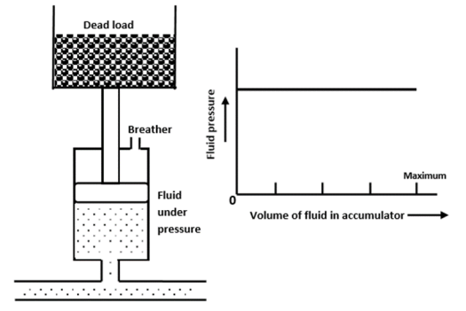
Fig. Dead Weight Accumulator
2.12.2 Spring-loaded Accumulator
- A spring-loaded accumulator stores energy in the form of a compressed spring.
- This type of accumulator delivers only a small volume of oil at relatively low pressure.
- Furthermore, the pressure exerted on the oil is not constant as in the dead-weight-type accumulator.
- As the springs are compressed, the accumulator pressure reaches its peak, and as the springs approach their free lengths, the accumulator pressure drops to a minimum.
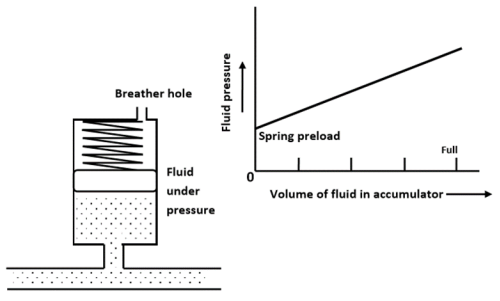
Fig. Spring-loaded Accumulator
2.12.3 Gas loaded Accumulator
A gas-loaded accumulator is popularly used in industries. Here the force is applied to the oil using compressed air.
There are two types of gas-loaded accumulators:
Non-separator-type accumulator:
Here the oil and gas are not separated. Hence, they are always placed vertically.

Fig. Non-separator Type Accumulator
Separator-type accumulator:
Here the oil and gas are separated by an element.
Based on the type of element used to separate the oil and gas, they are classified as follows:
- Piston-type accumulator:
It consists of a cylinder with a freely floating piston with proper seals. Its operation begins by charging the gas chamber with a gas (nitrogen) under a pre-determined pressure. This causes the free sliding piston to move down. Once the accumulator is pre-charged, hydraulic fluid can be pumped into the hydraulic fluid port. As the fluid enters the accumulator, it causes the piston to slide up, thereby compressing the gas that increases its pressure and this pressure is then applied to the hydraulic fluid through the piston.
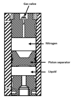
Fig. Piston Type Accumulator
II. Diaphragm accumulator
In this type, the hydraulic fluid and nitrogen gas are separated by a synthetic rubber diaphragm.
The advantage of a diaphragm accumulator over a piston accumulator is that it has no sliding surface that requires lubrication and can, therefore, be used with fluids having poor lubricating qualities. It is less sensitive to contamination due to the lack of any close-fitting components.
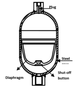
Fig. Diaphragm-type Accumulator
III. Bladder accumulator
It functions in the same way as the other two accumulators.
Here the gas and the hydraulic fluid are separated by a synthetic rubber bladder. The bladder is filled with nitrogen until the designed pre-charge pressure is achieved. The hydraulic fluid is then pumped into the accumulator, thereby compressing the gas and increasing the pressure in the accumulator. The port cover is a small piece of metal that protects the bladder from damage as it expands and contacts the fluid port.
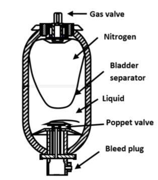
Fig. Bladder-type Accumulator
2.12.4 Sizing of Accumulator for isothermal conditions
For isothermal condition, the Boyle–Mariotte law can be rewritten in terms of V1 and V2 as


The difference between V1 at the minimum operating pressure P1 and V2 at the maximum operating pressure P2 gives the amount of the stored fluid . Thus,


In the above equations, V1 and V2 are nitrogen volumes at the pressures P1 and P2, and V0 is the nitrogen pre-charge volume at the pressure P0 in liters. It is the maximum volume of gas that can be stored in the accumulator.
2.12.5 Sizing of Accumulators for Adiabatic Condition
Starting from the basic formula,

It can be shown that for adiabatic conditions, the values of maximum nitrogen volume V0 at the pre-charge pressure P0 and the stored volume of oil are given by the following equations:

“A hydraulic intensifier is a hydraulic machine for transforming hydraulic power at low pressure into a reduced volume at higherpressure.”
A hydraulic intensifier is a device that is used to increase the intensity of pressure of any hydraulic fluid or water, with the help of the hydraulic energy available from a huge quantity of water or hydraulic fluid at low pressure.
These devices are very important in the case of hydraulic machines, mainly hydraulic presses, which require water or hydraulic fluid at very high pressure which cannot be obtained from the main supply directly.
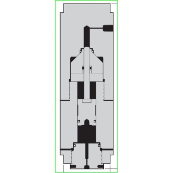
Fig. Hydraulic Intensifier

Fig. Application of Hydraulic Intensifier
In a hydraulic system, due to pumping action heat is generated. The temperature affects oil viscosity. Such changes are viscosity are not desirable in hydraulics. Thus temperature switches are used to measure the amount of heat energy that is generated by a system and take appropriate action when the temperature goes beyond or below the set value.
There are four commonly used temperature sensor types:
1. Negative Temperature Coefficient (NTC) thermistor
A thermistor is a thermally sensitive resistor that exhibits a large, predictable, and precise change in resistance correlated to variations in temperature. An NTC thermistor provides a very high resistance at low temperatures. As temperature increases, the resistance drops quickly. Because an NTC thermistor experiences such a large change in resistance per °C, small changes in temperature are reflected very fast and with high accuracy (0.05 to 1.5 °C). Because of its exponential nature, the output of an NTC thermistor requires linearization. The effective operating range is -50 to 250 °C for glass encapsulated thermistors or 150°C for standard.
2. Resistance Temperature Detector (RTD)
An RTD, also known as a resistance thermometer, measures temperature by correlating the resistance of the RTD element with temperature. An RTD consists of a film or, for greater accuracy, a wire wrapped around a ceramic or glass core. The most accurate RTDs are made using platinum but lower-cost RTDs can be made from nickel or copper. However, Nickle and copper are not as stable or repeatable. Platinum RTDs offer a highly accurate and fairly linear output (0.1 to 1 °C) across -200 to 600 °C. While providing the greatest accuracy, RTDs also tend to be the most expensive of temperature sensors.
3. Thermocouple
This temperature sensor type consists of two wires of different metals connected at two points. The varying voltage between these two points reflects proportional changes in temperature. Thermocouples are nonlinear, requiring conversion when used for temperature control and compensation, typically accomplished using a lookup table. Accuracy is low, from 0.5 °C to 5 °C. However, they operate across the widest temperature range, from -200 °C to 1750 °C.
4. Semiconductor-based sensors
A semiconductor-based temperature sensor is placed on integrated circuits (ICs). These sensors are effectively two identical diodes with temperature-sensitive voltage vs current characteristics that can be used to monitor changes in temperature. They offer a linear response but have the lowest accuracy of the basic sensor types at 1 °C to 5 °C. They also have the slowest responsiveness (5 s to 60 s) across the narrowest temperature range (-70 °C to 150 °C).
- If the pump is discharging oil at high pressure then the outlet pipe may get burst.
- If the pump is not discharging the oil at the desired pressure, the possible cause is low suction pressure.
- Also if the pressure inside the pump falls below the vapor pressure of the oil, it may lead to cavitation.
- In all cases, a device is required which reacts to the dynamic working conditions of the pump; this device is called a pressure switch.
- The pressure switch is a device that maintains the oil pressure of the pump at a designed or set value.
- The main action of the pressure switch is to stop the pump in case the pressure rises or falls beyond the set range.
- In a hydraulic system, the availability of working fluid in good quality and quantity is mandatory for efficient and effective operation.
- The level sensors are the device that takes care of the quantity part.
- In other words, the level sensor detects the amount of working fluid in the system.
- If the level goes below the desired or set value, it sends a signal for appropriate action.
- For example, in a hydraulic braking system, a certain amount of brake oil is required for effective braking. If the oil level is not maintained, it may to leakage in the system.
- Thus, level sensors act as protective as well as indicator devices.
References:
1. Pipenger J.J, Industrial Hydraulics, McGraw Hill
2. Pinches, Industrial Fluid Power, Prentice Hall
3. Yeaple, Fluid Power Design Handbook
4. Andrew A. Parr, Hydraulics and Pneumatics, Elsevier Science and Technology Books
5. ISO - 1219, Fluid Systems and components, Graphic Symbols
6. Standard Manufacturer’s Catalogues