Unit - 3
Fluid Power Control
“Direction Control Valves are the valves which determine the path through which a fluid transverses a given circuit.”
The function of a DCV is to control the direction of fluid flow in any hydraulic system.
A DCV does this by changing the position of internal movable parts.
DCV is mainly required for the following purposes:
- To start, stop, accelerate, decelerate, and change the direction of motion of a hydraulic actuator.
- To permit the free flow from the pump to the reservoir at low pressure when the pump’s delivery is not needed into the system.
- To vent the relief valve by either electrical or mechanical control.
- To isolate a certain branch of a circuit.
3.1.1 Classification of DCV
Classification of DCV’s based Fluid Path
- Check valves.
- Shuttle valves.
- Two-way valves.
- Three-way valves.
- Four-way valves.
Classification of DCVs based on Design Characteristics
- An internal valve mechanism that directs the flow of fluid. Such a mechanism can either be a poppet, a ball, a sliding spool, a rotary plug, or a rotary disk.
- Several switching positions (usually 2 or 3).
- Several connecting ports or ways.
- Method of valve actuation that causes the valve mechanism to move into an alternate position.
Classification of DCVs based on the Control Method
- Direct controlled DCV:
A valve is actuated directly on the valve spool. This is suitable for small-sized valves.
- Indirect controlled DCV:
A valve is actuated by a pilot line or using a solenoid or by the combination of electrohydraulic and electro-pneumatic means. The use of solenoid reduces the size of the valve. This is suitable for large-sized valves.
Classification of DCVs based on the Construction of Internal Moving Parts
- Rotary spool type:
In this type, the spool is rotated to change the direction of the fluid. It has longitudinal grooves. The rotary spools are usually manually operated.
- Sliding spool type:
This consists of a specially shaped spool and a means of positioning the spool. The spool is fitted with precision into the body bore through the longitudinal axis of the valve body. The lands of the spool divide this bore into a series of separate chambers. The ports of the valve body lead into these chambers and the position of the spool determines the nature of interconnection between the ports.
3.1.2 Actuation of DCV
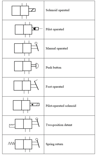
Direction control valves may be actuated by a variety of methods. Actuation is the method of moving the valve element from one position to another.
There are four basic methods of actuation:
- Manually operated: In manually operated DCVs, the spool is shifted manually by moving a handle pushing a button or stepping on a foot pedal. When the handle is not operated, the spool returns to its original position by means of a spring.
- Mechanically operated: The spool is shifted by mechanical linkages such as cam and rollers.
- Solenoid operated: When an electric coil or a solenoid is energized, it creates a magnetic force that pulls the armature into the coil. This causes the armature to push the spool of the valve.
- Pilot operated: A DCV can also be shifted by applying a pilot signal (either hydraulic or pneumatic) against a piston at either end of the valve spool. When pilot pressure is introduced, it pushes the piston to shift the spool.
Several combinations of actuation are possible using these four basic methods. Graphical symbols of such combinations are given in Table
The simplest DCV is a check valve.
A check valve allows flow in one direction but blocks the flow in the opposite direction.
It is a two-way valve because it contains two ports.
The figure below shows the graphical symbol of a check valve along with its no-flow and free-flow directions.

Fig. Graphical Symbol of Check Valve
There are two main types of check valve:
- Ball Type
- Poppet Type
3.2.1Ball Type Check Valve
- In Fig. Below, a light spring holds the ball against the valve seat.
- Flow coming into the inlet pushes the ball off the seat against the light force of the spring and continues to the outlet.
- Very low pressure is required to hold the valve open in this direction.
- If the flow tries to enter from the opposite direction, the pressure pushes the ball against the seat and the flow cannot pass through.
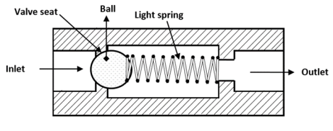
Fig. Ball-type Check Valve
3.2.2Poppet Type Check Valve
- The figure below provides two schematic drawings showing the operation of a poppet check valve.
- A poppet is a specially shaped plug element held on a valve seat by a light spring.
- Fluid flows through the valve in the space between the seat and poppet.
- In the free flow direction, the fluid pressure overcomes the spring force.
- If the flow is attempted in the opposite direction, the fluid pressure pushes the poppet in the closed position. Therefore, no flow is permitted.
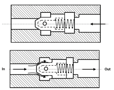
Fig. Poppet type check valve: open and closed position
3.2.3Pilot operated Check Valve
- This type of check valve always permits free flow in one direction but permits flow in the normally blocked opposite direction only if the pilot pressure is applied at the pilot pressure point of the valve.
- The check valve poppet has the pilot piston attached to the threaded poppet stem by a nut.
- The light spring holds the poppet seated in a no-flow condition by pushing against the pilot piston.
- The purpose of the separate drain port is to prevent oil from creating a pressure build-up at the bottom of the piston.
- The dashed line in the graphical symbol represents the pilot pressure line connected to the pilot pressure port of the valve.
- Pilot check valves are used for locking hydraulic cylinders in position.
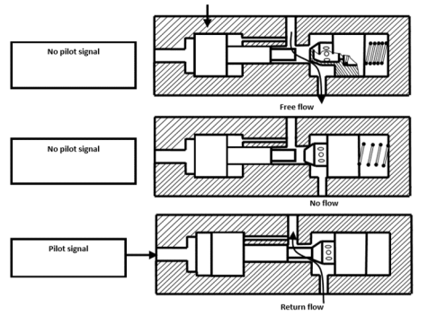
Fig. Pilot operated check valve
A shuttle valve allows two alternate flow sources to be connected in a one-branch circuit.
The valve has two inlets P1 and P2 and one outlet A. Outlet A receives flow from an inlet that is at a higher pressure.
The figure shows the operation of a shuttle valve.
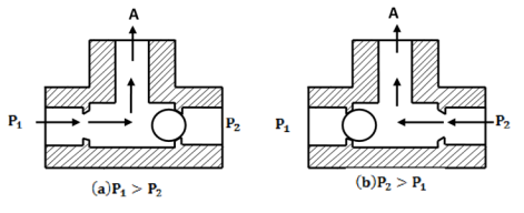
Fig. Shuttle Valve
If the pressure at P1 is greater than that at P2, the ball slides to the right and allows P1 to send flow to outlet A. Fig (a)
If the pressure at P2 is greater than that at P1, the ball slides to the left and P2 supplies flow to outlet A. Fig (b)
A shuttle valve is called an “OR” valve because receiving a pressure input signal from either P1 or P2 causes a pressure output signal to be sent to A.
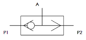
Fig. Symbol of Shuttle Valve
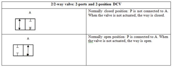
3.4.12/2 DCV (Normally Closed):
- This particular valve has two ports labeled P and A.
- P is connected to the pump line and A is connected to the outlet to the system.
- Figure (a) shows the valve in its normal state and its corresponding symbol. The valve is held in this position by the force of the spring. In this position, the flow from the inlet port P is blocked from going to the outlet port A.
- Figure (b) shows the valve in its actuated state and its corresponding symbol. The valve is shifted into this position by applying a force to overcome the resistance of the spring. In this position, the flow is allowed to go to the outlet port.
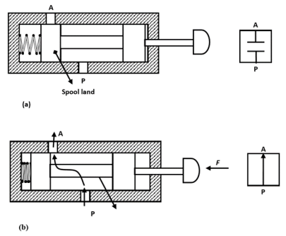
Fig. 2/2 DCV (normally closed)
3.4.22/2 DCV (Normally Open)
- The spring holds the valve in a position in which ports P and Aare connected as shown in Fig (a).
- When the valve is actuated, the flow is blocked from going to A as shown in Fig (b).

Fig. 2/2 DCV (normally open)
3.4.3Application of 2/2 DCV
- A pair of two-way valves are used to fill and drain a vessel.
- In Fig (a), valve 1 is shifted to the open position, while valve 2 remains closed. This fills the vessel.
- In Fig (b), valve 2 is shifted to open position and valve 1 remains closed. This drains the vessel.
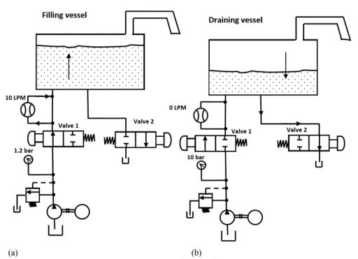
Fig. Application of 2/2 DCV
Three-way valves either block or allow flow from an inlet to an outlet. They also allow the outlet to flow back to the tank when the pump is blocked, while a two-way valve does not.
A three-way valve has three ports, namely, a pressure inlet (P), an outlet to the system (A), and a return to the tank (T).
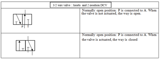
3.5.13/2 DCV (Normally Closed)
- In its normal position, the valve is held in position by a spring as shown in Fig (a). In the normal position, the pressure port P is blocked and outlet A is connected to the tank.
- In the actuated position shown in Fig (b), the pressure port is connected to the tank and the tank port is blocked.
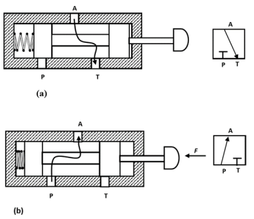
Fig. 3/2 DCV (normally closed)
3.5.23/2 DCV (Normally Open)
- The figure shows a three-way two-position DCV (normally open) with push-button actuation and spring return.
- In the normal position, shown in Fig (a), the valve sends pressure to the outlet and blocks the tank port in the normal position.
- In the actuated position, shown in Fig (b) the pressure port is blocked and the outlet is vented to the tank.

Fig. 3/2 DCV (normally open)
3.5.3Application of 3/2 DCV (Control of Double Acting Cylinder)
Double-acting cylinders can be controlled with two 3/2-way valves so arranged that when one valve pressurizes one end of the cylinder, the other valve exhausts the other end and vice versa
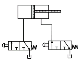
Fig. Control of Double Acting Cylinder by two 3/2 DCV’s
- Four-way DCVs are capable of controlling double-acting cylinders and bidirectional motors.
- The figure shows the operation of a typical 4/2 DCV.
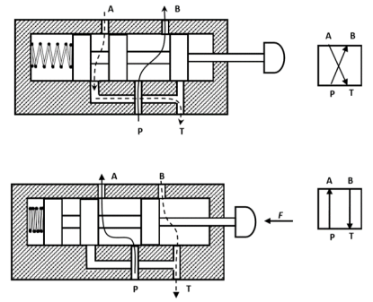
Fig. 4/2 DCV
- A four-way has four ports labeled P, T, A, and B.
- P is the pressure inlet and T is the return to the tank; A and B are outlets to the system.
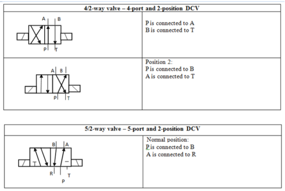
- In the normal position, pump flow is sent to outlet B. Outlet A is connected to the tank.
- In the actuated position, the pump flow is sent to port A and port B connected to tank T.
- In four-way DCVs, two flows of the fluids are controlled at the same time, while two-way and three-way DCVs control only one flow at a time.
3.6.1Application of 4/2-way valve to control a double-acting cylinder
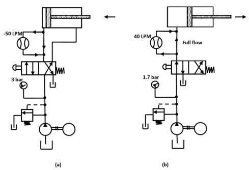
Fig. Control of Double Acting Cylinder by 4/2 DCV
- When the valve is in the normal position, the pump line is connected to the end of the cylinder and the blind end is connected to the tank as shown in Fig (a).
- The cylinder retracts when the cylinder is in this position.
- When the cylinder is fully retracted, the pump flow goes over to the pressure relief valve and back to the tank.
- In Fig (b), the pump line is connected to the blind end of the cylinder and the rod end is connected to the tank. This causes the cylinder to extend.
- When the cylinder is fully extended, the pump flow again goes over the pressure relief valve to the tank.
3.6.2Application of 4/2 DCV for controlling bi-directional motors
- A four-way DCV is also used to control bi-directional hydraulic motors. The figure shows the schematic for this application.
- Unlike the cylinder, the motor rotates continuously and does not force the fluid over the pressure relief valve.
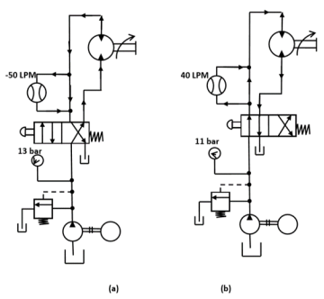
Fig. Control of Bidirectional motor with 4/2 DCV
3.6.3Neutral (Central) positions
- The four-way, two-position DCVs used in the previous two applications are sometimes impractical because they continually send pump flow and pressure to the actuator in one direction or the other.
- Many cylinders and motor applications require a third DCV position or neutral in which the actuator is subjected to pump pressure.
- Four-way three-position circuits are therefore used in many hydraulic circuits.
Many types of neutrals are available; the most common of them are as follows:
- Closed neutral.
- Tandem neutral.
- Float neutral.
- Open neutral.
- Regenerative neutral.
Application of 4/3 DCV (closed neutral) for controlling a double-acting cylinder
- The valve shown here is spring-centered, which means that it always returns to the neutral position automatically when not actuated.
- For closed neutral, the pump line is blocked so that the flow must pass over the pressure relief valve the pressure is at the system maximum.
- This is a wasteful thing because it generates power in the form of pressure and flow, but does not use it. The wasted energy in the system goes as heat. This is undesirable because the hydraulic fluid becomes thinner (less viscous) as it heats up.
- When the fluid becomes too thin, it does not lubricate effectively. This is the result of increased wear.
- The outlet lines to the cylinder are blocked, so the cylinder is held trimly in position. This is because the lines are full of incompressible hydraulic fluid.
- This type of neutral could also be used to control a motor. Just like the cylinder, the motor is held tired in position when the valve is in the neutral.
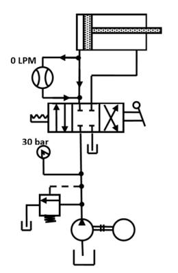
Fig. Application of closed neutral position in 4/3 DCV
Application of 4/3 DCV (tandem neutral) for controlling a double-acting cylinder
- The pump flow is allowed to flow back to the tank through the DCV when it is in the neutral.
- This is a very desirable situation because only pressure in the pump line is due to the flow resistance of the lines and DCV.
- This keeps the pressure low when the valve is in the neutral. In this situation, the system is said to be unloaded because the power consumption is reduced.
- This wastes much less energy than does a closed central neutral that forces the fluid over the pressure relief valve at high pressure.
- The cylinder is held in position with a tandem neutral because the outlet port is blocked.
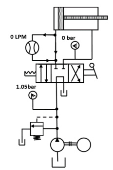
Fig. Application of tandem neutral position in 4/3 DCV
Application of 4/3 DCV (float neutral) for controlling a bidirectional motor
- The pressure port is blocked so that the pump flow is forced over the pressure relief valve. Because both the outlets are connected to the tank, the motor floats or spins freely when the DCV is in the neutral.
- This type is used in motor circuits because it allows the motor to spin to a stop when the valve is shifted to the neutral.
- This is often preferable to shifting to a closed position because motors often build up a great deal of momentum.
- Shifting the valve closed in this situation causes a large pressure hike in the outlet line because the motor tends to keep spinning and tries to push the fluid into its outlet. This is known as shifting shock.
- Float neutrals are often desirable for cylinder circuits in some applications.
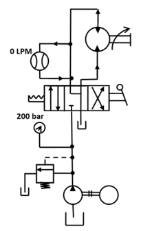
Fig. Application of Float neutral position in 4/3 DCV
Application of 4/3 DCV (open neutral) for controlling a double-acting cylinder
- Flow always follows the path of least resistance, so the pump flow goes back to the tank.
- Because the outlets are also connected to the tank, the cylinder floats when this valve is in neutral.
- This is desirable in a circuit in which some external force must position the cylinder when in the neutral.
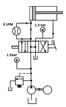
Fig. Application of open neutral position in 4/3 DCV
Application of 4/3 DCV (regenerative neutral) for controlling a double-acting cylinder
- A regenerative neutral is considerably different in its function than other types. A regenerative term is used to describe a system in which the waste is feedback into the system to supplement the input power.
- In this neutral, the pressure port is connected to both outlets and the tank port is blocked.
- When this valve is shifted to the neutral, the pump pressure is applied to both sides of the piston.
- Because the piston area in the rod side of the cylinder is smaller than that on the blindside, there is a net force applied to extend the piston rod.
- As the piston extends, it forces the outlet flow from the rod side back into the valve, where it combines with the pump flow and goes to the blind end of the cylinder.
- This causes a considerable increase in cylinder speed. This is the purpose of the regenerative neutral that instead of sending the return flow back to the tank, sends it into the inlet side of the cylinder, thereby increasing its speed.
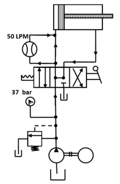
Fig. Application of regenerative neutral position in 4/3 DCV
- Flow-control valves, as the name suggests, control the rate of flow of a fluid through a hydraulic circuit.
- Flow-control valves accurately limit the fluid volume rate from a fixed displacement pump to or from branch circuits.
- Their function is to provide velocity control of linear actuators, or speed control of rotary actuators.
Functions of Flow-Control Valves:
- Regulate the speed of linear and rotary actuators
- Regulate the power available to the sub-circuits by controlling the flow to them
- Proportionally divide or regulate the pump flow to various branches of the circuit.
Classification of Flow-Control Valves
Flow-control valves can be classified as follows:
1. Non-pressure compensated.
2. Pressure compensated.
3.7.1Non-Pressure-Compensated Flow Control Valve
- Non-pressure-compensated flow-control valves are used when the system pressure is relatively constant and motoring speeds are not too critical.
- The operating principle behind these valves is that the flow through an orifice remains constant if the pressure drop across it remains the same. In other words, the rate of flow through an orifice depends on the pressure drop across it.
- The inlet pressure remains constant. Therefore, the variation in pressure occurs at the outlet that is defined by the workload.
- The speed of the piston cannot be defined accurately using non-pressure-compensated flow-control valves when the working load varies.
The schematic diagram of the non-pressure-compensated needle-type flow-control valve is shown in Fig.
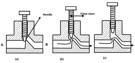
Fig. Needle-type Non-pressure Compensated Flow Control Valve
(a) Fully Closed (b) Partially Opened (c) Fully Opened
- It is the simplest type of flow-control valve.
- It consists of a screw (and needle) inside a tube-like structure.
- It has an adjustable orifice that can be used to reduce the flow in a circuit.
- The size of the orifice is adjusted by turning the adjustment screw that raises or lowers the needle.
- For a given opening position, a needle valve behaves as an orifice.
Sometimes needle valves come with an integrated check valve for controlling the flow in one direction only.
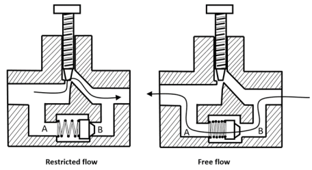
Fig. Flow Control Valve with an integrated Check Valve
- The check valve permits easy flow in the opposite direction without any restrictions.
- Only the flow from A to B is controlled using the needle.
- In the other direction (B to A), the check valve permits unrestricted fluid flow.
3.7.2Pressure Compensated Flow Control Valve
- Pressure-compensated flow-control valves overcome the difficulty caused by non-pressure compensated valves by changing the size of the orifice in relation to the changes in the system pressure.
- This is accomplished through a spring-loaded compensator spool that reduces the size of the orifice when pressure drop increases.
- Once the valve is set, the pressure compensator acts to keep the pressure drop nearly constant.
- It works on a kind of feedback mechanism from the outlet pressure.
- This keeps the flow through the orifice nearly constant.
Schematic diagram of a pressure compensated flow-control valve is shown in Fig
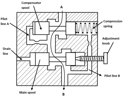
Fig. Pressure Compensated Flow Control Valve
- A pressure-compensated flow-control valve consists of the main pool and a compensator spool. The adjustment knob controls the main spool’s position, which controls the orifice size at the outlet. The upstream pressure is delivered to the valve by the pilot line A.
- Similarly, the downstream pressure is ported to the right side of the compensator spool through the pilot line B.
- The compensator spring biases the spool so that it tends toward the fully open position.
- If the pressure drop across the valve increases, that is, the upstream pressure increases relative to the downstream pressure, the compensator spool moves to the right against the force of the spring.
- This reduces the flow that in turn reduces the pressure drop and tries to attain an equilibrium position as far as the flow is concerned.
- In the static condition, the hydraulic forces hold the compensator spool in balance, but the bias spring forces it to the far right, thus holding the compensator orifice fully open.
- In the flow condition, any pressure drop less than the bias spring force does not affect the fully open compensator orifice, but any pressure drop greater than the bias spring force reduces the compensator orifice.
- Any change in pressure on either side of the control orifice, without a corresponding pressure change on the opposite side of the control orifice, moves the compensator spool.
- Thus, a fixed differential across the control orifice is maintained at all times. It blocks all flow in excess of the throttle setting.
- As a result, flow exceeding the preset amount can be used by other parts of the circuit or return to the tank via a pressure-relief valve.

Fig. Graphical Symbol of pressure compensated flow control valve
3.7.3Pressure and Temperature Compensation in Flow Control Valve
- The performance of the flow-control valve is also affected by temperature changes which change the viscosity of the fluid.
- Therefore, often flow-control valves have temperature compensation.
- When the temperature increases, the viscosity of oil decreases, this leads to increased velocity, thus increased flow.
- Now to keep the flow constant, the flow area must be reduced.
- This is achieved by using a special alloy rod, which expands and contracts on even small variation in temperature.

Fig. Symbol of Pressure and temperature compensated flow control valve
Pressure-control valves are used in hydraulic systems to control actuator force (force = pressure × area) and to determine and select pressure levels at which certain machine operations must occur.
Pressure controls are mainly used to perform the following system functions:
- Limiting maximum system pressure at a safe level.
- Regulating/reducing pressure in certain portions of the circuit.
- Unloading system pressure.
- Assisting the sequential operation of actuators in a circuit with pressure control.
- Any other pressure-related function by virtue of pressure control.
- Reducing or stepping down pressure levels from the main circuit to lower pressure in a sub-circuit.
3.8.1Pressure Relief Valve
Pressure-relief valves limit the maximum pressure in a hydraulic circuit by providing an alternate path for fluid flow when the pressure reaches a preset level.
A relief valve opens and bypasses fluid when pressure exceeds its setting. The valve then closes again when pressure falls. This means that a relief valve can bypass fluid anytime, or all the time, without intervention by maintenance.
The schematic diagram of the simple relief valve is shown in Fig.
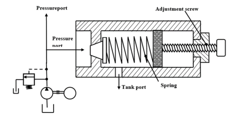
Fig. Simple Pressure Relief Valve

Fig. 3D view of Pressure Relief Valve
- It is normally a closed valve whose function is to limit the pressure to a specified maximum value by diverting the pump flow back to the tank.
- A poppet is held seated inside the valve by a heavy spring.
- When the system pressure reaches a high enough value, the poppet is forced off its seat.
- This permits flow through the outlet to the tank as long as this high-pressure level is maintained.
- Note the external adjusting screw, which varies spring force and, thus, the pressure at which the valve begins to open.
- An important function of a pressure-relief valve is to limit the force or torque produced by hydraulic cylinders or motors.
- The main advantage of direct-acting relief valves over pilot-operated relief valves is that they respond very rapidly to pressure buildup.
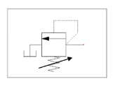
Fig. Symbol of Simple Pressure Relief Valve
3.8.2Compound Pressure Relief Valve (pilot-operated Pressure Relief Valve)
A pilot-operated pressure-relief valve consists of a small pilot relief valve and main relief valve as shown in Fig

Fig. Compound Pressure Relief Valve
- The pilot-operated pressure-relief valve has a pressure port that is connected to the pump line and the tank port is connected to the tank. The pilot relief valve is a poppet type.
- The main relief valve consists of a piston and a stem. The main relief piston has an orifice drilled through it.
- The piston has equal areas exposed to pressure on top and bottom and is in a balanced condition due to equal force acting on both sides.
- It remains stationary in the closed position. The piston has a light bias spring to ensure that it stays closed.
- When the pressure is less than that of the relief valve setting, the pump flow goes to the system. If the pressure in the system becomes high enough, it moves the pilot poppet off its seat.
- A small amount of flow begins to go through the pilot line back to the tank.
- Once flow begins through the piston orifice and pilot line, a pressure drop is induced across the piston due to the restriction of the piston orifice.
- This pressure drop then causes the piston and stem to lift off their seats and the flow goes directly from the pressure port to the tank.
The advantages of pilot-operated pressure-relief valves over direct-acting pressure-relief valves are as follows:
1. Pilot-operated pressure-relief valves are usually smaller than direct-acting pressure-relief valves for the same flow and pressure settings.
2. They have a wider range for the maximum pressure settings than direct-acting pressure relief valves.
3. They can be operated using a remote while direct-acting pressure-relief valves cannot.
3.8.3Pressure Reducing Valve
This type of valve (which is normally open) is used to maintain reduced pressures in specified locations of hydraulic systems. It is actuated by downstream pressure and tends to close as this pressure reaches the valve setting.
A schematic diagram of the pressure reducing valve is shown in Fig.

Fig. Pressure Reducing Valve
- A pressure-reducing valve uses a spring-loaded spool to control the downstream pressure.
- If the downstream pressure is below the valve setting, the fluid flows freely from the inlet to the outlet.
- Note that there is an internal passageway from the outlet which transmits outlet pressure to the spool end opposite the spring.
- When the outlet (downstream) pressure increases to the valve setting, the spool moves to the right to partially block the outlet port. Just enough flow is passed to the outlet to maintain its preset pressure level.
- Reverse free flow through the valve is only possible if the pressure exceeds the valve setting. The valve then closes, thus making reverse flow impossible. Therefore, pressure-reducing valves are often equipped with a check valve for reverse free flow.
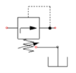
Fig. Symbol of Pressure Reducing Valve
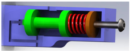
Fig. 3D view of pressure reducing valve
The figure shows an application for a pressure-reducing valve.
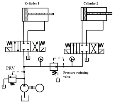
Fig. Application of Pressure Reducing Valve
Here two cylinders are connected in parallel. The circuit is designed to operate at a maximum pressure p1, which is determined by the relief valve setting. This is the maximum pressure at which cylinder 1 operates. By the function of the machine, cylinder2 is limited to pressurep2 (p2<p1).This can be accomplished by placing a pressure-reducing valve in the circuit in the location shown in Fig. 1.9. If the pressure in the cylinder2 circuit rises above p2, the pressure-reducing valve closes partially to create a pressure drop across the valve. The valve then maintains the pressure drop so that the outlet pressure is not allowed to rise above the p2 setting.
3.8.4Sequence Valve
A sequence valve is a pressure control valve that is used to force two actuators to operate in sequence. They are similar to the pressure-relief valve.
Schematic diagram of the sequence valve is shown in Fig
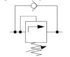
Fig. Symbol of Sequence Valve
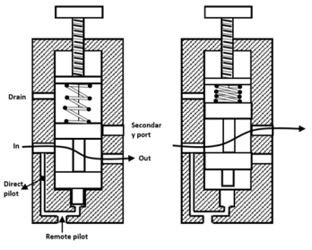
Fig. Sequence Valve
The hydraulic circuit is shown in Fig. Below is an example of an application of a sequence valve in which a clamp cylinder extends first to hold a workpiece and then a second cylinder extends to bend the workpiece in the desired shape.

Fig. Application of sequence valve
- In this circuit, two cylinders are connected in parallel. Without the sequence valve, these cylinders would extend together as they are both unloaded.
- For this circuit to function properly, the clamp cylinder must extend completely before the bending cylinder begins to extend.
- When the clamp cylinder extends completely, the pressure rises and opens the sequence valve, thus allowing the bending cylinder to extend.
- The sequence valve must be set high enough so that it opens only after the complete extension of the clamp cylinder.
- During the retraction of cylinders, the check valve allows the sequence valve to be bypassed.
- The sequence valve has no effect on the circuit in this situation. Both cylinders retract together because both are unloaded and split the pump flow.
3.8.5Unloading Valve
Unloading valves are pressure-control devices that are used to dump excess fluid to the tank at little or no pressure.
Schematic diagram of the unloading valve is shown in Fig

Fig. Unloading Valve
- In an unloading valve; the unloading spool receives a signal through the remote-pilot port when the pressure in the working circuit goes above its setting.
- At the same time, pressure on the spring-loaded ball in the pilot section starts to open it.
- Pressure drop on the front side of the unloading spool lowers back force and pilot pressure from the high-pressure circuit forces the spring-loaded ball completely off its seat.
- When the pressure falls approximately 15% below the pressure set in the pilot section, the spring-loaded ball closes and pushes the unloading spool back for the next cycle.
- An unloading valve requires no electric signals.
The figure shows the application of the unloading valve in a punching press.

Fig. Application of unloading valve in a punching press
3.8.6Back Pressure and Counter Balance Valve
Schematic diagram of the counterbalance valve is shown in Fig
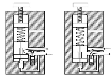
Fig. Counterbalance Valve
These normally closed valves are primarily used to maintain a back pressure on a vertical cylinder to prevent it from falling due to gravity. They are used to prevent a load from accelerating uncontrollably. Hence Counter Balance Valve is primarily used as Back Pressure Valve.
- Valve’s primary port is connected to the cylinder’s rod end and the secondary port to the directional control valve. The pressure setting is slightly higher than that required to keep the load from free-falling.
- When the pressurized fluid flows to the cylinder’s cap end, the cylinder extends, increasing pressure in the rod end and shifting the main spool in the counterbalance valve.
- This creates a path that permits the fluid to flow through the second port via the directional control valve and to the reservoir. As the load is raised, the integral check valve opens to allow the cylinder to retract freely.
- If it is necessary to relieve back pressure at the cylinder and increase the force at the bottom of the stroke, the counterbalance valve can be operated remotely.
- Counterbalance valves are usually drained internally.
- When the cylinder extends, the valve must open and its secondary port should be connected to the reservoir.
- When the cylinder retracts, it matters little that load pressure is felt in the drain passage because the check valve bypasses the valve’s spool.
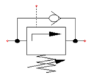
Fig. Symbol of the Counterbalance valve
Counterbalance valves are commonly used to counterbalance weight or external force or counteract a weight such as a platen or a press and keep it from freefalling.
The figure illustrates the use of a counterbalance or back-pressure valve to keep a vertically mounted cylinder in the upward position while the pump idles, that is, when the DCV is in its center position. During the downward movement of the cylinder, the counterbalance valve is set to open at slightly above the pressure required to hold the piston up (a check valve does not permit flow in this direction).
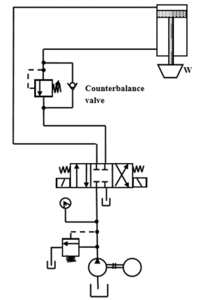
Fig. Application of Counterbalance valve
Servo valves are a close relative of the proportional valve and are based on an electrical torque motor which produces a small deflection proportional to the electrical current through its coil. They commonly use feedback between the main and pilot spools to give precise control. A typical device is shown in Figure.
This consists of a small pilot spool connected directly to the torque motor. The pilot spool moves within a sliding sleeve, mechanically linked to the main spool.
The fight-hand end of the main spool is permanently connected to the pilot pressure line, but because of the linkage rod, its area is reduced to an annulus of area A. The pressure at the left-hand end of the spool is controlled by the pilot valve. There is no area restriction at this end, and the valve is designed such that the spool has an area of 2A.
The mechanical linkage between the main spool and pilot sleeve controls the flow of fluid between the pilot valve and main valve, and hence controls the pressure at the left-hand end of the main pool.
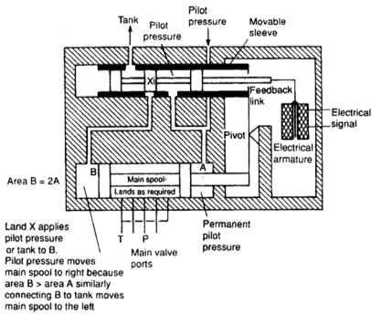
Fig. Servo valve
Servo valves are generally used as part of an external control loop in a feedback control system. The principle of a feedback control system is shown in Figure, where some plant variable (velocity or position, for example) is to be controlled. The plant variable is measured by a suitable transducer and electronically compared with the desired value to give an error signal. This is amplified and used as the control signal for the servo valve.

Fig. Feedback Control System
- Cartridge valve is a two-position valve, four valves are needed to provide directional control.
- Cartridge valves consist of a valve shell that can be mounted in a standard recess in a valve block or manifold. Cartridge valves eliminate expensively and potentially leaking pipework and connectors.
- The valve shell or body has two main ports (A and B) that are connected or separated by a poppet or a spool.
- The poppet-type cartridge valve is a check valve that can be pilot-operated in a number of ways, whereas the spool-type cartridge valve is used as a variable restrictor that is either normally open or closed by the action of the control or vice versa. The actions of the two types of cartridge valves are completely different.
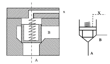
Fig. Poppet type Cartridge Valve
Cartridge valves can be used as follows:
1. Leak-proof direction control valve.
2. Check the valve to obtain unidirectional flow.
3. Throttle valve to control and limit the rate of flow.
- A proportional valve is a valve that produces an output (direction, pressure, flow) that is proportional to an electronic control input.
- Proportional control valves can be operated easily using a solenoid.
- They are very quick in their operation and thus give rise to pressure and flow surges in the fluid power control units.
- The advantage of these valves is that they give greater flexibility in the system design and operation. They also decrease fluid power circuit complexity especially for processes requiring multiple speed or force outputs.
- The electrical control to the proportional valve normally uses a variable current rather than a variable voltage.
- If a voltage control system is adopted, any variation in coil resistance caused by temperature change will result in a change in current. This problem is eliminated by using a current control system.
- It is possible to control a force electrically. By applying the force to a compression spring, its deflection can be controlled.
- If the spool in a valve (as in Fig) is acted on by a spring at one end and a proportional solenoid on the other, the orifice size can be varied along with the control current.
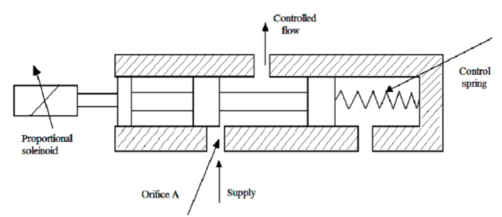
Fig. Proportional Control Valve
A brake valve performs the same function as a counterbalance valve, but it is designed to overcome a key disadvantage of hydraulic power loss due to pressure drop across the counterbalance valve.
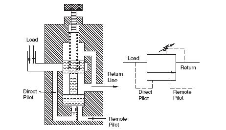
Fig. Brake Valve
As shown in the functional diagram in Fig, a brake valve has an internal pilot passage and a remote pilot passage. Suppose the spring is set for 1000 psi. When the pressure at the internal pilot reaches 1000 psi, the piston pushes the spool upward to open the valve.
The area of the piston is much less than the area of the bottom of the spool. A typical area ratio might be 10:1. The remote pilot applies pressure directly to the bottom of the spool; consequently, only 100 psi is required to compress the spring and open the valve. The pressure required to open the valve is 1000 psi at the internal pilot and 100 psi at the remote pilot.
References:
1. Pipenger J.J, Industrial Hydraulics, McGraw Hill
2. Pinches, Industrial Fluid Power, Prentice Hall
3. Yeaple, Fluid Power Design Handbook
4. Andrew A. Parr, Hydraulics and Pneumatics, Elsevier Science and Technology Books
5. ISO - 1219, Fluid Systems and components, Graphic Symbols
6. Standard Manufacturer’s Catalogues