Unit - 4
Hydraulic Circuits and Contamination Control
The figure shows that the control of a single-acting, spring return cylinder using a three-way two-position manually actuated, spring offset direction-control valve (DCV).

Fig. Control of Single Acting Cylinder
- In the spring offset mode, full pump flow goes to the tank through the pressure-relief valve (PRV).
- The spring in the rod end of the cylinder retracts the piston as the oil from the blank end drains back into the tank.
- When the valve is manually actuated into its next position, pump flow extends the cylinder.
- After the full extension, the pump flow goes through the relief valve.
- Deactivation of the DCV allows the cylinder to retract as the DCV shifts into its spring offset mode.
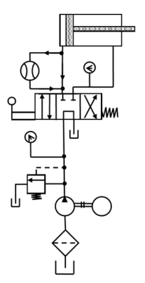
Fig. Simple Reciprocating Cylinder Circuit
The circuit diagram shows the reciprocating of a double-acting cylinder.
The control of a double-acting hydraulic cylinder is described as follows:
- When the 4/3 valve is in its neutral position (tandem design), the cylinder is hydraulically locked and the pump is unloaded back to the tank.
- When the 4/3 valve is actuated into the flow path, the cylinder is extended against its load as oil flows from port P through port A. Oil in the rod end of the cylinder is free to flow back to the tank through the four-way valve from port B through port T.
- When the 4/3 valve is actuated into the right-envelope configuration, the cylinder retracts as oil flows from port P through port B. Oil in the blank end is returned to the tank via the flow path from port A to port T.
At the end of the stroke, there is no system demand for oil. Thus, the pump flow goes through the relief valve at its pressure level setting unless the four-way valve is deactivated.
The figure shows a regenerative circuit that is used to speed up the extending speed of a double-acting cylinder.

Fig. Regenerative Circuit
- The pipelines to both end of the hydraulic cylinder are connected in parallel and one of the ports of the 4/3 valve is blocked by simply screwing a threaded plug into the port opening.
- During retraction stroke, the 4/3 valve is configured to the right envelope.
- During this stroke, the pump flow bypasses the DCV and enters the rod end of the cylinder. Oil from the blank end then drains back to the tank through the DCV.
- When the DCV is shifted into its left-envelope configuration, the cylinder extends as shown in Fig.
- The speed of extension is greater than that for a regular double-acting cylinder because the flow from the rod end regenerates with the pump flow QP to provide a total flow rate QT.
The main function of this circuit is to increase the speed of extending stroke.
In hydraulic operations, it is necessary to control the speed of the actuator to control the force, power, timing, and other factors of the operation. Actuator speed control is achieved by controlling the rate of flow into or out of the cylinder.
There are two methods of controlling the speed of a hydraulic circuit is either by controlling the flow going into the cylinder or by controlling the flow out of the cylinder. To achieve this, Flow control valves are used.
The commonly used methods of speed control are:
- Meter-in Circuit
- Meter-out Circuit
- Bleed-off Circuit
4.4.1 Meter-in Circuit
The figure shows a meter-in circuit with control of extending stroke.
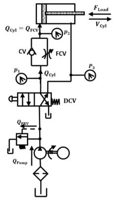
Fig. Meter-in Circuit
- The inlet flows into the cylinder is controlled using a flow-control valve.
- In the return stroke, however, the fluid can bypass the needle valve and flow through the check valve, and hence the return speed is not controlled.
- This implies that the extending speed of the cylinder is controlled whereas the retracing speed is not.
- Similarly, the meter-in circuit can also be used to control the return stroke by placing the flow control valve and check valve to the inlet port during the return stroke.
4.4.2 Meter-out Circuit
The figure shows a meter-out circuit for flow control during the extend stroke.
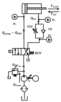
Fig. Meter-out Circuit
- When the cylinder extends, the flow coming from the pump into the cylinder is not controlled directly.
- However, the flow out of the cylinder is controlled using the flow-control valve (metering orifice).
- On the other hand, when the cylinder retracts, the flow passes through the check valve unopposed, bypassing the needle valve.
- Thus, only the speed during the extended stroke is controlled.
- Similarly, the meter-out circuit can also be used to control the return stroke by placing the flow control valve and check valve to the outlet port during the return stroke.
Both the meter-in and meter-out circuits mentioned above perform the same operation (control the speed of the extending stroke of the piston), even though the processes are exactly opposite to one another.
4.4.3 Bleed-off Circuit
Compared to meter-in and meter-out circuits, a bleed-off circuit is less commonly used. The figure shows a bleed-off circuit with extend stroke control.

Fig. Bleed-off Circuit for the inlet to the cylinder
- In this type of flow control, an additional line is run through a flow-control valve back to the tank.
- To slow down the actuator, some of the flow is bled-off through the flow-control valve into the tank before it reaches the actuator.
- This reduces the flow into the actuator, thereby reducing the speed of the extend stroke.
- The main difference between a bleed-off circuit and a meter-in/meter-out circuit is that in a bleed-off circuit, opening the flow-control valve decreases the speed of the actuator, whereas, in the case of a meter-in/meter-out circuit, it is the other way around.
- By placing the flow-control valve to the outlet port in a similar manner, the return stroke can also be bleed-offed.
The cylinder can also be bleed-offed in both direction as shown below
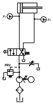
Fig. Bleed-off Circuit for both directions
4.4.4 Speed Control of Hydraulic Motor
The figure shows the speed control circuit of a hydraulic motor using a pressure-compensated FCV.

Fig. Speed Control of Hydraulic Motor
The operation is as follows:
- In a spring-centered position of the tandem four-way valve, the motor is hydraulically blocked.
- When the valve is actuated to the left envelope, the motor rotates in one direction. Its speed can be varied by adjusting the throttle of the FCV. Thus, the speed can be infinitely varied and the excess oil goes through the PRV.
- When the valve is deactivated, the motor stops suddenly and becomes locked.
- When the right envelope is in operation, the motor turns in the opposite direction. The PRV provides overload protection if, for example, the motor experiences an excessive torque load.
Hydraulic cylinders can be operated sequentially using a sequence valve. The figure shows that two sequence valves are used to sequence the operation of two double-acting cylinders.

Fig. Sequencing Circuit
- When the DCV is actuated to its right-envelope mode, the bending cylinder (B) retracts fully and then the clamp cylinder (A) retracts.
- This sequence of cylinder operation is controlled by sequence valves. This hydraulic circuit can be used in a production operation such as drilling.
- Cylinder A is used as a clamp cylinder and cylinder B as a drill cylinder.
- Cylinder A extends and clamps a workpiece. Then cylinder B extends to drive a spindle to drill a hole.
- Cylinder B retracts the drill spindle and then cylinder A retracts to release the workpiece for removal.
In industry, there are instances when a large mass must be moved, and it is not feasible to move it with just one cylinder. In such cases, we use two or more cylinders to prevent a moment or moments that might distort and damage the load.
For example, in the press used for molding and shearing parts, the platen used is very heavy. If the platen is several meters wide, it has to be of very heavy construction to prevent the damage when it is pressed down by a single cylinder in the middle. It can be designed with less material if it is pressed down with two or more cylinders. These cylinders must be synchronized.
There are two ways that can be used to synchronize cylinders:
Parallel and series.
4.6.1 Synchronization of cylinders in parallel
- When the two cylinders are identical, the loads on the cylinders are identical, and then extension and retraction are synchronized.
- If the loads are not identical, the cylinder with a smaller load extends first.
- Thus, the two cylinders are not synchronized. Practically, no two cylinders are identical, because of packing (seals) friction differences. This prevents cylinder synchronization for this circuit.
4.6.2 Synchronization of cylinders in series
- During the extending stroke of cylinders, fluid from the pump is delivered to the blank end of cylinder 1.
- As cylinder 1 extends, fluid from its rod end is delivered to the blank end of cylinder 2 causing the extension of cylinder 2.
- As cylinder 2 extends, fluid from its rod end reaches the tank. For two cylinders to be synchronized, the piston area of cylinder 2 must be equal to the difference between the areas of piston and rod for cylinder 1.
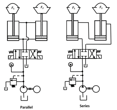
Fig. Synchronization Circuit
- In this circuit, full flow from the pump is allowed to the cap end through the directional valve (3) for a fast approach and the rod end oil freely passes through the normally open deceleration valve back to the tank.
- Near about the end of the stroke, a cam depresses a roller attached to the deceleration valve spool, and therefore the valve shifts blocking the flow from the rod end.
- The flow now has only one pathway back to the tank and that is through FCV (4).
- The approach speed is now governed by the setting of this valve. During piston retraction stroke, full flow is allowed to the rod end through the check valve (6).
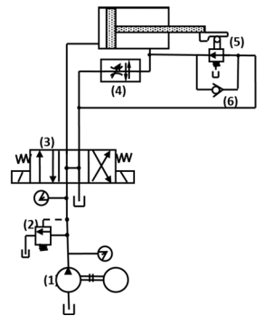
Fig. Traverse and feed circuit
The sequence valve can also be used to reciprocate the cylinder automatically.
The hydraulic circuit shown in Fig produces continuous reciprocation of a double-acting cylinder using two sequence valves.

Fig. Automatic cylinder reciprocating circuit
- Each sequence valve senses the completion of a stroke by the corresponding build-up pressure.
- Each check valve and the corresponding pilot line prevent the shifting of the four-way valve until the particular stroke of the cylinder is completed.
- The check valves are needed to allow pilot oil to leave either end of the DCV while the pilot pressure is applied to the opposite end. This permits the spool of the DCV to shift as required.
Fail-safe circuits are those designed to prevent injury to the operator or damage to the equipment. In general, they prevent the system from accidentally falling on an operator and also prevent overloading of the system.
In the following sections we shall discuss two fail-safe circuits:
One is protection from inadvertent cylinder extension and the other is fail-safe overload protection.
4.9.1 Protection from inadvertent cylinder extension:
The figure shows a fail-safe circuit that is designed to prevent the cylinder from accidentally falling in the event when a hydraulic line ruptures or a person inadvertently operates the manual override on the pilot-actuated DCV when the pump is not working.

Fig. Fail-safe circuit – inadvertent cylinder extension
- To lower the cylinder, pilot pressure from the blank end of the piston must pilot open the check valve to allow the oil to return through the DCV to the tank.
- This happens when the push button is actuated to permit the pilot pressure actuation of DCV or when the DCV is directly manually actuated when the pump operates.
- The pilot-operated DCV allows free flow in the opposite direction to retract the cylinder when this DCV returns to its offset mode.
4.9.2 Fail-Safe System with Overload Protection:
The figure shows a fail-safe system that provides overload protection for system components.
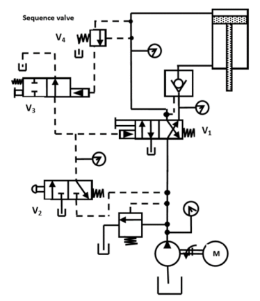
Fig. Fail-safe circuit – overload protection
A counterbalance valve is applied to create back pressure or cushioning pressure on the underside of a vertically moving piston to prevent the suspended load from free-falling because of gravity while it is still being lowered.
Valve operation:
- Lowering:
The pressure setting on the counterbalance valve is set slightly higher than the pressure required to prevent the load from free falling. Due to this backpressure in line A, the actuator piston must force down when the load is being lowered. This causes the pressure in line A to increase, which raises the spring opposed spool, thus providing a flow path to discharge the exhaust flow from line A to the DCV and then to the tank. The spring-controlled discharge orifice maintains back pressure in line A during the entire downward piston stroke.
2. Lifting:
As the valve is normally closed, flow in the reverse direction (from port B to port A) cannot occur without a reverse free-flow check valve. When the load is raised again, the internal check valve opens to permit flow for the retraction of the actuator.
3. Suspension:
When the valve is held in suspension, the valve remains closed. Therefore, its pressure setting must be slightly higher than the pressure caused by the load. Spool valves tend to leak internally under pressure. This makes it advisable to use a pilot-operated check valve in addition to the counterbalance valve if a load must be held in suspension for a prolonged time.
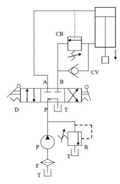
Fig. Counterbalance circuit
- A check valve blocks flow in one direction but allow free flow in the opposite direction.
- A pilot-operated check valve permits flow in the normally blocked opposite direction when pilot pressure is applied at the pilot pressure port of the valve.
- Pilot-operated check valves are used to lock the cylinder so that its piston cannot be moved by an external force.
- The cylinder can be extended and retracted by the DCV.
- If regular check valves are used, the cylinder could not extend or retract.
- The external force acting on the piston rod does not move the piston in either direction thus locking the cylinder.

Fig. Actuator (Cylinder) locking Circuit
The figure shows a hydraulic circuit to unload a pump using an unloading valve.
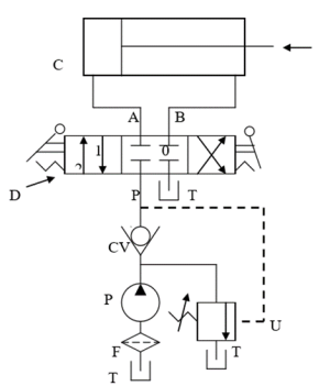
Fig. Pump unloading circuit
- When the cylinder reaches the end of its extension stroke, the pressure of oil rises because the check valve keeps the high-pressure oil.
- Due to high-pressure oil in the pilot line of the unloading valve, it opens and unloads the pump pressure to the tank.
- When the DCV is shifted to retract the cylinder, the motion of the piston reduces the pressure in the pilot line of the unloading valve.
- This resets the unloading valve until the cylinder is fully retracted.
- When this happens, the unloading valve unloads the pump due to high-pressure oil.
- Thus, the unloading valve unloads the pump at the ends of the extending and retraction strokes as well as in the spring-centered position of the DCV.
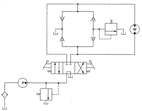
Fig. Hydraulic Motor Braking Circuit
- For, the position of DCV spool-I the flow of the oil takes place through DCV. This oil will directly go to the motor, because of which motor starts rotating.
- The discharged oil from the motor to the tank through DCV.
- In the second condition, Flow will go through DCV and will enter the motor which causes it to rotate in the opposite direction to that of above.
- The discharge of the motor will go to the tank through DCV.
- The third and most important thing happens when the spool position is suddenly changed to III from I or II. In this case, the flow is suddenly stopped and because of higher inertia of machine coupled to the motor, the motor starts to rotate even tough flow has stopped. This condition can damage the component.
- The above case can be avoided. Due to the pump action of the motor, the pressure of oil in the line increases as there is no way out for the oil. The pressurized oil opens one of the check valves.
- The pressure relief is set at a higher-pressure level at its opening.
- This valve will not get open, hence it blocks the lines and stops the motor.
- Ideally, hydraulic oil should create a lubricating film to keep precision parts separated.
- To reduce wear, this film should be thick enough to completely fill the clearance between moving parts.
- The actual thickness of a lubricating film depends on fluid viscosity, applied load, and the relative speed of the two surfaces.
- If the contamination particle is larger than the clearance between the surfaces, the result is interference. Friction is increased and damage results.
- This damage introduces more contaminant particles.
- Therefore, contaminant size should be kept smaller than the clearance, and the number of these particles reduced as much as possible.
4.14.1 Types of contaminants
- Particle contaminants
Particle sizes are generally measured in micrometers or microns. Some examples of microns: Grain of salt 100 microns, human hair 70 microns, lower limit of visibility 40 microns, milled flour 25 microns, average bacteria 2 microns. Note that most damage-causing particles in hydraulic or lubrication systems are smaller than 14µm micrometers, so they cannot be seen.
2. Water
The most common chemical contaminant in hydraulic systems is water. The presence of water in hydraulic oil can have wide-ranging effects on system components because of its effect on the physical and chemical properties of hydraulic oil. Rust in tanks, reduced lubrication characteristics resulting in accelerated metal surface wear are some of the most obvious physical results of excessive water, however, the effects could be as diverse as the jamming of components due to ice crystals at low temperatures.
3. Air
The air in a hydraulic system can exist in either a dissolved or entrained (undissolved, or free) state. Dissolved air may not pose a problem, providing it stays in solution. When a liquid contains undissolved air, problems can occur as it passes through system components. There can be pressure changes that compress the air and produce a large amount of heat in small air bubbles. This compressibility of air means that control of the system is lost. Air bubbles and frothing in the oil reservoir can cause major damage to pumps or it can also cause the oil to “boil” out of the tank.
4. Heat
Excessive heat in hydraulic systems can also result in additive depletion or chemical changes to the oil.
4.14.2 Sources of contamination in hydraulic systems
In general, there are four main sources of contamination in hydraulic oil.
- “Native” contamination: These are contaminant particles that were left in the system or any of its components during manufacture or repair and include contaminants such as welding slag, machining swarf, pieces of Teflon tape or excessive sealant.
- Contaminated new oil: New oil may not be clean enough for the system (and is generally not clean enough for a modern, high-pressure hydraulic system). The manufacturing process and the subsequent handling and storage introduce contaminants.
- Ingresses contamination: This contamination may enter with air flowing into the reservoir through the breather cap. Water will build up in the oil of a system operating in humid conditions if there is no protection against this built into the reservoir. Another common source is dirt particles riding in on a cylinder rod. No rod seal can prevent the entrance of particles, this can be a major source of contamination on earthmoving equipment operating in extreme conditions. Furthermore, whenever the system is opened in any way such as when a hose is disconnected or fluid is topped up, there is the potential for contamination to ingress.
- Internally generated contamination: Particles removed from the interior surface of the components will circulate in the system until they are removed. Each impact of one of these particles with a surface causes more damage. This phenomenon is known as the wear regeneration cycle. Included in this is contamination from the catastrophic failure of components within the system.
For proper operation and long service life of a hydraulic system, oil cleanliness is of prime importance. Hydraulic components are very sensitive to contamination. The cause of the majority of hydraulic system failures can be traced back to contamination. Hence, the filtration of oil leads to proper operation and long service life of a hydraulic system. Strainers and filters are designed to remove foreign particles from the hydraulic fluid.
The process of removal of contaminants from the oil by use of filters and strainers is called as filtration.
They can be differentiated by the following definitions:
- Filters: They are devices whose primary function is the retention, by some fine porous medium, of insoluble contaminants from the fluid. Filters are used to pick up smaller contaminant particles because they can accumulate them better than a strainer. Generally, a filter consists of fabricated steel housing with an inlet and an outlet. The filter elements are held in position by springs or other retaining devices. Because the filter element is not capable of being cleaned, that is, when the filter becomes dirty, it is discarded and replaced by a new one. Particle sizes removed by filters are measured in microns. The smallest sized particle that can be removed is as small as 1 µm. A strainer is a device whose function is to remove large particles from a fluid using a wire screen. The smallest sized particle that can be removed by a strainer is as small as 0.15 mm or 150 µm.
- Hydraulic strainers: A strainer is a coarse filter. Fluid flows more or less straight through it. A strainer is constructed of a fine wire mesh screen or screening consisting of a specially processed wire of varying thickness wrapped around metal frames. It does not provide as fine a screening action as filters do, but offers less resistance to flow and is used in pump suction lines where pressure drop must be kept to a minimum. A strainer should be as large as possible or wherever this is not practical, two or more may be used in parallel.
4.16.1Types of Filters
1. According to the filtering methods:
- Mechanical filters: This type normally contains a metal or cloth screen or a series of metal disks separated by thin spacers. Mechanical filters are capable of removing only relatively coarse particles from the fluid.
- Absorption filters: These filters are porous and permeable materials such as paper, wood pulp, diatomaceous earth, cloth, cellulose, and asbestos. Paper filters are impregnated with a resin to provide added strength. In this type of filter, the particles are absorbed as the fluid permeates the material. Hence, these filters are used for extremely small particle filtration.
- Adsorbent filters: Adsorption is a surface phenomenon and refers to the tendency of particles to cling to the surface of the filters. Thus, the capacity of such a filter depends on the amount of surface area available. Adsorbent materials used include activated clay and chemically treated paper.
2. According to the size of pores in the material:
- Surface filters: These are nothing but simple screens used to clean oil passing through their pores. The screen thickness is very thin and dirty unwanted particles are collected at the top surface of the screen when the oil passes, for example, strainer.
- Depth filters: These contain a thick-walled filter medium through which the oil is made to flow and the undesirable foreign particles are retained. Much finer particles are arrested and the capacity is much higher than surface filters.
3. According to the location of filters:
- Intake or inline filters (suction strainers)
- Pressure line filters (high-pressure filters)
- Return line filters (low-pressure filters)
4.16.2 Suction Strainers
- These are provided first before the pump to protect the pump against contaminations in the oil as shown in Fig.
- These filters are designed to give a low-pressure drop, otherwise, the pump will not be able to draw the fluid from the tank.
- To achieve a low-pressure drop across the filters, a coarse mesh is used. These filters cannot filter out small particles.
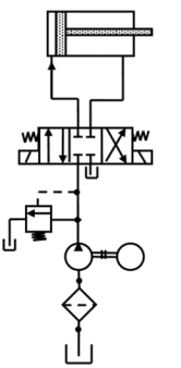
Fig. Suction Filter
Advantages of suction filters:
(a) A suction filter protects the pump from dirt in the reservoir. Because the suction filter is outside the reservoir, an indicator telling when the filter element is dirty can be used.
(b) The filter element can be serviced without dismantling the suction line or reservoir (easy to maintain).
Disadvantages of suction filters:
(a) A suction filter may starve the pump if not sized properly.
4.16.3High-pressure Filter
These are placed immediately after the pump to protect valves and actuators and can be a finer and smaller mesh (Fig). They should be able to withstand the full system pressure. Most filters are pressure line filters.

Fig. Pressure line filters
Advantages of a pressure line filter:
(a) A pressure filter can filter very fine contaminants because the system pressure is available to push the fluid through the element. (b) A pressure filter can protect a specific component from the harm of deteriorating particles generated from an upstream component.
Disadvantages of a pressure line filter:
(a) The housing of a pressure filter must be designed for high-pressure because it operates at full system pressure. This makes the filter expensive.
(b) If pressure differential and fluid velocity are high enough, dirt can be pushed through the element or the element may tear or collapse.
4.16.4 Low-pressure Filters
These filters filter the oil returning from the pressure relief valve or the system, that is, the actuator to the tank (Fig). They are generally placed just before the tank. They may have a relatively high-pressure drop and hence can be a fine mesh. These filters have to withstand low-pressure only and also protect the tank and pump from contamination.
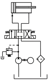
Fig. Return line filter
Advantages of a return line filter:
(a)A return line filter catches the dirt in the system before it enters the reservoir.
(b)The filter housing does not operate under full system pressure and is, therefore, less expensive than a pressure filter.
Disadvantages of a return line filter:
(a) There is no direct protection for circuit components.
(b) In return line full-flow filters, flow surges from discharging cylinders, actuators, and accumulators must be considered when sizing.
The filtration industry uses the ISO 16889 “Multipass Test Procedure” to evaluate filter element performance. During the Multipass Test, fluid is circulated through the circuit under precisely controlled and monitored conditions. The differential pressure across the test element is continuously recorded, as a constant amount of contaminant is injected upstream of the element. Online laser particle sensors determine the contaminant levels upstream and downstream of the test element. This performance attribute (The Beta Ratio) is determined for several particle sizes. Three important element performance characteristics are a result of the Multipass Test:
1. Dirt holding capacity.
2. A pressure differential of the test filter element.
3. Separation or filtration efficiency expressed as a “Beta Ratio”
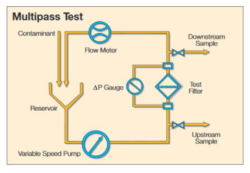
Fig. Multipass Test
Beta Ratio of Filters
Filters are rated according to the smallest size of particles they can trap. Filter ratings are identified by nominal and absolute values in micrometers. A filter with a nominal rating of 10 μm is supposed to trap up to 95% of the entering particles greater than 10 μm in size. The absolute rating represents the size of the largest pore or opening in the filter and thus indicates the largest size particle that could go through. Hence, the absolute rating of a 10 μm nominal size filter would be greater than 10 μm.
A better parameter for establishing how well a filter traps particle is called the beta ratio or beta rating. The beta ratio is determined during laboratory testing of a filter receiving a steady-state flow containing fine dust of selected particle size. The test begins with a clean filter and ends when the pressure drop across the filter reaches a specified value indicating that the filter has reached the saturation point. This occurs when contaminant capacity has been reached.
By mathematical definition, “the beta ratio equals the number of upstream particles of size greater than Nμm divided by the number of downstream particles having a size greater than Nμm where N is the selected particle size for the given filter.”
The ratio is represented by the following equation:

A beta ratio of 1 would mean that no particle above specified N is trapped by the filter.
A beta ratio of 50 means that 50 particles are trapped for everyone that gets through. Most filters have a beta ratio greater than 75

Thus,

References:
1. Pipenger J.J, Industrial Hydraulics, McGraw Hill
2. Pinches, Industrial Fluid Power, Prentice Hall
3. Yeaple, Fluid Power Design Handbook
4. Andrew A. Parr, Hydraulics and Pneumatics, Elsevier Science and Technology Books
5. ISO - 1219, Fluid Systems and components, Graphic Symbols
6. Standard Manufacturer’s Catalogues