Unit - 5
Pneumatics – Components, Control Valves and Circuits
The English word pneumatic and its associate noun pneumatics are derived from the Greek “pneuma” meaning breath or air.
“Pneumatics may be defined as a branch of engineering science which deals with the study of the behavior and application of compressed air.”
“Pneumatics can also be defined as the branch of fluid power technology that deals with the generation, transmission, and control of power using pressurized air.”
5.1.1 Differences between hydraulic and pneumatic systems.
One of the main differences between the two systems is that in pneumatics, the air is compressible. In hydraulics, liquids are not. The other two distinct differences are given below.
Pneumatic Systems
These systems have two main features:
- Pneumatic systems use compressed gas such as air or nitrogen to perform work processes.
- Pneumatic systems are open systems, exhausting the compressed air to the atmosphere after use.
Hydraulic Systems
These systems also have two main features:
- Hydraulic systems use liquids such as oil and water to perform work processes.
- Hydraulic systems are closed systems, recirculating the oil or water after use.
5.1.2 Components of the Pneumatic System
The pneumatic system carries power by employing compressed gas generally air as a fluid for transmitting the energy from an energy-generating source to an energy – use point to accomplish useful work.
The figure shows the simple circuit of a pneumatic system with basic components.
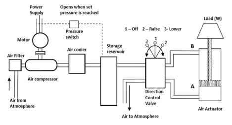
Fig. Components of the Pneumatic System
- Air is drawn from the atmosphere through the air filter and raised to the required pressure by an air compressor.
- As the pressure rises, the temperature also rises and hence air cooler is provided to cool the air with some preliminary treatment to remove the moisture.
- Then the treatment pressurized air needs to get stored to maintain the pressure.
- With the storage reservoir, a pressure switch is fitted to start and stop the electric motor when pressure falls and reached the required level, respectively.
- The cylinder movement is controlled by a pneumatic valve.
- One side of the pneumatic valve is connected to the compressed air and silencers for the exhaust air and the other side of the valve is connected to port A and Port B of the cylinder.
Position of the valve is as follows
- Raise: To lift the weight, the compressed air supply is connected to port A and the port B is connected to the exhaust line, by moving the valve position to the “ Raise”
- Lower: To bring the weight down, the compressed air line is connected to port B and port A is connected to exhaust airline, by moving the valve position to the “lower”
- Off: The weight can be stopped at a particular position by moving the valve to position to the “Off” position. This disconnects the port A and port B from the pressurized line and the retrieval line, which locks the air in the cylinder.
Functions of components
- A pneumatic actuator converts the fluid power into mechanical power to do useful work
- The compressor is used to compress the fresh air drawn from the atmosphere.
- A storage reservoir is used to store a given volume of compressed air.
- Valves are used to control the direction, flow rate, and pressure of compressed air.
- External power supply (Motor) is used to drive the compressor.
- The piping system carries the pressurized air from one location to another.
Advantages of Pneumatic system
- Low inertia effect of pneumatic components due to the low density of air. o Pneumatic Systems are light in weight.
- Operating elements are cheaper and easy to operate
- Power losses are less due to the low viscosity of air
- High output to weight ratio
- Pneumatic systems offer a safe power source in an explosive environment
- Leakage is less and does not influence the systems. Moreover,leakage is not harmful.
Disadvantages of Pneumatic systems
- Suitable only for low-pressure and hence low force applications
- Compressed air actuators are economical up to 50 kN only.
- Generation of the compressed air is expensive compared to electricity
- Exhaust air noise is unpleasant and silence has to be used.
- The rigidity of the system is poor o Weight to pressure ratio is large o Less precise. It is not possible to achieve uniform speed due to the compressibility of air.
- Pneumatic systems are vulnerable to dirt and contamination.
5.1.3 Comparison between Hydraulic and Pneumatic System
Sr. No. | Hydraulic System | Pneumatic System |
1 | It employs a pressurized liquidas fluid | It employs a compressed gas usually air as a fluid |
2 | The oil hydraulics system operates at pressures upto 700 bar. | Pneumatics systems usually operate at 5 to 10 bar. |
3 | Generally designed for closedsystems | Pneumatic systems are usually designed as an open system |
4 | The system gets slow down of leakageoccurs | Leakage does not affect the system much more |
5 | Valve operations are difficult | Easy to operate the valves |
6 | Heavier in weight | Light in weight |
7 | Pumps are used to providepressurized liquids | Compressors are used to provide compressed gas |
8 | The system is unsafe to fire hazards | The system is free from fire hazards |
9 | Automatic lubrication is provided | Special arrangements for lubrication needed. |
“A Compressor is a machine that compresses the air or another type of gas from a low inlet pressure (usually atmospheric pressure) to a higher desired pressure level.”
The compressor increases the pressure of the air by reducing its volume. The work required for increasing the pressure of air is available from the prime mover driving the compressor.Generally, electric motor, internal combustion engine or steam engine, turbine, etc. are used as prime movers.Compressors are similar to fans and blowers but differ in terms of pressure ratios.
5.2.1 Classification
(a) Based on the principle of operation:
Based on the principle of operation compressors can be classified as.
- Positive displacement compressor.
- Non-positive displacement compressors.
I] Positive Displacement Compressors
In positive displacement compressors, the compression is realized by displacement of solid boundary and preventing fluid by solid boundary from flowing back in the direction of the pressure gradient.Due to solid wall displacement, these are capable of providing quite large pressure ratios.Positive displacement compressors can be further classified based on the type of mechanism used for compression.These can be
- Reciprocating type positive displacement compressors
- Rotary type positive displacement compressors.
i]Reciprocating Type Positive Displacement Compressors
- Reciprocating compressors generally, employ the piston-cylinder arrangement where the displacement of the piston in the cylinder causes a rise in pressure.
- Reciprocating compressors are capable of giving large pressure ratios but the mass handling capacity is limited or small.Reciprocating compressors may also be a single-acting compressor or double-acting compressor.
- The single-acting compressor has one delivery stroke per revolution while in double-acting there are two delivery strokes per revolution of the crank shaft.
Ii] Rotary type positive displacement compressors
- Rotary compressors employing positive displacement have a rotary part whose boundary causes positive displacement of fluid and thereby compression.
- Rotary compressors of this type are available in the names as given below:
- Roots blower
- Vane type compressors
- Rotary compressors of the above type are capable of running at higher speed and can handle a large mass flow rate than reciprocating compressors of positive displacement type.
II] Non-positive Displacement Compressors
Non-positive displacement compressors also called a steady flow compressor to use dynamic action of solid boundary for realizing pressure rise.Here the fluid is not contained indefinite volume and subsequent volume reduction does not occur as in case of positive displacement compressors.
Non-positive displacement compressors may be of “axial flow type” or “centrifugal type” depending upon the type of flow in the compressor.
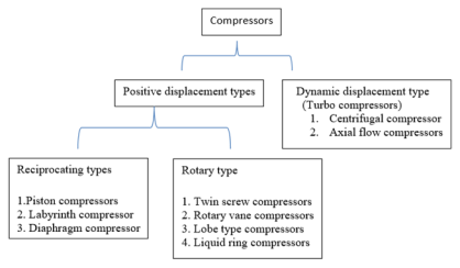
Fig. Classification of Compressor
(b) Based on a number of stages:
Compressors may also be classified on the basis of a number of stages.
Generally, the number of stages depends upon the maximum delivery pressure.Compressors can be single-stage or multistage.Normally maximum compression ratio of 5 is realized in single-stage compressors. For compression ratio more than 5 the multistage compressors are used.
Type values of maximum delivery pressures generally available from a different type of compressor are,
- Single-stage Compressor, for delivery pressure upto 5 bar.
- Two-stage Compressor, for delivery pressure between 5 to 35 bar
- Three-stage Compressor, for delivery pressure between 35 to 85 bar.
- Four stage compressor, for delivery pressure more than 85 bar
(c) Based on Capacity of compressors:
Compressors can also be classified depending upon the capacity of Compressor or air-delivered per unit time.
Typical values of capacity for different compressors are given as;
- Low capacity compressors, having air delivery capacity of 0.15 m3/s or less
- Medium capacity compressors, having air delivery capacity between 0.15 to 5 m3/s.
- High capacity compressors, having air delivery capacity more than 5 m3/s.
(d) Based on the highest pressure developed:
Depending upon the maximum pressure available from compressors they can be classified as low-pressure, medium pressure, high-pressure, and super high-pressure compressors.Typical values of maximum pressure developed for different compressors are as under:
- Low-pressure compressor, having maximum pressure upto 1 bar
- Medium pressure compressor, having maximum pressure from 1 bar to 8 bar
- High-pressure compressor, having maximum pressure from 8 to 10 bar
- Super high-pressure compressor, having maximum pressuremore than 10 bar.
5.3.1 The piston Compressor
The piston compressors are by far the most common type of compressor, and a basic single cylinder form is shown in Figure.
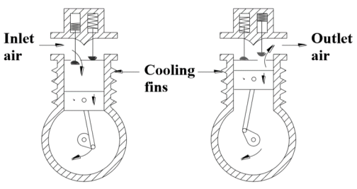
Fig. Single Cylinder The piston Compressor
- As the piston descends during the inlet stroke, the inlet valve opens and the air is drawn into the cylinder.
- As the piston passes the bottom of the stroke, the inlet valve closes and the exhaust valve opens allowing air to be expelled as the piston rises.
- The valves are similar to valves in an internal combustion engine.
- In practice, spring-loaded valves are used, which open and close under the action of air pressure across them.
- The piston compressors go direct from atmospheric to required pressure in a single operation. This is known as a single-stage compressor.
- A single-cylinder compressor gives significant pressure pulses at the outlet port. This can be overcome to some extent by the use of a large receiver, but more often a multi-cylinder compressor is used.
- If the exit pressure is above about 5 bar in a single-acting compressor, the compressed air temperature can rise to over 200~ and the motor power needed to drive the compressor rises accordingly.
- For pressures over a few bars, it is far more economical to use a multistage compressor with cooling between stages. The figure shows an example.
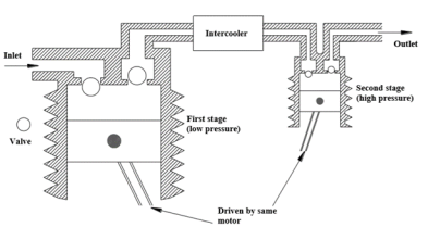
Fig. Multi-stage The piston Compressor
- As cooling (undertaken by a device called an intercooler) reduces the volume of the gas to be compressed at the second stage there is a large energy saving.
- Normally two stages are used for pneumatic pressures of 10 to 15 bar, but multistage compressors are available for pressures up to around 50 bar.
5.3.2 Screw Compressor
One rotary compressor, known as the dry rotary screw compressor, is shown in Figure and consists of two intermeshing rotating screws with minimal (around 0.05 mm) clearance.
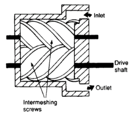
Fig. Screw Compressors
- As the screws rotate, the air is drawn into the housing, trapped between the screws and carried along to the discharge port, where it is delivered in a constant pulse-free stream.
- Screws in this compressor can be synchronized by external timing gears.
- Alternatively, one screw can be driven, the second screw rotated by contact with the drive screw.
- This approach requires oil lubrication to be sprayed into the inlet air to reduce friction between screws and is consequently known as a wet rotary screw compressor.
- Wet screw construction though, obviously introduces oil contamination into the air which has to be removed by later oil separation units.
5.3.3 Rotary Vane Compressor
The vane compressor, shown in Figure operates on similar principles to the hydraulic vane pump.
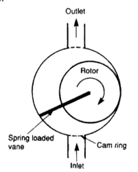
Fig. Vane Compressor
- An unbalanced design is shown, balanced versions can also be constructed.
- Vanes can be forced out by springs or, more commonly, by centrifugal force.
- A single-stage vane compressor can deliver air at up to 3 bar, a much lower pressure than that available with a screw or the piston compressor.
- A two-stage vane compressor with large low-pressure and smaller high-pressure sections linked by an intercooler allows pressures up to 10 bar to be obtained.
5.3.4 Lobe Compressor
The lobe compressor is shown in figure
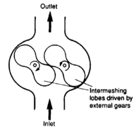
Fig. Lobe Compressor
- Lope Compressor is often used when a positive displacement compressor is needed with high delivery volume but low-pressure (typically 1-2 bar).
- Operating pressure is mainly limited by leakage between rotors and housing.
- To operate efficiently, clearances must be very small and wear leads to a rapid fall inefficiency.
5.3.5 Non-positive Displacement Compressors
- A large volume of air (up to 5000 m 3 min -1) is often required for applications such as pneumatic conveying (where the powder is carried in an airstream), ventilation or where the air itself is one component of a process (e.g. Combustion air for gas/oil burners).
- Pressure in these applications is low (at most a few bars) and there is no need for a positive displacement compressor.
- Large volume low-pressure air is generally provided by dynamic compressors known as blowers.
- They can be subdivided into centrifugal or axial types, shown in Figure.
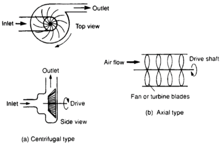
Fig. Non-positive Displacement Compressors
- Centrifugal blowers (Figure a) draw air in then fling it out by centrifugal force. A high shaft rotational speed is needed and the volume to input power ratio is lower than any other type of compressor.
- An axial compressor comprises a set of rotating fan blades as shown in Figure b. These produce very large volumes of air, but at low-pressure (less than one bar). They are primarily used for ventilation, combustion, and process air.
- Output pressures of both types of dynamic compressors can be lifted by multistage compressors with intercoolers between stages.
- Diffuser sections reduce air entry velocity to subsequent stages, thereby converting air kinetic energy to pressure energy.
5.4 Fluid Conditioners in Pneumatic System
“The purpose of the fluid conditioners is to make the compressed air more acceptable and suitable fluid medium for the pneumatic system as well as the operating personal.”
The following fluid conditioners are used in pneumatic systems
1. Air Filters
2. Air Regulators
3. Air Lubricator
5.4.1 Air Filters
The purpose of the air filter is to clean the compressed air of all impurities and any condensate it contains.
The function of air filters
- To remove all foreign matter and allow dry and clean airflow without restriction to the regulator and then to the lubricator
- To condensate and remove water from the air
- To arrest fine particles and all solid contaminants from the air
Filters are available in wide range starting from a fine mesh wire cloth (which strains heavy foreign particles) to elements made of synthetic material (which removes very small particles)
Usually, inline filter elements can remove contaminants in the 5-50 micron range.
The construction of a typical cartridge type filter along with graphical symbols is shown in Figure
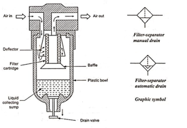
Fig. Typical Air Filter
- It consists of a filter cartridge, Deflector, bowl, water drain valve. The filter bowl is usually made of plastic and transparent.
- For pressure more than 10 bar, the bowl may be made of brass.
- Air enters the inlet port of the air filter through angled louvers. This causes the air to spin as it enters the bowl. The centrifugal action of the rotating air causes the larger pieces of dirt and water particles to be thrown against the inner wall of the filter bowl. These contaminants then flow down into the bottom of the filter bowl.
- A baffle prevents turbulent air from splashing water on to the filter element. The air, which has been pre-cleaned in this way, then passes through the filter element, where the fine dirt particles are filtered out. The size of the dirt particles which can be filtered out depends on the mesh size of the filter element (usually 5-50 microns). The compressed air then exits through the outer port.
- The pressure difference between inlet and outlet will indicate the degree to which the filter element is clogged. Commercially available filters have many additional features like automatic drain facility, coalescing type filter element, service life indicator, etc.
5.4.2 Air Regulator
- The function of the air pressure regulator is to maintain working pressure virtually constant regardless of fluctuations of the line pressure and air consumption.
- When the pressure is too low, it results in poor efficiencies and when the pressure is too high, energy is wasted and equipment’s performance decays faster.
- In a pneumatic system, pressure fluctuations occur due to variation in supply pressure or load pressure.
- It is therefore essential to regulate the pressure to match the requirement of load regardless of variation in supply pressure or load pressure.
- Generally,the pressure is regulated in the pneumatic system in two places.
- At the receiver tank
- In the load circuits
Types of Air Pressure Regulator
There are two types of Pressure regulators
- Diaphragm type regulator
- The piston-type regulator
Diaphragm type regulator is commonly used in the Industrial pneumatic system. There are two types of diaphragm type regulator
- Non- reliving or non-venting type.
- Relieving or venting type
Relieving or Venting Type Pressure regulator
A Relieving type pressure regulator is shown in Figure
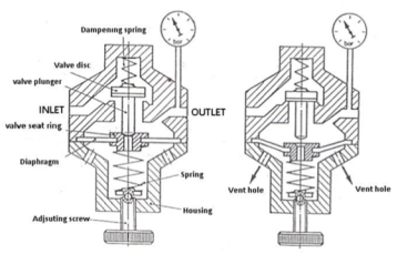
Fig. Venting type pressure regulator
- Outlet pressure is sensed by a diaphragm preloaded with an adjustable pressure setting spring.
- The compressed air, which flows through a controlled cross-section at the valve seat, acts on the other side of the diaphragm. The diaphragm has a large surface area exposed to secondary (outlet) pressure and is quite sensitive to its fluctuations.
- The movement of the diaphragm regulates the pressure.
- If the outlet pressure is low:whenever the more compressed air is consumed on the secondary side or load side, then load pressure reduces. Therefore less force acts on the diaphragm. The opposing higher spring force pushes the diaphragm in such a way as to move the valve disc more and permitting more air to flow to the secondary side and thus increasing the pressure again.
- If the outlet pressure is high:whenever the less compressed air is consumed on the secondary side or load side, then load pressure increases. Therefore more force acts on the diaphragm. The opposing higher spring force pulls down the diaphragm in such a way as to move the valve disc-less and permitting air to flow to vent hole and thus decreasing the pressure again
Non-Relieving or Non-Venting Type Pressure regulator
- In this case, compressed air cannot escape to the atmosphere in the event of high backpressure acting on the diaphragm
- As there is no exit path provided in the diaphragm for the trapped air.
The figure shows the non –relieving venting type pressure regulator.
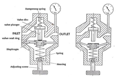
Fig. Non-venting type pressure regulator
5.4.3 Air Lubricator
The function of air lubricator is to add a controlled amount of oil with air to ensure proper lubrication of internal moving parts of pneumatic components. Lubricants are used to
- To reduce the wear of the moving parts
- Reduce the frictional losses
- Protect the equipment from corrosion
The lubricator adds the lubricating oil in the form of a fine mist to reduce the friction and wear of moving parts of pneumatic components such as valves, packing used in air actuators
Excessive lubrication is undesirable. Excessive lubrication may result in
- Malfunctioning of components,
- Seizing and sticking of components after prolonged downtime
- Environmental pollution
Schematic diagram of air lubricator is shown in Figure
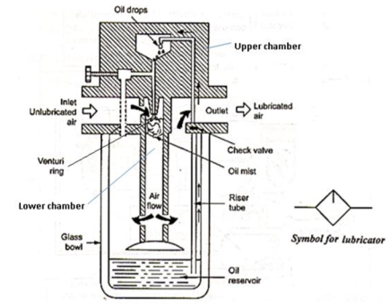
Fig. Air Lubricator
- As air enters the lubricator its velocity is increased by a venture ring.
- The pressure at the venture ring will be lower than the atmospheric pressure and the pressure on the oil is atmospheric.
- Due to this pressure difference between the upper chamber and the lower chamber, the oil will be drawn up in a riser tube. Oil droplets mix with the incoming air and form a fine mist.
- The needle valve is used to adjust the pressure differential between across the oil jet and hence the oil flow rate.
- The air-oil mixture is forced to swirl as it leaves the central cylinder so that large particles of oil are going back to the bowl and only the mist goes to outlet.
5.4.4 Filter Regulator Lubricator Unit (FRL Unit) /Service Unit
- In most pneumatic systems, the compressed air is first filtered and then regulated to the specific pressure and made to pass through a lubricator for lubricating the oil.
- Thus usually a filter, regulator, and lubricator are placed in the inlet line to each air circuit. They may be installed as separate units, but more often they are used in the form of a combined unit.
- Figure 1.6 shows the schematic arrangement of the installation of the Filter, Regulator, and Lubricator unit.
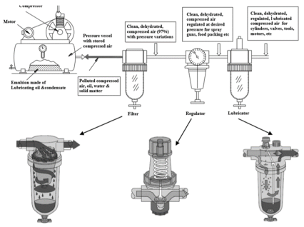
Fig. Installation of FRL unit
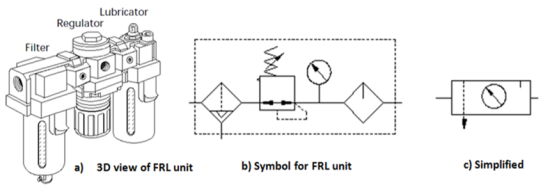
The combination of filter, regulator, and lubricator is called FRL unit or service unit.
Figure (a) gives a three-dimensional view of the FRL unit. Figure (b) gives a detailed symbol of the FRL unit. Figure (c) gives a simplified symbol of the FRL unit.
Pneumatic air silencers, also commonly called pneumatic mufflers, are a cost-effective and simple solution to reduce noise level and unwanted discharge of contaminants from pneumatics.
- A pneumatic silencer is used to vent pressurized air to the atmosphere. They are commonly installed on pneumatic 5/2-way solenoid valves, pneumatic cylinders, or fittings.
- Depending on the flow and pressure of the air coming out of the exhaust port, the pneumatic air exiting the device could produce noise that is potentially harmful to workers in the surrounding environment or cause noise issues in the application (theatre applications).
- In addition to noise, the exhaust air may emit contaminants during operation. Using a silencer exhaust cleaner can prevent harmful contaminants from entering the environment.
Figure shows examples of common pneumatic silencers.
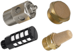
Fig. Examples of Mufflers
- Pneumatic silencers are designed in different shapes depending on the application. Application specifications that influence design are housing materials, working temperature ranges, working pressure range, and connection options.
- Additionally, silencers can be specified with a filter to prevent contaminants (i.e. oil) from being discharged into the atmosphere (see section silencer exhaust cleaner).

Fig. Symbol of muffler
The function of the dryer is to lower the dew point of the compressed air by removing the moisture from it. For simple applications, to remove excess humidity, we need a simple aftercooler, an air receiver, and a filter with condensate traps.
Types of Dryer
Generally, four basic types of air dryers are used in Industries.
- Absorption type dryer
- Adsorption type dryer
- Refrigeration dryer
5.6.1 Absorption type dryer
Schematic diagram of the absorption dryer is shown in Figure
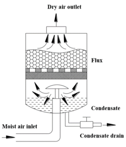
Fig. Absorption Dryer
- Absorption drying is a purely chemical process.
- The moisture in the compressed air forms a compound with drying agents like phosphoric pentaoxide in the tank.
- This causes the drying agent to break down.
- It is then discharged in the form of fluid at the base of the tank.
- Oil Vapour and oil particles are also separated in the absorption dryer. Large quantities of oil affect the efficiency of the dryer.
- Therefore it is advisable to include a fine filter in front of the dryer.
Advantages of Absorption dryer
- Simple to install
- Low mechanical wear because there are no moving parts
- No external energy requirement
Disadvantages of Absorption dryer
- 1 Maintenance cost is high
- 2. Low efficiency
- 3. Consumable cost is high
5.6.2 Adsorption type dryer
Adsorption is a physical process of moisture removal on the porous surface of certain granular materials.
The figure shows the various parts of the adsorption dryer.
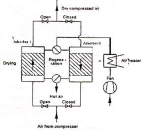
Fig. Adsorption Dryer
- Wet incoming compressed air after passing through a pre-filter is directed to the adsorption chamber containing the desiccant.
- Water vapor in the compressed air is absorbed by the desiccant. Thereafter dry air is allowed to pass to the application through the after the filter.
- Adsorption dryers usually have two desiccant filled chambers with interconnecting piping and switching valves.
- The valves permit removal of the collected moisture from one chamber while the other chamber is used to purify the compressed air.
- A contaminated desiccant bed can be regenerated by either elevating its temperature or by decreasing its pressure and purging.
5.6.3 Refrigerated Dryer
The layout of a typical refrigerated air dryer is shown in Figure
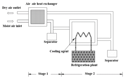
Fig. Refrigerated Dryer
- It is composed of a heat exchanger (stage1) and a refrigerating unit (Stage2) to reduce the temperature of the compressed air.
- The incoming warm and humid air is first passed through the air-to-air heat exchanger, and then through the refrigerating unit to reduce the temperature of the compressed to as low as +2.
- This drying method is based on the principle that if the compressed air is cooled to a temperature below the dew point, condensation talks place, and water is precipitated.
- Almost all the water and oil particles get condensed and collected in the water traps provided at appropriate points.
- The cooled compressed air is then filtered to remove from it the suspended solid particles and most of the oil mist.
The function of the directional control valve is to control the direction of flow in the pneumatic circuit. DCVs are used to start, stop, and regulate the direction of airflow and to help in the distribution of air in the required line.
5.7.1 Types of DCV
Directional valves control the way the air passes and are used principally for controlling commencement, termination, and direction of airflow. The different classification scheme of the pneumatic cylinders are given below
1. Based on construction
- Poppet or seat valves
- Ball seat valve
- Disc seat valve
- Diaphragm Valves
- Sliding spool valves
- Longitudinal slide valve - Suspended spool valves
- Rotary spool valves
2. Based on the number of ports
- Two-way valves
- Three-way valves
- Four-way valves
3. Based on methods of actuation
- Mechanical
- Electrical
- Pneumatic
4. Based on the Size of the port
Size refers to a valve’s port size. The port sizes are designated as M5, G1/8, and G1/4, etc. M refers to Metric thread, G refers to British standard pipe (BSP) thread.
5. Based on mounting styles
- Sub-base
- Manifold
- In-line
- Valve island
5.7.2 Poppet Direction Control Valves
There are three different types of poppet valves
A] Ball seat valve.
- In a poppet valve, discs, cones, or balls are used to control flow.
- The figure shows the construction of a simple 2/2 normally closed valve.
- If the push button is pressed, the ball will lift off from its seat and allows the air to flow from port P to port B.
- When the push button is released, spring force and air pressure keeps the ball back and closes airflow from port P to port B.
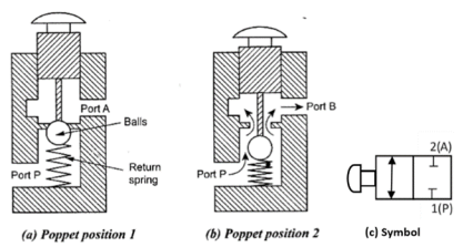
Fig. 2/2 Ball seat poppet valve
B] Disc seat poppet valve
- The figure shows the construction of a disc type 3/2 way DCV.
- When the push button is released, ports 1 and 3 are connected via a hollow push-button stem.
- If the push button is pressed, port 3 is first blocked by the moving valve stem and then the valve disc is pushed down so as to open the valve thus connecting port 1 and 3.
- When the push button is released, spring and air pressure from port 1 close the valve.
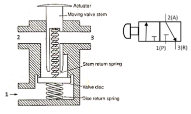
Fig. Disc seat poppet valve
C] Diaphragm valves
- The diaphragm between the actuator and valve body hermetically isolates the fluid from the actuator.
- The valves are maintenance-free and extremely robust and can be retrofitted with a comprehensive range of accessories, e.g. Electrical position feedback, stroke limitation, or manual override.
- The figure shows the unactuated and actuated position of diaphragm valves.
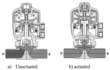
Fig. Diaphragm Valve
5.7.3 Spool Direction Control Valve
- Hand operated 3/2 DCV
- The cross-sectional views of 3/2 DCV (normally closed) based on spool design is shown below.
- When the valve is not actuated, port 2 and 3 are connected and port 1 is blocked.
Then the valve is actuated then port 2 and 1 are connected and port 3 is blocked.
- The figure shows a schematic diagram of the 3/2 spring-operated valve. There are three ports common port, normally open port and normally closed.
- When the valve is not actuated, there is flow from NO port to the common port.
- When the valve is actuated there is flow from NC to the common port.
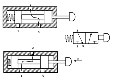
Fig. 3/2 Direction Control Valve (Normally Closed)
B. Pneumatically actuated 3/2 DCV
The cross-sectional views of pneumatically actuated NC type 3/2 DCV in normal position and actuated positions are shown in Figure
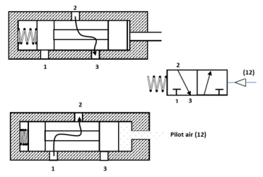
Fig. 3/2 DCV (Pneumatically Actuated)
- In the normal position, the working port (2) is closed to the pressure port (1) and open to the exhaust port (3).
- When the compressed air is applied through the pilot port (1-2), the spool is moved against the spring.
- In the actuated position, the working port (2) is open to the pressure port (1) and closed to the exhaust port (3).
- Thus, the application of the compressed air to the port 12 causes the pressure port (1) to be connected to the working port (2).
Pneumatically actuated valves have the following advantages
- Great flexibility for use in simple as well as a complex control system
- Adaptability for use in safety circuits.
- Various control functions can be easily incorporated as and when required.
- Feedback signals from sensors can be applied conveniently to control the pilot ports of these main valves. This means existing pneumatically actuated control circuits can be modified easily to incorporate any additional control requirement.
C. Pneumatically Actuated 4/2 DCV
- The valve shown in Figure is a 4/2 way valve pneumatically operated DCV. Switch over is effected by the direct application of pressure.
- If compressed air is applied to pilot spool through control port 12, it connects port 1 with 2 and 4 is exhausted through port 3.
- If the pilot pressure is applied to port 14, then 1 is connected with 4, and line 2 exhausted through port 3.
- On disconnecting the compressed air from the control line, the pilot spool remains in its current position until spool receives a signal from the other control side.
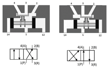
Fig. 4/2 DCV
D. Suspended Disc Direction Control Valves
- This valve is quite similar to the 4/2 way spool valve.
- The schematic diagram is shown in Figure.
- In this design,the disc is used instead of a spool. This suspended disc can be moved by pilot pressure or by a solenoid or by mechanical means.
- In this design, the main disc connects port 1 to either port 4 or 2. The secondary seat discs seal the exhaust port 3 whichever is not functional.
- These values are generally provided with manual override to manually move the cylinder.
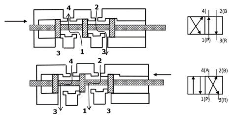
Fig. 4/2 DCV (suspended disc type)
- The figure below shows a 5/2 way valve which uses a suspended disk instead of the spool.
- In the spool type valve, spool controls the opening and closing of ports.
- In this type, suspended disc controls the opening and closing of ports.
- This suspended disc can be moved by pilot pressure at port 14 or port 12.
- When the pilot pressure acts through port 14. The ports 1 - 2 and 4 - 5 are connected and 3 is blocked.
- When the air is given to pilot line 12, then 2 - 3 and 4 -1 are connected and 5 is blocked.

Fig. 5/2 DCV (suspended disc type)
Advantages
- They have short actuation movement
- They are quick to operate because of small switching movement
- If signals are applied at both ports, the first signal will be dominant
Disadvantages
- Construction of the valve is complex
- Expensive
E. Rotary valves
- Therotaryspooldirectionalcontrolvalve (Figure)hasaroundcorewithoneormore passagesorrecessesinit.
- The core is mounted within a stationary sleeve. As the core is rotated within the stationary sleeve, the passages or recesses connect or block the ports in the sleeve.
- Theportsinthesleeveareconnectedtothe appropriatelinesofthefluidsystem.
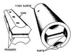
Fig. Parts of Rotary Spool DCV
The figure below shows three different positions of the core when the handle is rotated. The leftmost envelope of DCV connects P to B and A to T. Middle envelope of DCV blocks all ports. The rightmost envelope of DCV connects P to A and T to B.
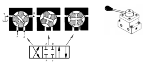
Fig. Different positions of 4/3 way rotary spool DCV
The table shows schematically the different positions of core and sleeve for various middle positions of 4/3 way Direction control valve.
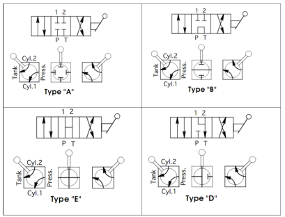
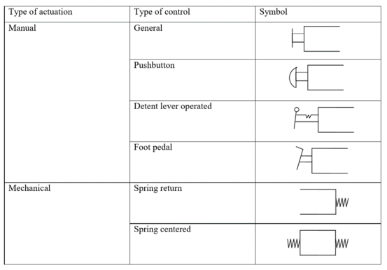
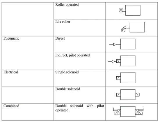
5.7.4 Method of Actuation
The methods of actuation of pneumatic directional control valves depend upon the requirements of the task.
Some basic methods of Actuations are given below
5.7.5 ISO DESIGNATION OF DIRECTION CONTROL VALVES
Valves are represented by symbols because actual construction is quite complex. A symbol specifies the function of the valve, method of actuation, no of ports, and ways.Pneumatic symbols have been standardized in ISO 1219-1:2006. (Fluid power systems and components – Graphic symbols and circuit diagram). Another standard ISO 1219-2:1995 establishes the rules for drawing diagrams of fluid power systems using symbols from ISO 1219-1. Port designations are described in ISO 5599.
Port markings: As per the ISO 5599, ports are designated using a number system. Earlier, a letter system was used to designate a port. The table below gives port markings.
Port | Old (Lettter) system | ISO (Number)System | Remarks |
Pressure port | P | 1 | Supply port |
Working port | A | 2 | 3/2 DCV |
Working ports | A, B | 4, 2 | 4/2 or 5/2 DCV |
Exhaust port | R | 3 | 3/2 DCV |
Exhaust ports | R, S | 5, 3 | %2 DCV |
Pilot ports | Z or Y | 12 | Pilot line (flow 1-2) |
Pilot ports | Z | 14 | Pilot line (flow 1-4) |
Pilot ports | Z or Y | 10 | Pilot line (no flow) |
Internal pilot ports | Pz, Py | 81, 91 | Auxiliary pilot line |
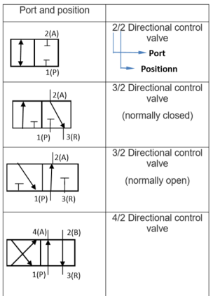
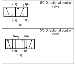
Ports and position: DCVs are described by the number of port connections or ways they control. For example Two way, three-way, four-way valves. Table 1 shows the Port markings of DCVs and the Table below shows commonly used DCVs with old and new designations.
Non-return valves permit the flow of air in one direction only, the other direction through the valve being at all times blocked to the airflow. Mostly the valves are designed so that the check is additionally loaded by the downstream air pressure, thus supporting the non-return action.
Among the various types of non-return valves available, those preferentially employed in pneumatic controls are as follows
- Check valve
- Shuttle valve
- Quick exhaust valve
- Two pressure valve
5.8.1Check Valve
- The simplest type of non-return valve is the check valve, which completely blocks airflow in one direction while permitting flow in the opposite direction with minimum pressure loss across the valve.
- As soon as the inlet pressure in the direction of free flow develops a force greater than that of the internal spring, the check is lifted clear of the valve seat.
- The check-in such valve may be plug, ball, plate, or diaphragm.
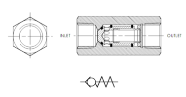
Fig. Check Valve
5.8.2 Shuttle Valve
- It is also known as a double control valve or double-check valve. A shuttle valve has two inlets and one outlet.
- At any one time, flow is shut off in the direction of whichever inlet is unloaded and is open from the loaded inlet to the outlet.
- A shuttle valve may be installed, for example, when a power unit (cylinder) or control unit (valve) is to be actuated from two points, which may be remote from one other.
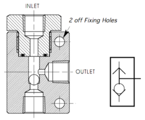
Fig. Shuttle valve
5.8.3 Quick Exhaust Valve
- A quick exhaust valve is a typical shuttle valve.
- The quick exhaust valve is used to exhaust the cylinder air quickly to the atmosphere. The schematic diagram of the quick exhaust valve is shown in Figure.
- In many applications especially with single-acting cylinders, it is a common practice to increase the piston speed during retraction of the cylinder to save the cycle time.
- The higher speed of the piston is possible by reducing the resistance to the flow of the exhausting air during the motion of the cylinder.
- The resistance can be reduced by expelling the exhausting air to the atmosphere quickly by using a Quick exhaust valve.
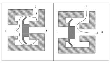
Fig. Quick Exhaust Valve
The construction and operation of a quick exhaust valve are shown in Figure.
- It consists of a movable disc (also called flexible ring) and three ports namely, Supply port 1, which is connected to the output of the final control element (Directional control valve).
- The Output Port, 2 of this valve is directly fitted on to the working port of the cylinder.
- The exhaust port, 3 is left open to the atmosphere
Forward Motion: During forward movement of the piston, compressed air is directly admitted behind the piston through ports 1 and 2 Port 3 is closed due to the supply pressure acting on the diaphragm. Port 3 is usually provided with a silencer to minimize the noise due to exhaust.
Return Motion: During the return movement of the piston, exhaust air from the cylinder is directly exhausted to the atmosphere through opening 3 (usually larger and fitted with silencer).Port 2 is sealed by the diaphragm. Thus exhaust air is not required to pass through long and narrow passages in the working line and final control valve
Typical applications of quick exhaust valve for single-acting and double-acting cylinders are shown in Figure.
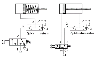
Fig. Application of Quick Exhaust Valve
5.8.4 Two Pressure Valve
- This valve is the pneumatic AND valve.
- It is also derivate of Non-Return Valve. A two-pressure valve requires two pressurized inputs to allow output from itself.
- The cross-sectional views of two pressure valves in two positions are given in Figure.
- As shown in the figure, this valve has two inputs 12 and 14 and one output 2.
- If the compressed air is applied to either 12 or input 14, the spool moves to block the flow, and no signal appears at output 2.
- If signals are applied to both the inputs 12 and 14, the compressed air flows through the valve, and the signal appears at output 2.

Fig. Two pressure valve
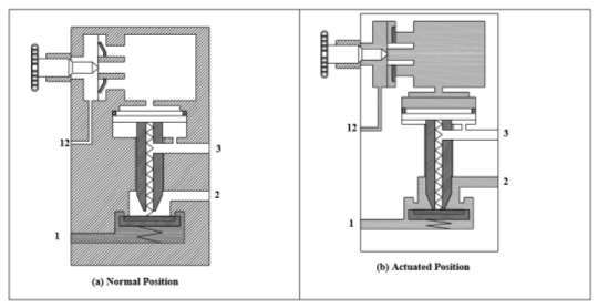
Fig. Time Delay Valve
- The time delay valve is a combination of a pneumatically actuated 3/2 direction control valve, an air reservoir, and a throttle relief valve. The time delay function is obtained by controlling the airflow rate to or from the reservoir by using the throttle valve.
- The pneumatic timer can be classified as
- On –delay timer
In on-delay timer, the 3/2 DCV is actuated after a delay with reference to the application of the pilot signal and is rest immediately on the application of the pilot signal.
2. Off – delay timer
In off delay timer, the 3/2 DCV is actuated immediately on the application of the pilot signal and is reset only after a delay with reference to the release of the pilot signal.
Pneumatic timers can also be classified according to the type of pneumatically actuated 3/2 DCv as:
1) Time delay valve, NC type
It can be seen that 3/2 DCV operates in the on delay mode permanently. But, in some designs, the valve can be operated in the off-delay mode by connecting the check valve in the reverse direction. For this purpose, the ports of the throttle check valve should be brought out.
2) Time delay valve, NO type.
The construction and function of an on-delay timer (NO) type are similar to that of an on-delay timer (NC) type except for the type of 3/2 DCV valve. In the on-delay valve (NO) type, a 3/2 DCV (NO) type is used whereas in the on-delay timer (NC) type, a 3/2 DCV (NC) type is used.
Timing diagrams for all four type of Pneumatic delay valve is given in Table
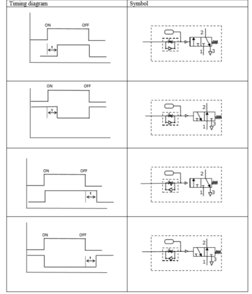
Fig. Timing Diagrams
Pneumatic actuators are the devices used for converting pressure energy of compressed air into mechanical energy to perform useful work.
Actuators are used to perform the task of exerting the required force at the end of the stroke or used to create displacement by the movement of the piston. The pressurized air from the compressor is supplied to the reservoir. The pressurized air from storage is supplied to the pneumatic actuator to do work.
Types of Pneumatic Actuators
Pneumatic cylinders can be used to get linear, rotary and oscillatory motion. There are three types of pneumatic actuator: they are
i) Linear Actuator orPneumatic cylinders
Ii) Rotary Actuator or Air motors
Iii) Limited angle Actuators
Pneumatic cylinders /Linear actuators
Pneumatic cylinders are devices for converting the air pressure into linear mechanical force and motion. The pneumatic cylinders are used for single-purpose applications such as clamping, stamping, transferring, branching, allocating, ejecting, metering, tilting, bending, turning, and many other applications.
The different classification scheme of the pneumatic cylinders are given below
5.10.1 Based on the application for which cylinders are used
- Light duty air cylinders
- Medium duty air cylinders
- Heavy-duty air cylinders
Components | Type of cylinder | ||
Light duty | Medium duty | Heavy duty | |
Cylinder tubes | Hard drawn Seamless aluminium or brass tubes Plastics | Hard drawn seamless brass tubes Aluminium, brass, iron or steel castings | Hard drawn seamless tubing, brass, bronze, iron or steel casting |
End covers | Aluminium alloy castings Fabricated aluminium brass, bronze | Aluminium brass, bronze, iron or steel castings, fabricated brass, bronze | High tensile castings |
Pistons | Aluminium alloy castings | Aluminium alloy castings, Brass, cast iron | Aluminium alloy castings, Brass, cast iron |
Piston rods | EN 8 or similar steel ground and polished or chrome plated | EN 8 steel, ground and polished or chrome plated, Ground and polished stainless steel | Ground and polished stainless steel |
Mounting brackets | Aluminium alloy casting | Aluminium, brass, iron castings | High tensile castings or fabricated |
5.10.2 Based on the cylinder action
- Single-acting cylinder
- Double-acting cylinder
- Single rod type double-acting cylinder
- Double rod type double-acting cylinder
A) Single-acting cylinders.
- A single-acting cylinder has one working port.
- The forward motion of the piston is obtained by supplying compressed air to the working port.
- The return motion of the piston is obtained by spring placed on the rod side of the cylinder.
- A single-acting cylinder is usually available in short stroke lengths [maximum length up to 80 mm] due to the natural length of the spring.
- Single-acting Cylinder exerts force only in one direction.
- Single-acting cylinders require only about half the air volume consumed by a double-acting cylinder for one operating cycle.
Schematic diagram of a single-acting cylinder is shown in Figure
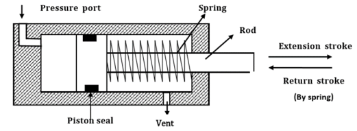
Fig. Single-acting Cylinder
There are varying designs of single-acting cylinders including:
i) Diaphragm cylinder
- In the diaphragm cylinder, the piston is replaced by a diaphragm of hard rubber, plastic, or metal clamped between the two halves of a metal casing expanded to form a wide, flat enclosure.
- The operating stem which takes place of the piston rod in the diaphragm cylinder can also be designed as a surface element to act directly as a clamping surface for example.
- Only short operating strokes can be executed by a diaphragm cylinder, up to a maximum of 50 mm. This makes the diaphragm type of cylinder particularly adaptable to clamping operations.
The schematic diagram of the diaphragm cylinder is shown in Figure.
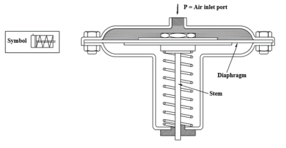
Fig. Diaphragm Cylinder
Ii) Rolling diaphragm cylinder
- They too contain a diaphragm instead of a the piston, which in this instance rolls out along the inner walls of the cylinder when air pressure is applied to the device, thereby causing the operating stem to move outwards.
- Compared with the standard diaphragm type, a rolling diaphragm cylinder is capable of executing appreciably longer operating strokes (averaging from 50 mm to 800mm).
- Separate guiding of the stem is not normally provided in these designs since the component being actuated by the cylinder usually cannot break out of set limits of motion.
- Any off-center displacement is compensated by the rolling diaphragm with no loss of power
Schematic diagram of Rolling diaphragm cylinder is shown in Figure
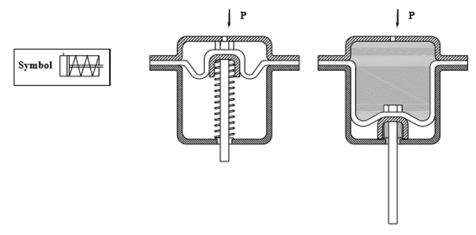
Fig. Rolling Diaphragm Cylinder
Iii) Gravity Return Single-acting Cylinder
The figure shows gravity return type single-acting cylinders
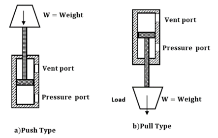
Fig. Gravity return Single-acting Cylinder
- In a push-type (a), the cylinder extends to lift a weight against the force of gravity by applying oil pressure at the blank end. The oil is passed through a blank end port or pressure port. The rod end port or vent port is open to the atmosphere so that air can flow freely in and out of the rod end of the cylinder. To retract the cylinder, the pressure is simply removed from the piston by connecting the pressure port to the tank. This allows the weight of the load to push the fluid out of the cylinder back to the tank.
- In pull-type gravity return type single-acting cylinder the cylinder (b) lifts the weight by retracting. The blank end port is the pressure port and the blind end port is now the vent port. This cylinder will automatically extend whenever the pressure port is connected to the tank.
Iv) Spring Return Single-acting Cylinder
Spring return single-acting cylinder is shown in Figure
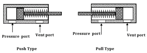
Fig. Spring return single-acting cylinder
- In part (a) push type the pressure is sent through pressure port situated at the blank end of the cylinder. When the pressure is released, the spring automatically returns the cylinder to the fully retracted position. The vent port is open to the atmosphere so that air can flow freely in and out of the rod end of the cylinder.
- Part (b) shows a spring return single-acting cylinder. In this design, cylinder retracts when the pressure port is connected to the pump flow and extend whenever the pressure port is connected to the tank. Here pressure port is situated at the rod end of the cylinder.
B) Double-acting cylinders.
- Double-actingcylinders are equipped with two working ports- one on the piston side and the other on the rod side.
- To achieve forward motion of the cylinder, compressed air is admitted on the piston side and the rod side is connected to exhaust.
- During return motion, supply air admitted at the rod side while the piston side volume is connected to the exhaust.
- Force is exerted by the piston both during forward and return motion of the cylinder.
- There is no return spring. In a double-acting cylinder, air pressure can be applied to either side (supply and exhaust) of the piston, thereby providing a pneumatic force in both directions.
- The double-acting cylinders are most commonly used in the application where larger stroke length is required.
Construction diagram of the double-acting cylinder is shown in Figure
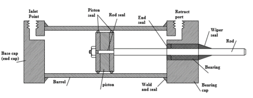
Fig. Construction of double-acting cylinder
There are two types of double-acting cylinders.
i) Double-acting cylinder with the piston rod on one side.
Ii) Double-acting cylinder with the piston rod on both sides
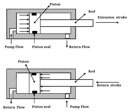
Fig. Double-acting Cylinder with the piston rod on one side
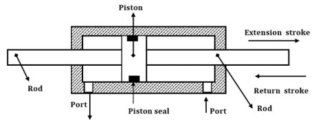
Fig. Double-acting Cylinder with the piston rod on both side
5.10.3 Based on the cylinder’s movement
- Rotating type air cylinder
- Non-rotating type air cylinder
5.10.4 Based on the cylinder’s design
- Telescopic cylinder
- Tandem cylinder
- Rodless cylinder
- Cable cylinder
- Sealing band Cylinder with the slotted cylinder barrel
- Cylinder with Magnetically Coupled Slide
- Impact cylinder
- Duplex cylinders
- Cylinders with sensors
A) Telescopic Cylinder
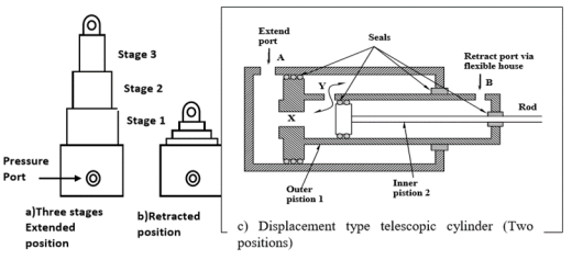
Fig. Telescopic Cylinder
- Extension stroke: When the pressure is applied at port A, airflow through port X and Y and pressure are applied on both sides of The piston 1. But the difference in areas causes the piston 1 to move to the right.Once the piston 1 fully extends, Inner The piston 2 will extend.
- Retraction stroke: To retract, the air is applied to port B. Air pressure will act on the annulus of the inner the piston 2 and moves inner the piston 2 to the left. When the inner the piston moves to left and started to close port X, air from port B goes to the annular side of the piston 1 via port Y and pushes the piston 1 to the left.
B) Tandem Cylinder
- Tandem cylinders are two separate double-acting air cylinders arranged in a line to one cylinder body so that the power generated by the two is added together, thereby approximately doubling the piston output.
- A tandem cylinder is used in applications where a large amount of force is required from a small-diameter cylinder.
- A tandem cylinder is simply two or more separate cylinders stacked end to end in a unit and with all the pistons mounted on a common the piston rod.
- The pressure is applied to both the pistons, resulting in increased force because of the larger area.
- Tandem cylinders are used where large output force is required with appreciable saving in bulk and weight.
- Tandem cylinders are employed where a small diameter of the assembly is required.
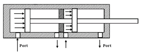
Fig. Tandem Cylinder
5.10.5 Graphical Symbol of Cylinders
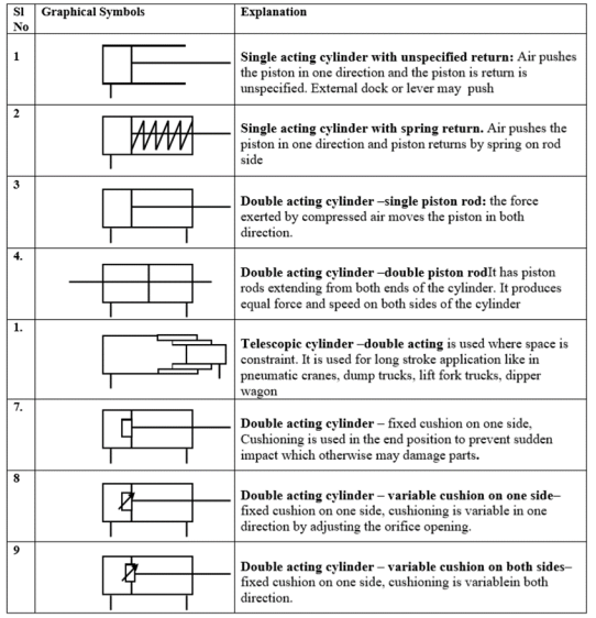
Speed regulation is achieved by use of flow control valve. Just like in hydraulic system, speed of cylinder can be regulated or controlled by using meter-in or meter-out circuit.
Meter-in Circuit
The figure shows a meter-in circuit with control of extending stroke.
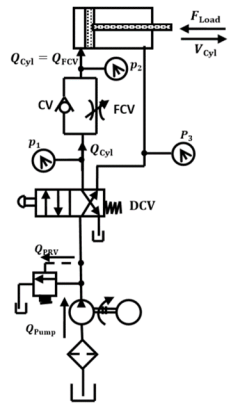
Fig. Meter-in Circuit
- The inlet flows into the cylinder is controlled using a flow-control valve.
- In the return stroke, however, the fluid can bypass the needle valve and flow through the check valve, and hence the return speed is not controlled.
- This implies that the extending speed of the cylinder is controlled whereas the retracing speed is not.
- Similarly, the meter-in circuit can also be used to control the return stroke by placing the flow control valve and check valve to the inlet port during the return stroke.
5.11.1 Meter-out Circuit
The figure shows a meter-out circuit for flow control during the extend stroke.
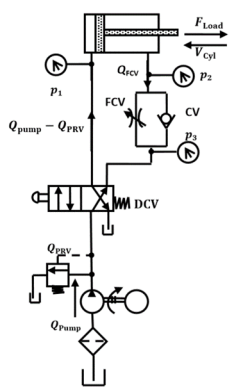
Fig. Meter-out Circuit
- When the cylinder extends, the flow coming from the pump into the cylinder is not controlled directly.
- However, the flow out of the cylinder is controlled using the flow-control valve (metering orifice).
- On the other hand, when the cylinder retracts, the flow passes through the check valve unopposed, bypassing the needle valve.
- Thus, only the speed during the extended stroke is controlled.
- Similarly, the meter-out circuit can also be used to control the return stroke by placing the flow control valve and check valve to the outlet port during the return stroke.
Both the meter-in and meter-out circuits mentioned above perform the same operation (control the speed of the extending stroke of the piston), even though the processes are exactly opposite to one another.
5.12 Basic Pneumatic Circuits
5.12.1 DIRECT CONTROL OF SINGLE-ACTING CYLINDER.
Pneumatic cylinders can be directly controlled by the actuation of the final directional control valve (Figure).
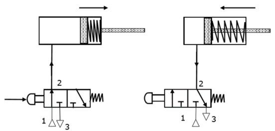
Fig. Direct Control of Single-acting Cylinder
- These valves can be controlled manually or electrically
- When the directional control valve is actuated by the push button, the valve switches over to the open position, communicating the working source to the cylinder volume. This results in the forward motion of the piston.
- When the push button is released, the reset spring of the valve restores the valve to the initial position [closed].
- The cylinder space is connected to exhaust port thereby the piston retracts either due to spring or supply pressure applied from the other port.
5.12.2 INDIRECT CONTROL OF SINGLE-ACTING CYLINDER
- This type of circuit is suitable for large single cylinders as well as cylinders operating at high speeds.
- The final pilot control valve is actuated by a normally closed 3/2 push-button operated valve.
- The final control valves handle a large quantity of air.
- When the push button is pressed, 3/2 normally closed valve generates a pilot signal 12 which controls the final valve thereby connecting the working medium to the piston side of the cylinder to advance the cylinder.
- When the push button is released, pilot air from the final valve is vented to the atmosphere through 3/2 NC – DCV.
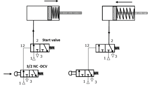
Fig. Indirect control of a single-acting cylinder
5.12.3 CONTROL OF SINGLE-ACTING CYLINDER USING “OR” VALVE
- The shuttle valve is also known as a double control valve or double-check valve.
- At any one time, flow is shut off in the direction of whichever inlet is unloaded and is open from the loaded inlet to the outlet. This valve is also called an OR valve.
- A shuttle valve may be installed for example, when the cylinder or valve is to be actuated from two points, which may be remote from one another.
- The single-acting cylinder in Figure can be operated by two different circuits.
- Examples include manual operation and relying on automatic circuit signals, that is, when either control valve 1 or control valve 2 is operated, the cylinder will work. Therefore, the circuit in Figure possesses the OR function.
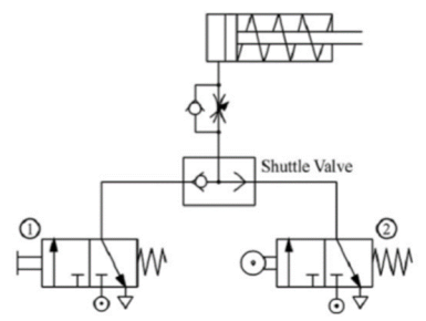
Fig. Control of a single-acting cylinder using OR valve
5.12.4 CONTROL OF SINGLE-ACTING CYLINDER USING “AND” VALVE
- Two Pressure valve is used as a AND valve in Pneumatics
- A two pressure valve requires two pressurized inputs to allow output from itself.
- Another name for an AND function is interlock control.
- This means control is possible only when two conditions are satisfied.
- A classic example is a pneumatic system that works only when its safety door is closed and its manual control valve is operated.
- The flow passage will open only when both control valves are operated.
- The figure shows the circuit diagram of an AND function circuit.
- The cylinder will work only when both valve 1 and 2 are operated.
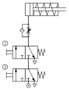
Fig. Control of a single-acting cylinder using AND valve
5.12.5 CONTROL OF SINGLE-ACTING CYLINDER USING “NOT” VALVE
- Another name for a NOT function is inverse control.
- To hold or lock an operating conveyor or a similar machine, the cylinder must be locked until a signal for canceling the lock is received.
- Therefore, the signal for canceling the lock should be operated by a normally open type control valve.
- However, to cancel the lock, the same signal must also cancel the locks on other devices, like the indication signal 3.
- The figure shows how the normally closed type control valve 1 can be used to cut off the normally open type control valve 2 and achieve the goal of changing the signal.
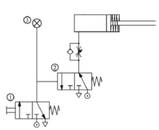
Fig. Control of a single-acting cylinder using NOT valve
5.12.6 DIRECT CONTROL OF DOUBLE-ACTING CYLINDER
- The only difference between a single-acting cylinder and a double-acting cylinder is that a double-acting cylinder uses a 5/2 directional control valve instead of a 3/2 directional control valve
- Usually, when a double-acting cylinder is not operated, outlet ‘B’ and inlet ‘P’ will be connected.
- In this circuit, whenever the operation button is pushed manually, the double-acting cylinder will move back and forth once.
- To control the speed in both directions, flow control valves are connected to the inlets on both sides of the cylinder.
- The direction of the flow control valve is opposite to that of the release of air by the flow control valve of the single-acting cylinder.
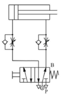
Fig. Direct control of a double-acting cylinder
5.12.7 INDIRECT CONTROL OF DOUBLE-ACTING CYLINDER USING MEMORY VALVE
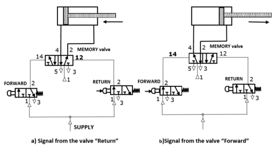
Fig. Indirect control of Double-acting cylinder using the memory valve
- When the 3/2 way valve meant for Forwarding motion (Figure b) is pressed, the 5/2 memory valve switches over through the signal applied to its pilot port 14.
- The piston travels out and remains in the forward end position. Double piloted valve is also called the Memory valve because now even if this push button meant Forward is released the final 5/2 control valve remains in the actuated status as both the pilot ports of 5/2 valves are exposed to the atmospheric pressure and the piston remains in the forward end position.
- When the 3/2 way valve meant for return motion (Figure a) is pressed, the 5/2 way valve switches back to the initial position through the signal applied to its pilot port 12.
- The piston then returns to its initial position and remains in the rear end position. Now even if the Return push button is released the status of the cylinder will not change.
- The circuit is called a memory circuit because it uses a 5/2 way double pilot memory valve. 5/2 way valve can remember the last signal applied in terms of the position of the spool in the absence of resetsprings, thus memorizing or storing the pneumatic signal. Double piloted 4/2 way valve also can be used as memory valve
5.12.8 Cascading Time Delay Circuit
Pneumatic timers are used to create time delay of signals in pilot operated circuits.Available as normally closed timers and normally open timers.Usually, pneumatic timers are on-delay timers.Delay of signals is very commonly experienced in applications such as bonding of two pieces.Normally open pneumatic timers are also used in signal elimination. Normally open pneumatic timers are used as a safety device in two hand blocks
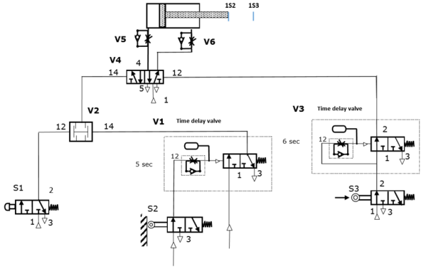
Fig. Cascading Time Delay Circuit
- If the push button S1 is actuated for a sufficiently long time period ( t = 5 seconds) then the air reservoir of time delay valve V1 is filled and corresponding 3/2 valve is switched, following which a signal is applied at input 1 of the dual pressure valve V2.
- If the push button S1 is actuated, the AND condition at the dual pressure valve is met. A signal is applied at the control port 12 of the control element V4. The valve V4 switches, the pressure is applied to the piston side of the cylinder 1A and the piston rod advances.
- After as short advancing distances, the limit switch S2 is released, the pressure is reduced in the air reservoir of the time delay valve V1 via the roller lever valve S2, and the integrated 3/2 way valve switches back to its initial position.
- The AND condition at the dual pressure valve is now no longer met. Actuation of the push button S1 becomes ineffective.
- Upon reaching the advancing position, the piston rod actuates the roller lever S3. The pressure line to the time delay valve V3 is now released and pressure in the air reservoir is increased. The rate of pressure increase is adjustable via the integrated flow control valve.
- When the switching pressure has been reached, the integrated 3/2 way valve switches, and a signal is applied at the control port 12 of the final control element V4. The valve V4 reverses and the piston rod retracts. Upon the release of the limit switch S3, the time delay valve V3 Switches to its initial position again.
- The limit switch S2 is actuated, when the piston rod reaches its initial position, the pressure in the air reservoir of the time delay V1 starts to increase until the switching pressure has been reached after t = 5 seconds.
- The integrated 3/2 way valve switches. The initial status of the system is now reached again and a new cycle can be started. The piston rod speed is set at the restrictors of the one-way flow control valves V5 and V6.
5.13 Electro-Pneumatic Control
- Electro pneumatics is now commonly used in many areas of Industrial low-cost automation. They are also used extensively in production, assembly, pharmaceutical, chemical, and packaging systems. There is a significant change in control systems. Relays have increasingly been replaced by programmable logic controllers to meet the growing demand for more flexible automation.
- Electro-pneumatic control consists of electrical control systems operating pneumatic power systems. In this solenoid valves are used as an interface between the electrical and pneumatic systems. Devices like limit switches and proximity sensors are used as feedback elements.
- Electro-Pneumatic control integrates pneumatic and electrical technologies, is more widely used for large applications. In Electro Pneumatics, the signal medium is the electrical signal either AC or DC source is used. The working medium is compressed air.Operating voltages from around 12 V to 220 Volts are often used. The final control valve is activated by solenoid actuation
- Control of the Electro-Pneumatic system is carried out either using a combination of Relays and Contactors or with the help ofProgrammable Logic Controllers [PLC]. A Relay is often is used to convert signal input from sensors and switches to the number of output signals [either normally closed or normally open].
- In Electro-pneumatic controls, mainly three important steps are involved:
- Signal input devices -Signal generation such as switches and contactor, Various types of contact and proximity sensors F
- Signal Processing – Use of the combination of Contactors of Relay or using Programmable Logic Controllers
- Signal Outputs – Outputs obtained after processing are used foractivation ofsolenoids, indicators or audible alarms
5.14 Application of Pneumatics in low-cost Automation
Industrial low-cost automation circuit makes the process simple and accurate in industries.
There are 2 types of circuit
5.14.1 Semi-Automatic Circuit
Fig shows a semi-automatic circuit used to control double-acting cylinder i.e. to control the operation carried out by the double-acting cylinder.
The various components used in this circuit are,
1) 3/2 DCV : Push button operated, spring return
2) 3/2 DCV : Roller actuated, spring return
3) 5/2 DCV : Pneumatic actuated, spring return
4) Consumer (C1) : Single acting cylinder, spring return
5) Consumer (C2) : Double acting cylinder
When the push button of DCV1 is pressed, the compressed air forces the piston of consumer 1 (C1) for forward stroke. At the end of stroke the roller get actuated which shifts DCV2 from spool-II to spool-I. Hence a signal is generated through DCV2 which forces the 5/2 DCV3 to change it's position from II to I. Hence the forward stroke of consumer 2 (C2) begins. As the push button of DCV1 is released, the reverse sequence takes place.
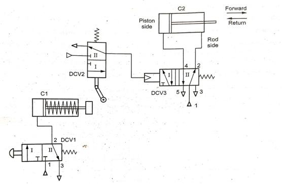
Fig. Semi-automatic circuit
5.14.2 Fully-Automatic Circuit
The following figure shows a fully automatic circuit that controls a single-acting cylinder through the motion of the double-acting cylinder.
The control of solenoid is achieved by using a feedback signal to the PIC interface board and software.
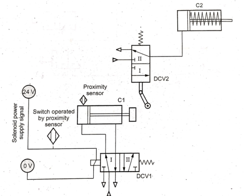
Fig. Fully-automatic circuit
The various components used in this circuit are,
1) 5/2 DCV : Solenoid actuated, spring return. 2) 3/2 DCV : Roller actuated, spring return.
3) Consumer (C1) : Double acting cylinder. 4) Consumer (C2) : Single acting cylinder.
When the consumer C1 completes it's return stroke, it actuates a proximity sensor. This sensor sends a signal to proximity switch, which sends electric signal to actuate 5/2 DCV and shift it from spool-II to spool-I. Hence consumer (C1) takes it's forward stroke and at the end of stroke actuate DCV2 from position-II to I.
Hence the compressed air gets a flow towards piston side of cylinder 2 (C2).
References:
1. Pipenger J.J, Industrial Hydraulics, McGraw Hill
2. Pinches, Industrial Fluid Power, Prentice Hall
3. Yeaple, Fluid Power Design Handbook
4. Andrew A. Parr, Hydraulics and Pneumatics, Elsevier Science and Technology Books
5. ISO - 1219, Fluid Systems and components, Graphic Symbols
6. Standard Manufacturer’s Catalogues