Unit 4
Ultra Sonic Testing Methods
It is a type of non-destructive technique in which an ultrasound transducer is connected to a diagnostic machine which is passed over the object being inspected. This transducer is typically separated from the test object by a couplant such as oil or by water as in immersion testing.
This technique is based on the principle that when the sound wave is propagated through the test piece the transmitted or reflected signal is monitored and interpreted depending upon that signal internal defects are identified in metals and non-metals.
The procedure of detection of defect:
- This process consists of several functional units such as the receiver transducer and display devices.
- A receiver is an electronic device that can produce high voltage electrical pulses driven by the receiver.
- The transducer generates high-frequency ultrasonic energy.
- The sound energy is introduced and propagates through the materials in the form of waves.
- When there is a discontinuity in the wave path, part of the energy will be reflected from the flawed surface.
- The reflected wave signal is transformed into an electrical signal by the transducer and is displayed on the screen.
- The reflected signal strength versus the time is displayed from a signal generated when an echo is received.
- Signal travel time can be directly related to the distance that the signal traveled.
- From the signal, information about the reflector location, size, orientation, and other features can sometimes be gained.
Key Take away points:
The technique is based on the principle that when the sound waves are propagated through a test piece, the transmitted signal is monitored and interrupted.
- The piezoelectricity means electricity from pressure and is derived from the Greek word piezo, which means to press or squeeze, and electric means electron which is the source of electric charge.
- Piezoelectricity is a result of the piezoelectric effect, which is a reversible process, in which material exhibiting the property of generation of electric charge from any mechanical strain, also exhibits the property of generation of the mechanical strain from any applied electrical field.
- It has found its application in the production and detection of sound waves, high voltage generations, electronic frequency generation, cigarette lighters, watches, sensors, actuators motors, reduction of vibration and noise, infertility treatment, etc.
Key takeaway points: The piezoelectricity means electricity from pressure and is derived from the Greek word which means press or squeezes electron which is the source of electric charge.
Ultrasonic probes or transducers are available in various varieties and it depends upon the application hence it is a very important factor to choose the appropriate transducer for a particular application.
Some important factors responsible for the selection of appropriate transducer are frequency desired, bandwidth, and focusing to optimize inspection capability.
Some of the transducers are mentioned below:-
- Electromagnetic Acoustic Transducer:
These transducers do not require any of the couplant as it generates the sound energy directly within the material placed in contact with this transducer.
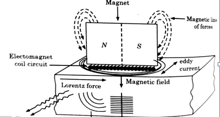
When a current-carrying or an electromagnet is used, with an ultrasonic frequency wave, an eddy current is induced in the material kept in proximity to the wire or electromagnet. These eddy currents will experience Lorentz force.
F=J×B

Fig.1: Electromagnetic transducer
2. Wheel transducer:
It operates similarly to delay line models.
They are typically used in applications where a large must be scanned and /or where the test piece material is sensitive to conventional ultrasonic couplants.
3. Delay line transducers:
It transmits and receives sound waves with one element coupled to the surface as with compression transducers.
The crystal is held off from the test piece surface by a delay block.
This permits inspection very close to the test piece surface.
4. Single and Twin Compression transducers:
In a single compression transducer, the straight beam is used to measure the thickness and to detect flaws on plates, bars, forgings, castings, and extrusions, during testing they are applied directly to the flat surfaces of the test materials.
In twin compression transducer, dual-element contact transducer’s measures thickness and detect flaws and corrosions in thin materials, especially where near-surface resolution is required.
5. Customer Transducer:
Customer transducers are often required for specialist applications. These often contain some elements for specific locations and angles. This probe is used to test railway track that incorporates both forward and backward facing twin element arrangement either side of conventional twin crystal arrangement.
Key Take away points:
The electronic transducer, single and twin compression transducer, customer transducer, wheel transducer, and delay line transducers, etc. are major types of ultrasonic probe.
It is one of the most scientific instruments ever developed. CRO provides accurate time and measurement of voltage signals over a wide range of frequencies.
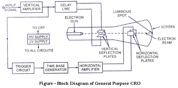
The heart of the CRO is a cathode ray tube along with the electron gun, fluorescent screen, and defecting system.
1.Working:
1. The signal to be displayed is amplified first by the vertical amplifier and then applied to the vertical deflection plate of CRT.
2. Some portion of the vertically amplified signal is applied to sweep trigger as a triggering signal.
3. This signal activates the sweep generator as a consequence of which, “sawtooth” waves are produced.
4. This sawtooth wave is applied to the horizontal amplifier and then applied to the horizontal deflection plate.

5. The maximum voltage Vm= is calculated by the given relationship.
Vm=Vrms/0.707
Vm=Maximum voltage and Vrms= Effective value of voltage or root mean square value (RMS) of the voltage.
2. Advantages
- It is well protected from damage if a signal is significantly stronger than expected.
3. Limitations:
- It is relatively fragile and expensive
- It is less accurate
4. Applications:
- It is used for comparing two different generated frequencies.
- It is used to determine the shift of phase in the circuit.
- It is used for studying the behaviour of beats.
- It is used for measuring repetitive signals.
Key Take away points:
The cathode ray oscilloscope is an instrument that we use in the laboratory for an inspection of the product.
1. Inspection of casting:
It consists of inspecting the surface of the casting with the naked eye or sometimes with a magnifying glass or microscope. It can only indicate surface defects such as blowholes, fusion, swells, external cracks, and mismatch. Almost all castings are subjected to a certain degree of visual inspection.
Dimensional inspection is carried out to make sure that the castings produced have the required overall dimensions including machining allowances. It may sometimes be necessary to break a part of the casting to take measurements of inside dimensions.
This is a rough test to indicate a flaw or discontinuity in a casting. The casting is suspended from suitable support free of all obstructions and tapped at various places on its surface with a small hammer. Any change in the tone produced indicates the existence of a flaw.
2. Forging:
The quality control through ultrasonic inspection of forgings of large dimensions for the energy industry still presents major limitations due to power losses occurring during the penetration of ultrasounds in the sample under examination.
The quality control through ultrasonic inspection of forgings of large dimensions for the energy industry still presents major limitations due to power losses occurring during the penetration of ultrasounds in the sample under examination.
Heavy rotor forgings for land-based power generation turbines and generators are inspected ultrasonically.
3. Extruded steel part and bars:
Ultrasonic non-destructive testing (NDT) is a well-established technique that utilizes high-frequency sound waves to locate cracks and other hidden flaws in metals, composites, and plastics.
In the metals industry, ultrasonic inspection is not only used to inspect finished parts but also to inspect raw material in the form of bars, billets, and plates supplied for further processing.
When employed appropriately by a qualified operator, ultrasonic NDT is quick and reliable, usually requires no test piece preparation other than wetting with ultrasonic couplant or water, and has no specific safety hazards or regulatory licensing requirements associated with its use.
1. Application in pipes:
- When it comes to pipe inspections, ultrasonic testing (UT) is the best tool available for non-destructive testing (NDT).
- Depending on the variation, UT can detect active or passive corrosion, among many other problematic corrosive anomalies.
2. Applications in rails:
- From the beginning of the development of railroads, it is always prone to various service failures.
- For reduction in catastrophic failures, the process of non-destructive testing came into the application.
- External defects on the rail can be detected by visual inspection.
- But in the case of internal, visual inspection fails to provide any information.
- Ultrasonic inspection use roller search units comprising a combination of different transducers at different angles to achieve the best inspection possible.
3. Dimensional measurement:
- Ultrasonic Testing (UT) uses high-frequency sound energy to conduct examinations and make measurements.
- Ultrasonic inspection can be used for flaw detection/evaluation, dimensional measurements, material characterization.
- It is sensitive to both surface and subsurface discontinuities.
- The depth of penetration for flaw detection or measurement is superior to other NDT methods.
- Only single-sided access is needed when the pulse-echo technique is used.
- It is highly accurate in determining the reflector position and estimating size and shape.
- Minimal part preparation is required.
- Electronic equipment provides instantaneous results.
- Detailed images can be produced with automated systems.
- It has other uses, such as thickness measurement, in addition to flaw detection.
It is an ultrasound-based method that follows a diagnostic imaging technique for examining the body structure using very high-frequency sound waves.
Generally, it has three steps:
- Producing a sound wave:
When strong, short electrical pulses are applied to a piezoelectric transducer, the frequencies between 2 to 20 MHz are generated.
This produces sound beams which are then focussed on the body and finally the beam focuses on the desired path. Besides a water-based gel is placed between the skin and probe for effective transmission of sound beams.
2. Receiving the echoes:
The reflected sound beams from the internal human body are received by the transducer, which vibrates the transducer and transforms the vibrations into electrical signals.
These signals travel to the oscilloscope or scanner when they are processed and displayed in a digital image.
3. Displaying the image:
The image displayed on the sonographic scanner can be further used for evaluation.
References:
- Dr. D Vijay Kumar, A textbook on Non- destructive testing.
- Google websites.
- Palash Awasthi, notes on NDT