Unit 5
Special NDT techniques
Working Principle and working of eddy current inspection:
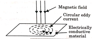
- When magnetic flux through a conductor changes, induced currents are set –up in closed paths on the surface of the conductor.
- These currents are in a direction perpendicular to the magnetic flux and are called eddy currents.
- When an alternating current is passed through a coil, a magnetic field is set up around it.
- The direction of the magnetic field changes with a change in the direction of the magnetic field during the cycles of alternating current.
- The induced eddy current produces its magnetic field in a direction opposite to the inducing primary magnetic field.
- The secondary magnetic field due to the eddy current interacts with the primary magnetic field and changes the overall magnetic field and the magnitude of the current following through the coil.
- This means that the impedance of the coil is altered due to the influence of the eddy current.
- During NDT, changes in impedance are displayed either on a meter or a CRT screen.

Fig.1: Eddy current
Method of ECT:
- Eddy current testing can detect very small cracks in or near the surface of the material, the surfaces need minimal preparation, and physically complex geometries can be investigated.
- It is also useful for making electrical conductivity and coating thickness measurements.
Methods of ECI are following as:
- The pulsed eddy current technique,
- Transmission method
- Reflection method
- The pulsed eddy current technique:
- This technique uses a step function voltage to excite the probe.
- The advantage of using a step function voltage is that it contains a continuum of frequencies.
- Since the depth of penetration is dependent on the frequency of excitation, information from a range of depths can be obtained all at once.
- As a result, the electromagnetic response to several different frequencies can be measured with just a single step.
- To prove the strength and ease of interpretation of the signal, a reference signal is usually collected, to which all other signals are compared.
- Flaws, conductivity, and dimensional changes produced a change in the signal and difference between the reference signal and the measurement signal that is displayed.
- This technique can be used for the detection and quantification of corrosion and cracking in multilayer aluminium aircraft structures.
2. Reflection methods:
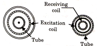
- In this method both the primary coil, which excites the electromagnetic field, and the secondary coil, which detects the discontinuity, are arranged adjacent to each other on either the outside or inside wall of the tube.

Fig.2: Reflection method
3. Transmission Method:
- When this method is employed, the exciting and receiving coils are placed at opposite walls either on the outside or inside diameter
- With this method, the receiving coil is affected only by those electromagnetic fields that have fast through the entire wall of the tube.
Equipment for ECT:
- Dedicated instruments:
- It includes crack detectors, thickness gauges, and conductivity meters.
- These instruments are designed to perform a specific operation only with much efficiency.
b. Standard impedance Plane Display Instruments:
It is a general-purpose instrument that can perform a variety of eddy current applications.
It displays the condition of the material in a characteristics manner and shows the variation in both inductive reactance and resistance during testing.
Working operation of impedance plane display instruments is controlled by the following factors.
- Frequency
- Sensitivity
- Dot position (horizontal/Vertical)
- Rotation
- Filters, and
- Gates
C. Multi-frequency Instruments:
- They work on multiple frequencies and eliminate the drawbacks of the other instruments.
- It can display the activity of the test at each frequency separately and can also show a mixed output of different signals.
- These instruments provide the following advantages:
- Suppression of undesirable variables.
- Optimization of frequency variables.
- Identification of signals by pattern
- Simultaneous operation of both absolute and differential mode.
Key Takeaway points: It is the technique that uses electromagnetic induction to detect defects in an electrically conductive material. In this technique, a conductive material carrying alternating current is bought in proximity to the test specimen, it generates eddy current.
Following are the techniques of the Eddy current testing:
- Single probe testing at a wide range of frequencies.
- Array scanning techniques.
- Multifrequency technique
- Pulsed eddy current technique
- Remote field technique.
- The sensitivity of defect detection depends upon the test material, its structure, the type of defect, the orientation of the defect, the depth of the defect, material quality, and surface condition that is surface roughness.
- The detection sensitivity also depends upon the particular test technique, the type, magnitude, and frequency of the excitation, and the type, size, and performance of the sensors.
- The encircling coils see a large surface area of the material under test and therefore, their sensitivity is intrinsically less than a point probe system.
- Besides, the lift-off effect is inescapable and the ‘fit’ of the coils around the rest object is critical.
- The greater the mismatch between the diameter of the coil and the diameter of and the diameter of the object, the lower will be sensitivity.
- Increasing the amplification of the measurement signal will be partially overcome this problem but such amplification applies also to noise levels and the sensitivity is usually limited by this factor.
Some of the advanced ECT methods are:
- Pulsed Eddy Current:
- Conventional ECT uses a sinusoidal alternating current of a particular frequency to excite the probe.
- Pulsed eddy current testing uses a step function voltage to excite the probe.
- The advantage of using a step function voltage is that such a voltage contains a range of frequencies.
- As a result, the electromagnetic response to several different frequencies can be measured with just a single step.
- Since the depth of penetration depends on the excitation frequency, information from a ranging depth can be obtained all at once.
- When comparing pulsed eddy current testing with the conventional ECT, it must be regarded as a continuous wave method where propagation takes place at a single frequency or, more precisely, over a very narrow frequency bandwidth.
- With the PEC method, the frequencies are excited over a wide band, the extent of which varies inversely with the pulse length; this allows multi-frequency operation.
- The total amount of energy dissipated within a given period is considerably less for pulsed-wave than for continuous wave of the same intensity, thus allowing higher input voltages to be applied to the exciting coil for PEC than conventional ECT.
- This way even high-temperature inspections are possible.
2. Eddy Current Array:
- Eddy Current Array (ECA) and conventional ECT share the same working principles.
- ECA technology provides the ability to electronically drive an array of coils arranged in a specific pattern called a topology that generates a sensitivity profile suited to the target defects.
- Data acquisition is achieved by multiplexing the coils in special patterns to avoid mutual inductance between the individual coils.
- The benefits of ECA are:
- Faster inspections.
- Wider coverage
- Less operator dependence- array probes yield more consistent results compared to manual raster scans.
- Better detection capabilities.
- Easier analysis because of simpler scan patterns.
- Improved positioning and sizing because of encoded data.
- Array probes can easily be designed to be flexible or shaped to specifications, making hard-to-reach areas easier to inspect.
- ECA technology provides a remarkably powerful tool and saves significant time during inspections.
- ECA inspection in carbon steel welds is regulated by ASTM standard E3052.
(a). Applications of ECT are:
- Testing of hot wire made of non-ferrous materials and ferrous materials above the Curie point.
- Testing of the cast, welded, forged, rolled and drawn products are possible.
- Detection of cracks of any discontinuity is possible.
- ECT can perform dimensional measurement of materials.
- Conductivity measurement can be done by using ECT.
- Conductive coating thickness measurement can be done.
- Inspection of railway components can be possible.
(b). Scope of ECT:
- Sensitivity to the surface and sub-surface defect
- Portability of test equipment
- It can measure conductivity accurately.
- It can detect through the surface coatings.
- It does not require contact between the probe and the test specimen.
(c). Limitations of ECT:
- It is very susceptible to magnetic permeability changes.
- It can be used for the inspection of conductive materials only.
- It has insensitive to defects parallel to the surface.
- It requires skilled personnel for performing the inspection.
- Distance between the probe and the test specimen is to be maintained.
(i) Types of probes:
- Based on modes of operation.
- Absolute probe:
- It consists of a single test coil placed on the test specimen, which is used to generate the eddy current, and a secondary coil called a balanced load, which balances the bridge circuit.
- When an alternating current is passed through the test coil, a magnetic flux is generated around the coil.
- When the coil is brought in proximity to a conductive material, eddy currents are generated, which appears as a resistance to the coil.
- This results in a change in impedance of the test coil and measuring this change one can use absolute coils for flaw detection, conductivity measurement, lift-off measurement, and thickness measurement
2. Differential probes:
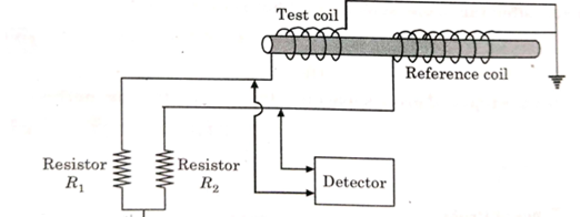
It consists of two active coils coupled to the test specimen with one portion of the test specimen being compared to another portion.

Fig.3: Differential probe
When a flawless test specimen is tested using this probe, no differential signal is developed between these two active coils.
However when one coil is over flawed part of a test specimen and the other one is over flawless part of the same test specimen, a differential signal is produced.
b. Based on the configuration of probes:
- Surface probes:
- They are designed to be handheld and consist of a coil of very fine wire encased in a protective housing used for scanning material surfaces.
- Most of the surface probes are either Bobbin wound type or horseshoe type.
- In the Bobbin wound probe, the coils are designed to wound up in such a way that the axis of the coil is perpendicular to the surface of the test specimen.
- This coil configuration is good for detecting surface defects oriented perpendicular to the surface of the test specimen that is they are insensitive to planar defects.
- For detecting planar defects, the horseshoe is a gap type probe s used, which consists of a pair of coils wounded on each end of the horseshoe so that flow of flux field is parallel to the surface of the test specimen.
- Surface probes are available in various configurations to meet a variety of applications like pencil probe, 900 probes, bolt hole probe, doughnut probe, pancake probe.
2. Shielded Probes:
- It is further classified as magnetically shielded probes and an eddy current shielded probe.
- In eddy current shield probes, coils are surrounded by a ring of highly conductive but non-magnetic material.
- In magnetically shielded probes, coils are encased within a non-conductive, ferromagnetic cylinder of ferrite.
3. Encircling Probes:
- These probes are similar to Bobbin probes except that the coil encircles the test specimen from outside and are used for testing of roads, wires, pipes, tubes, etc.
- As the test specimen is surrounded by coils from outside, an inspection of the entire circumference will be done with equal sensitivity.
(ii) Case study:
- Inspection of tube:
- We know that ECI is often used to detect corrosion, erosion, cracking, and other changes in the tubing.
- Heat exchangers and steam generators, which are used in power plants, have thousands of tubes that must be prevented from leaking.
- Eddy current techniques can be used to perform several dimensional measurements.
- Dimensions of cylindrical tubes and rods can be measured with either OD coils or internal axial coils, whichever is appropriate.
- Typical applications include measuring eccentricities of the diameter of tubes and rods and the thickness of tube walls.
- Long tubes are often tested by passing them at a constant speed through encircling coils and providing a close fit to achieve as high a fill-factor as possible.
- Tube more than 3 Inches Diameter:
- In the case of a tube having a diameter of more than 3 inches or 75 mm, it is generally no longer practical to inspect with an external encircling coil due to low resolution.
- For this inspection process, it is desirable to use multiple probes.
- It is composed of many electrically and mechanically separate probe coil assemblies.
- The number of probes to be used is used depending on the diameter of the tube to be inspected.
- In each assembly, probes are typically about 50 mm long and having 0.76 inches square cross-section with differential windings used.
- Probes are first electrically balanced individually and then wired in series. Thus, test signals are fed to separate detection and marking systems and we can get the desired result.
b. Tube up to 3 Inches Diameter:
- In this case, the inspection is performed by passing the tube longitudinally through a concentric coil assembly.
- The coil assembly consists of an energizing coil, a differential wound detector, and a magnetic saturating coil.
- The image of a three-dimensional object is recorded on a two-dimensional photographic plate. When a photograph is recorded, the phase distribution at the plane of the photograph is lost because emulsion on the photographic plate is sensitive only to intensity variations. Hence, three-dimensional characters are lost.
- A new method of recording optical images is known as holography.

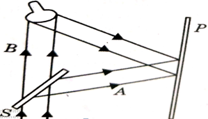
Fig. 4: Holography
- Holography means complete recording. In 1948, Dennis Galior gave an entirely new idea and proposed a method of recording not only the amplitude but also the phase of the wave.
- During the recording process, there is the superimposition of two waves, one emanating from the object and another coherent wave called the reference waves.
- The two waves produce interference fringes in the plane of the recording medium. The record is called a hologram.
- It memorizes an encoded image of the object and contains much more information than an ordinary photograph can record.
- Now the hologram is illuminated by the wave which is much similar to the reference wave known as a reconstructive wave. The principle of holography was laid down by Gabor and attained practical importance due to lasers in 1960.
Principle of Holography:
The basic principle of holography can be explained in two steps:
- Recording of the hologram:
Splitter s is used to divide a laser beam into two beams A and B.
The transmitted beam illuminates the object and the light scattered by the object impinges on a photographic plate. The reflected beam A falls on to the photographic plate. This beam is known as a reference beam.
An interference pattern that we get due to the superposition of two beams is recorded on the plate.
The developed plate is known as a hologram. The hologram contains enough information to produce a complete reconstruction of the object.
b. Reconstructing the image:
In the reconstruction process, the hologram is illuminated by a reconstruction wave, which in most cases is identical to the reference wave used for forming the hologram.
The reconstruction wave after passing through the hologram produces two images. One of them appears at the original position occupied by the object (virtual image) and the other (real image) can be photographed directly without using a lens.
The virtual image which is seen by looking through the hologram appears incomplete three-dimensional forms. If one moves his eyes, it is possible to see the other sides of the object.
The real image has all the properties as in the case of a virtual image and is the form between the observer and the plates as shown in the figure.
However, the real images reverse foreground and background, so the interest of the observer lies in the virtual image.
Key Takeaway points:
It is a new method of recording optical images is known as holography. It means a complete recording. During this process superimposition of two waves takes place.
- An infrared camera or monitor is used to observe the actual temperature or the variation over an area, of the surface of a plant item.
- Variations in heat transfers through the walls may be attributable to wall thinning or the build of a scale. It may indicate the presence of wet insulation and the potential conditions for corrosion under insulation (CUI).
- Alternatively, a heat source can be used to heat the surface and the dispersion of the heat observed.
- Unexpected changes in the heat flow can be used to identify defects.
- For containers containing hot or cold liquid, it is possible to observe the level of liquid in the item non-invasively.
- The size of the defect which can be detected will depend upon the optical parameters of the system and the resolution of the camera.
- In accessing the results, the emissivity of any pants or coatings on the component needs to be considered.
- Reflections of sunlight can also distort readings.
- The technique non-contacting and only line of sight to the surface under examination is required.
- It is quick and easy to apply but can only detect defects and or faults that cause a change in heat flow or the surface temperature of the item.
Key Takeaway points:
It is an example of infrared imaging science. Thermographic cameras usually detect radiation in the long infrared range of the electromagnetic spectrum.
- The phenomenon of generating transient elastic waves during the release of energy from localized sources within a solid material is called acoustic emission (AE). Dislocations resulting from plastic deformations cause AE.
- The elastic waves generated in this manner propagate in all directions and reach the surface of the material, where they are detected with the help of piezoelectric transducers.

Fig.5: Acoustic emission testing
- The piezoelectric transducer is directly attached to the test object with a coupling medium and secured with tape. The voltage output from the transducer is fed into the pre-amplifier, which is placed closed to the transducers.
- The pre-amplifier eliminates mechanical, acoustical, and background noise. However, it also generates electrical noise, which limits the sensitivity of the system.
- The pre-amplifier signal is passed through a variable bandpass filter to the main amplifier connected to a signal analysis system. The signal analysis system produces a signal each time the amplifier voltage signal exceeds a select threshold level.
The following parameters are used to identify AE events:
- Peak amplitude- the peak of the signal
- Arrival time- the time when the peak signal process the threshold signal.
- Duration time- the between the first threshold crossing and the peak amplitude.
- Ring count- the no. Of threshold crossing.
Applications:
- Vessel testing
- Structural integrity test
- Material testing
- Pipeline monitoring
- Leak detection
- Aircraft like assessment
- Rocket motor testing
Advantages:
- AE is a relatively rapid inspection tool for locating damage and is capable of providing an early warning of a sudden failure.
- It is a global monitoring tool and does not require access to the complete monitoring area.
Disadvantages:
- AE is produced only when the damage is active.
- In most cases, the method is only qualitative.
- AE signals are usually weak, which makes signal discrimination difficult.
- On other problems r are related to noise, reliability, and difficulty in the analysis of the source function and waveform. More research and development is needed in this area.
Key take away points:
The piezoelectric transducer is directly attached to the test object with a coupling medium and secured with tape. The voltage output from the transducer is fed into the pre-amplifier, which is placed closed to the transducers.
References:
- Dr. D Vijay Kumar, A textbook on Non- destructive testing.
- Google websites.
- Palash Awasthi, notes on NDT