Unit-2
Kinematics of fluid flow
The product of cross-sectional area of the pipe and the fluid speed at any point along the pipe is constant.
This product is equal to the volume flow per second or simply flows rate. Mathematically it is represented as Av = Constant
Continuity equation derivation Consider a fluid flowing through a pipe of non-uniform size.The particles in the fluid move along the same lines in a steady flow.
If we consider the flow for a short interval of time Δt,the fluid at the lower end of the pipe covers a distance Δx1 with a velocity v1, then: Distance covered by the fluid = Δx1 = v1Δt Let A1 be the area of cross section of the lower end then volume of the fluid that flows into the pipe at the lower end =V= A1 Δx1 = A1 v1 Δt
If ρ is the density of the fluid,then the mass of the fluid contained in the shaded region of lower end of the pipe is:
Δm1=Density × volume Δm1 = ρ1A1v1Δt ——– (1)
Now the mass flux defined as the mass of the fluid per unit time passing through any cross section at lower end is:
Δm1/Δt =ρ1A1v1 Mass flux at lower end = ρ1A1v1 ——————— (2)
If the fluid moves with velocity v2 through the upper end of pipe having cross sectional area A2 in time Δt,then the mass flux at the upper end is given by:
Δm2/Δt = ρ2A2v2 Mass flux at upper end =ρ2A2v2 ———————–(3)
Since the flow is steady,so the density of the fluid between the lower and upper end of the pipe does not change with time.Thus, the mass flux at the lower end must be equal to the mass flux at the upper end so:
ρ1A1v1 = ρ2A2v2 ———————-(4)
In more general form we can write:ρ A v =constant This relation describes the law of conservation of mass in fluid dynamics.If the fluid is in compressible, then density is constant for steady flow of in compressible fluid so ρ1 =ρ2
Now equation (4) can be written as: A1 v1 = A2 v2
In general: A v = constant
Key Takeaways:
This product is equal to the volume flow per second or simply flows rate. Mathematically it is represented as Av = Constant
2.2.1. Irrotational Flow:
Fluid elements moving in the flow field do not undergo any rotation,
ω= 0,  ×V=0
×V=0
The flow is irrotational if ω= 0 for every point.
The irrotational flow is always inviscid; i.e., Re>>1,but not turbulent and far from the boundaries where the viscous laminar layers are formed.

Subject too boundary conditions (usually no flow through a solid boundary) obtained when a body 9e.g an aerofoil) is placed in a flow which is uniform infinitely far upstream.
To satisfy boundary conditions, one often constructs a composite solution. Note that if  and
and  are solutions to Equation (1) then function (
 is also a solution since

In general then, if  where i=1,2,3,… are each solutions to Laplace equations, so must be

Where  , i=1,2,3,… are constants
This process of constructing a solution is known as Linear Superposition.
Function  are usually well know solutions to Laplace equations and are building-bricks of a composite solution. We construct a solution according to Eq. (2), finding necessary constants
  such that boundary conditions are satisfied.
We know identify some useful solutions to Laplace equations. Remember that for a potential function to be a solution to Laplace equation velocity must satisfy conditions of zero velocity and incompressibility (the mass-continuity equation).
If fluid is incompressible and because we are dealing with tw0-dimensional flows, then there must also exist a stream function. Below we will identify both the velocity potential ϕ(x,y) and the stream function ψ(x,y), for particular flows.
For irrotational, incompressible flow, we can say that stream function also satisfies equation i.e.,
Laplace equation for velocity potential 

Recall  and
and 
Hence (1) equivalent to

This means that stream function for sink/source flow also satisfies Laplace equation.
Hence the stream function could represent velocity potential.
Key takeaways:
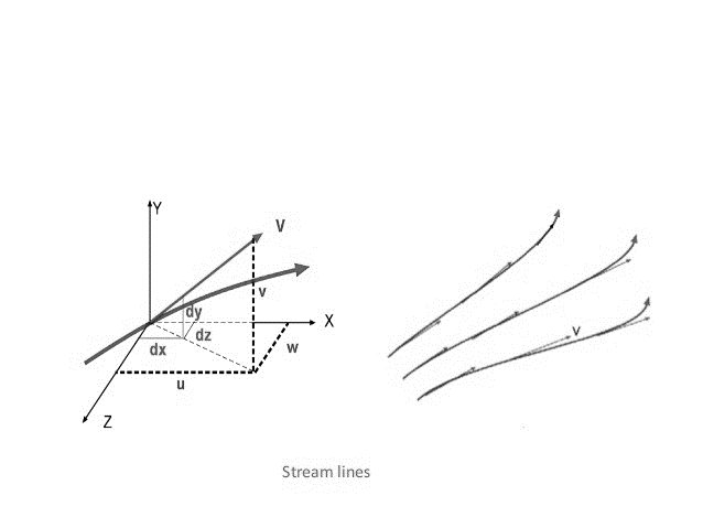
A streamline is a path traced out by a massless particle as it moves with the flow.
OR
A streamline is one that is drawn tangential to the velocity vector at every point in the flow at a given instant and forms a powerful tool in understanding flows.

Figure 1: Stream lines and streamline flow.
Explanation:
a) Streamlines cannot cross each other. If they were to cross, this would indicate two different velocities at the same point. This is not physically possible. The above point implies that any particles of fluid starting on one streamline will stay on that same streamline throughout the fluid
b) There cannot be any movement of the fluid mass across the streamlines.
c) Streamline sparing varies inversely as the velocity converging of streamlines at any particular direction shows accelerated flow in that direction.
d) Whereas path line indicates the path of one particular particle at successive instants of time, streamline indicates the direction of flow of a number of particles.
e) Series of streamlines represent the flow pattern at an instant. In steady flow, streamlines remain invariant with time. The path lines and streamlines will then be identical.
Stream tube: This is a fluid mass bounded by a group of stream lines or is an imaginary tube formed by a group of stream lines passing through a small closed curve which may or may not be circular. The contents of stream tube are known as current filament. E.g.: - pipes and nozzles
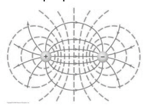
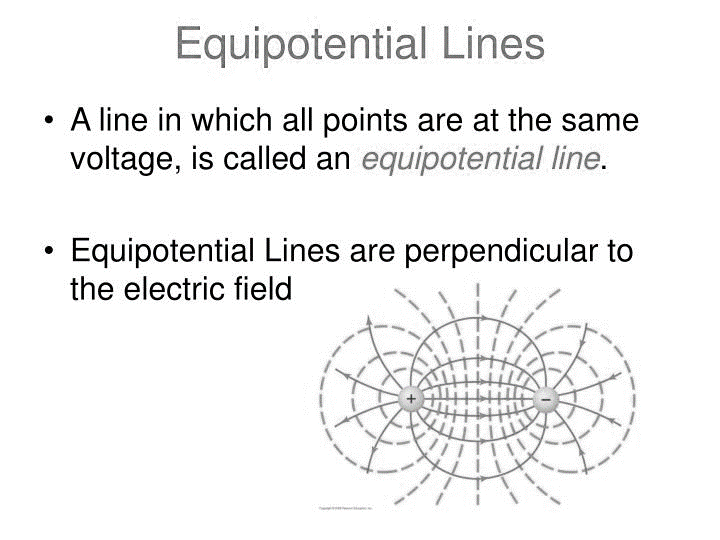
A line in which all line in which all points are at same voltage, is called equipotential line.
Equipotential lines are perpendicular to electric field.

Figure 2: Equipotential Lines
To represent this field graphically, lines of equal electric potential, called equipotential lines, are drawn around the source charge. Since these lines represent points in space with equal electric potential, there is no electric potential difference (ΔV=0) between any two points on the same equipotential line.
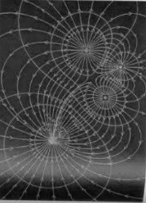
A surface in which all points are at the same voltage is called an equipotential surface.

Figure 3: Equipotential surface
Equipotential surface must be perpendicular to electric field.
A grid obtained by drawing a series of stream lines and equipotential lines is known as a flow net.

Figure 3: Flow net
Flow net provides a simple graphical technique for studying two – dimensional irrotational flows, when the mathematical calculation is difficult.
Key Takeaways:
References: