Unit – 3
Moment of Inertia
Assumption: The following assumptions are undertaken in order to derive a differential equation of elastic curve for the loaded beam
1. Stress is proportional to strain i.e. hooks law applies. Thus, the equation is valid only for beams that are not stressed beyond the elastic limit.
2. The curvature is always small.
3. Any deflection resulting from the shear deformation of the material or shear stresses is neglected.
It can be shown that the deflections due to shear deformations are usually small and hence can be ignored.
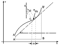
Fig.
Consider a beam AB which is initially straight and horizontal when unloaded. If under the action of loads the beam deflect to a position A’B’ under load or infact we say that the axis of the beam bends to a shape A’B’. It is customary to call A’B’ the curved axis of the beam as the elastic line or deflection curve.
In the case of a beam bent by transverse loads acting in a plane of symmetry, the bending moment M varies along the length of the beam and we represent the variation of bending moment in B.M diagram. Further, it is assumed that the simple bending theory equation holds good.

If we look at the elastic line or the deflection curve, this is obvious that the curvature at every point is different; hence the slope is different at different points.
To express the deflected shape of the beam in rectangular co-ordinates let us take two axes x and y, x-axis coincide with the original straight axis of the beam and the y - axis shows the deflection.
Further, let us consider an element ds of the deflected beam. At the ends of this element let us construct the normal which intersect at point O denoting the angle between these two normal.
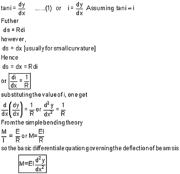
But for the deflected shape of the beam the slope is at any point C is defined,
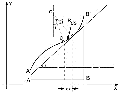
This is the differential equation of the elastic line for a beam subjected to bending in the plane of symmetry. Its solution y = f(x) defines the shape of the elastic line or the deflection curve as it is frequently called.
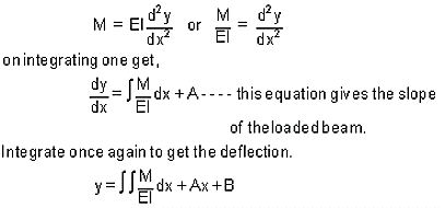
The governing differential equation is defined as
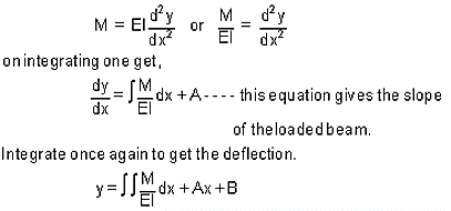
Where A and B are constants of integration to be evaluated from the known conditions of slope and deflections for the particular value of x.
Illustrative examples: let us consider few illustrative examples to have a familiarity with the direct integration method
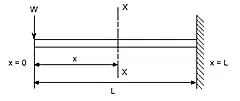
Case 1: Cantilever Beam with Concentrated Load at the end: - A cantilever beam is subjected to a concentrated load W at the free end, it is required to determine the deflection of the beam.
In order to solve this problem, consider any X-section X-X located at a distance x from the left end or the reference, and write down the expressions for the shear force and the bending moment
The constants A and B are required to be found out by utilizing the boundary conditions as defined below
i.e at x= L ; y= 0 ——————– (1)
at x = L ; dy/dx = 0 ——————– (2)
Utilizing the second condition, the value of constant A is obtained as
Case 2: A Cantilever with Uniformly distributed Loads:- In this case the cantilever beam is subjected to U.d.l with rate of intensity varying w / length. The same procedure can also be adopted in this case.
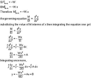

Boundary conditions relevant to the problem are as follows:
1. At x = L; y = 0
2. At x= L; dy/dx = 0
The second boundary conditions yields

Case 3: Simply Supported beam with uniformly distributed Loads:- In this case a simply supported beam is subjected to a uniformly distributed load whose rate of intensity varies as w / length.
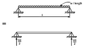
In order to write down the expression for bending moment consider any cross-section at distance of x metre from left end support.

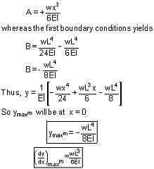
Boundary conditions which are relevant in this case are that the deflection at each support must be zero.
i.e. at x = 0; y = 0 : at x = l; y = 0
let us apply these two boundary conditions on equation (1) because the boundary conditions are on y, This yields B = 0.
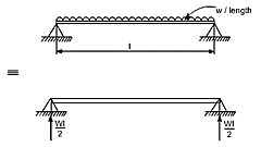
In this case the maximum deflection will occur at the center of the beam where x = L/2 [ i.e. at the position where the load is being applied]. So, if we substitute the value of x = L/2

Key takeaway points:
(i) The value of the slope at the position where the deflection is maximum would be zero.
(ii) The value of maximum deflection would be at the center i.e. at x = L/2.
The final equation which is governs

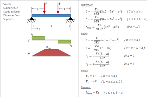
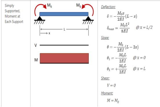
Deflection for Common Loadings:
1. Concentrated load at the free end of cantilever beam (origin at A):

Fig.
2. Concentrated load at any point on the span of cantilever beam

Fig.
- EIy=Px2(3a−x)/6 for 0 < x <a
- EIy=Pa2(3x−a)/6 for a < x <L
3. Uniformly distributed load over the entire length of cantilever beam
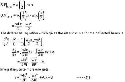
Fig.
4. Triangular load, full at the fixed end and zero at the free end

Fig.
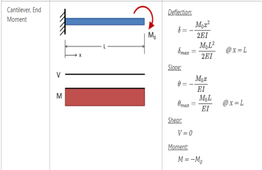
5. Moment load at the free end of cantilever beam

Fig.
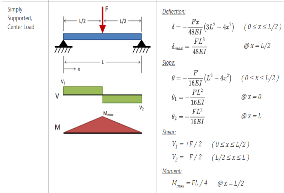
6. Concentrated load at the mid span of simple beam

Fig.
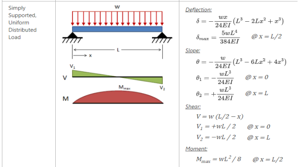
7. Uniformly distributed load over the entire span of simple beam

Fig 15
8 Triangle load with zero at one support and full at the other support of simple beam
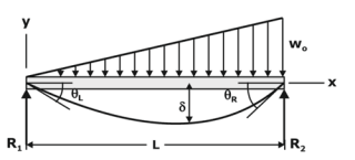
Fig 16
- θL= 7wL3/360EI
- θR= 8wL3/360EI
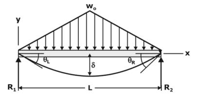
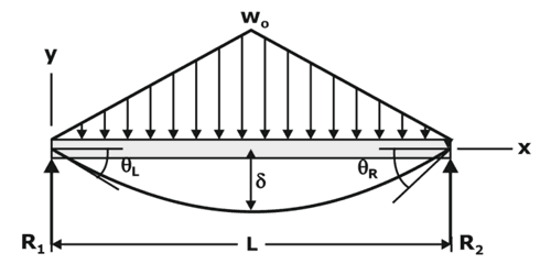
9. Triangular load with zero at each support and full at the midspan of simple beam




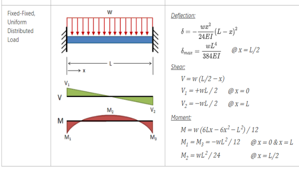
Fixed-Fixed Beams
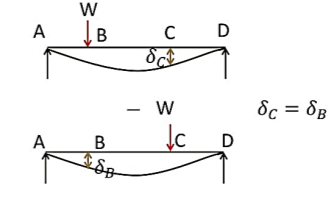
Betti’s theorem is also known as Maxwell – Betti reciprocal work theorems.
It says that the deflection at C due to a unit load at W at point B is the same as the deflection at B if same load W were applied at C.
.
Key takeaway point:
Reciprocal theorem: The reciprocal theorem states that the work done by forces acting through displacement of the second system is the same as the work done by the second system of forces acting through the displacements of the first system.
References