UNIT 5
Electronic Communication Systems

Fig. 1 Block diagram of elements of analog communication
Information Source
It produces a message that is analog in nature, i.e., the output of the information source is a continuous signal.
Analog carrier source
Sine wave is used as a carrier signal which will help in analog modulation.
Analog modulation
The carrier signal is superimposed with the message signal and then the modulated signal is obtained which is also analog in nature.
Communication channel
The analog modulated signal is transmitted via the communication channel towards the receiver end after addition of the requisite power levels.
Analog demodulation
At the receiver end, the incoming modulated signal is passed through an analog demodulation process which extracts the analog message signal. The analog message is then passed onto the final destination.
Destination
The nature of signal starting from the information source till the final destination is analog.
5.3 Transmission media: wired and wireless, need of modulation, AM and FM modulation schemes
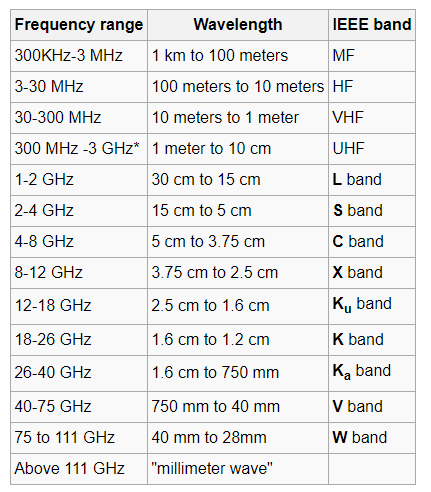
Receiver :-The received signal is processed by the various ckts like preamplifier, mixer, oscillator, detector, demodulator, driver ampr and power ampr.
In telephone baseband communication:- Analog information transmitted through parallel two wires.
The bandwidth of 300Hz to 3400Hz is adequate for a telephone voice conversation, 15Hz to 20Hz for music and 5Hz bandwidth for a typical video signal.
Transmission Media :-
1>. Guided:-Signals are transmitted via a physical and tangible guide betn the communicating points. These parallel wire, coaxial cable, wave guides and optical fibre.
2>. Unguided: - Physically there is no direct physical connection betn points such as microwave & satellite links. Mobile phone also uses unguided transmission media.
Necessity of Modulation :-
1>. Antenna height reduces
2>. Avoids mixing of signal
3>. Increases the range of communication [ InKilometers]
4>. Multiplexing of signals is possible
5>. Improves quality of reception of signal.
1>. Antenna height Reduces :- Antenna theory specifies that the height of the antenna required for radiation of radio waves is a function of wavelength of the freqn fed at the i/p of the antenna. Antenna height must be multiple of ( d/4 ),
Where ‘ d ‘ is the wavelength.
d = speed of light / freqn of signal
d = c / f = 3 x 10⁸ / f
eg : Consider the voice as analog baseband signal with f = 4 KHz
d = 3 x 10⁸ / 4 x 10³
d = 75 x 103 m
d = 75 km
Height of antenna required is d / 4
= 75 km / 4 = 18.75 km
Practically you cannot build the antenna of 18.7 km height. Consider this voice signal of 4 kHz freqn is used to modulate the carrier signal of 2 MHz freqn.
F = 2 MHz
D = c / f = 3 x 10⁸ / 2 x 106 = 150 m
Minimum height of antenna required = d / 4 = 150 / 4 = 37.5 m
Therefore antenna height required for radio communication reduces from 75 km to 37.5 meters due to modulation.
3>. Increase range of communication :- The freqn of baseband signal is low. At low freqn the signal radiation from antenna is poor or weak. Due to this reason the signal gets attenuated and cant travel long distance when it is transmitted.
Attenuation of the transmitted signal reduces when the freqn is increased.
Thus modulation increases the freqn of the signal to be radiated. Thus increase in freqn increases the range of communication.
Modulation Techniques :-
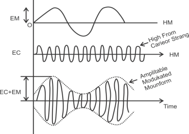
AM :-“ The process of changing the amplitude of the carrier wave as per the intensity [ amplitude ] of the modulating signal is called as Amplitude Modulation “.
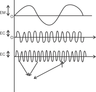
FM :- “ In freqn modulation the freqn of a carrier signal is varied by the modulating signal “.
“ The process of changing the freqn of the carrier wave according to the intensity [ amplitude ] of the modulating signal is called as freqn modulation “.
Comparison AM &FM :-
Sr No | A.M. | F.M. |
1>. | Amplitude of carrier is charged in accordance with amplitude of modulating signal. | Freqn of carrier is change in accordance with amplitude of modulating signal. |
2>. | Freqn is constant | Amplitude is constant |
3>. | The AM signal is given as, XAM (t) = Ac [ 1 + m x(t)] Cos (wct) | The FM signal is given as XFM (t) = Ac [ Cos (wct) + 2 ∏ Kf x(t)] |
4>. | Modulation index of AM, M = Am / Ac | Modulation index of FM, Βf = Δf / fm, where Δf = Am Kf
|
5>. | BW = 2 fm. Bandwidth of AM is 2W where W is bandwidth of modulating signal & 2fm is for single tone modulation. | Bandwidth of FM is BT = 2 ( βf + 1 )W, where W is bandwidth of modulating signal. For single tone modulation BW = 2 ( Kf Am + fm ) |
6>. | Requires small bandwidth compared to FM. | Required large BW compared to AM. |
7>. | It has only two sidebands for single tone modulation. | It has infinite sidebands even for single tone moduln. |
8>. | It is not suitable for high quality music broadcasting. | It is suitable for high quality music broadcasting. |
9>. | Noise immunity is low | It has better noise immunity than AM. |
10>. | It is suitable for long distance transmission | It is suitable for line of sight transmission. |
11>. | Used in MW, SW broadcasting, video transmission in T.V. | It is used in high quality music broadcasting audio broadcasting in T.V. |
12>. | Cannot reject interfering signals in the same band. | Can reject interfering signals in the same band due to capture effect. |
13>. | Transmission efficiency is poor due to use of Class A & amplifiers. | Transmission efficiency is better due to use of Class C ampr. |
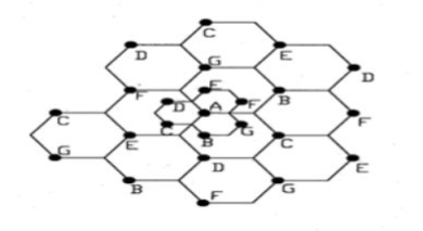
Cellular telephone systems, also referred to as Personal Communication Systems (PCS), are extremely popular and lucrative worldwide: these systems have sparked much of the optimism about the future of wireless networks. Cellular telephone systems are designed to provide two-way voice communication at vehicle speeds with regional or national coverage. Cellular systems were initially designed for mobile terminals inside vehicles with antennas mounted on the vehicle roof. Today these systems have evolved to support lightweight handheld mobile terminals operating inside and outside buildings at both pedestrian and vehicle speeds.
Frequency reuse
It is process of combining analog and digital signal to send over shared medium.
It divides the capacity of communication channel into multiple channels
Multiplexing is divided into space division, frequency division and time division multiplexing.
Space Division Multiplexing
In wired medium, separate point to point conductors are used to each channel.
In wireless medium multiple elements of antennas are used such that it forms phased array antenna.
Multiple output, multiple input and single input multiple output are the examples of this.
Frequency Division Multiplexing
In this multiple signal are send in distinct frequency in single medium.
The signals are electrical.
Radio, television broadcasting are the examples of FDM.
The service provides can send several channels or signals continuously to all subscribers even the customer has single cable connection.
Time Division Multiplexing
In this for separation of data streams the time is used instead of frequency and space.
It consists of group of bits in sequence one after another.
Each sequence is associated with each receiver.
Carriers sense multiple access and multidrug are the eaxples of time division multiplexing.
Channel Assignment
It means assigning channels or spectrum bands to radio interfaces for communication.
There are two channel assignment strategies in cellular system.
A. Fixed channel assignment:
B. Dynamic channel assignment:
Handoff strategies
Processing handoffs is an important task in any cellular radio system. Handoffs must be performed successfully and as infrequently as possible and be imperceptible to the user. In order to meet these requirements, system designer must specify an optimum signal at which to initiate a handoff.
This margin is given by cannot be too large or too small. If is large unnecessary handoffs which burden the MSC may occur and if is too small, there may be may be insufficient time to complete a handoff before a call is lost to meet these conflicting requirements. Figure is given which explains the different steps of handoff required to meet.
Following figure demonstrates the case where a handoff is not made and the signal drops below the minimum acceptable level to keep the channel active. This dropped call event can happen when there is an expansive delay by the MSC in assigning a handoff or when the threshold is set too small for the handoff time in the systems. Excessive delay may occur during high traffic conditions or due to no channels are available on any of the nearby base stations.

In deciding when to handoff, it is important to ensure that the drop in the measured signal is not due to momentary fading and the mobile is actually moving away from the serving base station. But when there is a drop in the measured signal level due to momentary fading and not due to the actual moving mobile away from the base station, that is situation if the handoff of a call takes place then such handoffs must be prevented by ensuring that the base station monitors the signal level for a certain period of time before the handoff is initiated.
Cell Splitting
Block diagram of GSM system
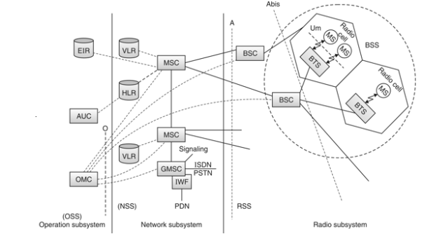
Fig. : GSM Architecture
A GSM system consists of three subsystems:
 1. Radio Sub System (RSS)
2. Network and Switching Subsystem (NSS)
3. Operation Sub System (OSS)
In GSM network all radio specific entities are comprised in radio sub systems. RSS consists the two main entities as:
 (i) Mobile Station (MS)
(ii) Base Station System
The basic function of RSS is to connect the mobile station to the network. The RSS can consist a number of Base Station Controller (BSC) and each BSC connects to the number of Base Transceiver Systems (BTS) and each BTS connects to a number of mobile stations (MS).
(i) Mobile Station (MS)
A Mobile Station (MS) consists of several functional groups.
(a) Mobile Terminal (MT)
Mobile Terminal offers common functions used by all services. MT transmits through the interface Um.
(b) TA (Terminal Adapter)
Terminal adaptation hides the radio specific characteristics.
(c) Terminal equipment (TE)
A user terminal through which the user receives and sends the data. It can be a headset, microphone etc.
(d) SIM (Subscriber Identity Module)
It is a card inserted into the MS. SIM uniquely identifies the user to the services, stores user parameters and enables the MS to connect to the GSM network.
(ii) Base Station Subsystem (BSS)
BSS have two main components :
(a) Base transceiver station
It connects to a number of mobile stations. The connection between the MS and BTS is established through the Um user interface. Main functions performed by BTS are as follows:
(i) Processing of signals
(ii) Formation of cells
(iii) Amplification of signals
(iv) Frequency hopping
(v) Channel coding and decoding
(vi) Encryption and decryption of data.

Fig.: MS and BTS connection through Um in GSM cell
(b) Base station controller
It manages a number of BTSS. It uses the Abis interface to connect to various BTSs main functions performed by BSC are as follows:
(i) Processing of signals
(ii) Switching between BTSs
(iii) Controlling BTSs
(iv) Reserving radio frequencies
(v) Frequency hopping and paging.
(vi) Authentication, encryption and decryption of data.
Network and Switching Subsystem (NSS)
The NSS consists of the following databases and switches:
(i) Mobile Services Switching Center (MSC)
(i) Establish the connections to other fined network, such as PSTN and ISDN via Gateway MSC (GMSC) or Interworking functions (IWF).
(ii) Handles all signaling needed for connection setup, connection release and handover of different connections to the other MSCs.
(iii) Call monitoring of MS.
(iv) Supplementary service support such as call forwarding multi-party calls.
(ii) Gateway Mobile Service Switching Centre (GMSC)
This is a MSC which handles connections to other networks like ISDN, PSTN, PSPDN.
(iii) Home Location Register (HLR)
(iv) Visitor Location Register (VLR)
Operation Sub System (OSS)
OSS work for the operation and maintenance of the entire network. The main components of OSS are Operation and Maintenance Centre (OMC), Authentication Centre (AuC) and Equipment Identity Register (EIR).
(i) Operation and Maintenance Center (OMC)
(ii) Authentication Centre (AuC)
(iii) Equipment Identity Register (EIR)
